 | –≠–ª–µ–∫—Ç—Ä–æ–Ω–Ω—ã–π –∫–æ–º–ø–æ–Ω–µ–Ω—Ç: ARZ225C05 | –°–∫–∞—á–∞—Ç—å:  PDF PDF  ZIP ZIP |
Document Outline
- ˛ˇ
- ˛ˇ
- ˛ˇ
- ˛ˇ
- ˛ˇ
- ˛ˇ
- ˛ˇ
- ˛ˇ
- ˛ˇ

39
RZ-COAXIAL
SWITCHES
TWO SERIES LINE-UP
OF IMPEDANCE 50
AND 75
FEATURES
1. Two series line-up of impedance 50
and 75
2. Mechanical switch with superb high-
frequency characteristics.
3. Low profile type package
TYPICAL
APPLICATIONS
1. Cellular phone base stations
(IMT-2000)
2. Digital broadcast equipment
3. Test measurement equipment
STANDARD PRODUCTS
CUSTOM PRODUCTS
RZ coaxial switches can be customized.
From the point of view of pricing and delivery we recommend our standard products, however, you may contact us if you require a circuit
configuration that differs from the products above. Please understand that, depending on the conditions, we may not be able to
customize in some cases.
Circuit arrangement
Impedance
Frequency
Connector
50
series
DPDT bypass
50
to 2.5 GHz
SMA
SP4T
75
series
SP4T with termination
75
to 1.5 GHz
BNC-J
Transfer
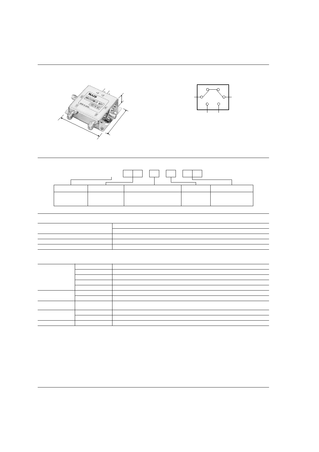
RZ
40
DPDT switch internal connection (bypass) type
(50
, to 2.5 GHz)
(mm
inch
)
45.0
1.772
56.0
2.205
14.9
.587
ORDERING INFORMATION
ARZ
Ex.
2
2
0
M
RZ coaxial switches
22: DPDT
0: Failsafe (50
)
M: Bypass
05: 5
12: 12
24: 24
Product name
Contact arrangement
Operating function and impedance
Added function
Operating voltage, V DC
PRODUCT TYPES
SPECIFICATIONS
1. Characteristics
Operating voltage (Vcc)
Part No.
Failsafe
5 V DC
ARZ220M05
12 V DC
ARZ220M12
24 V DC
ARZ220M24
High frequency
characteristics
(to 2.5 GHz,
Impedance 50
)
(Initial)
Impedance
50
Insertion loss
Max. 1.0 dB
Isolation
Min. 60 dB
V.S.W.R.
Max. 1.5
Input power
20 W
Electrical
characteristics
Operating voltage
Vcc±5%
Operate time
10 ms (excluding contact bounce time)
Expected life
(min. operations)
Electrical
5
◊
10
4
Ambient temperature
Operate
0∞C to +50∞C
32∞F to +122∞F
Storage
≠10∞C to +60∞C
+14∞F to +140∞F
Others
Connector
SMA

RZ
41
REFERENCE DATA
1. High frequncy characteristics
∑ Insertion loss
(Through and between terminal 1 to 3)
∑ Isolation
(Between terminal 1 to 3)
∑ V.S.W.R.
(Through and between terminal 1 to 3)
0.8
0.9
1.0
0
0.2
0.1
0.6
0.7
0.4
0.5
0.3
1GHz
3GHz
2GHz
Frequency
Insertion loss, dB
Through
Between terminal 1 to 3
80
90
100
0
20
10
30
60
50
70
40
1GHz
3GHz
2GHz
Frequency
Isolation, dB
1.1
1.0
1.5
1.2
1.4
1.3
1GHz
3GHz
2GHz
Frequency
V.S.W.R.
Through
Between terminal 1 to 3
DIMENSIONS
mm
inch
General tolerance: ±0.5
±.020
Equivalent circuit
Switching operation table
7
.276
44
1.732
50
1.969
56
2.205
5
.197
14.9
.587
4-2.75 dia.
4-.108 dia.
30
1.181
4
3
1
2
+2
+1
Control terminal +1
Control terminal +2
Control terminal ≠2
Control terminal ≠1
45
1.772
22
.866
RF terminal path (SMA)
Control terminal
3 to 4
(1, 2: no connection)
None
1 to 3
2 to 4
Control terminal +1, +2
Vcc
Control terminal ≠1, ≠2
Gnd
Control terminal +1
Control terminal ≠1
Control terminal +2
Control terminal ≠2
RF terminal 4
RF terminal 3
RF terminal 1
RF terminal 2

RZ
42
SP4T switch
(50
, to 2.5 GHz)
(mm
inch
)
76.2
3.000
68.9
2.713
15.0
.591
ORDERING INFORMATION
ARZ
Ex.
1
4
0
N
RZ coaxial switches
14: SP4T
0: Failsafe (50
)
N: None
05: 5
12: 12
24: 24
Product name
Contact arrangement
Operating function and impedance
Added function
Operating voltage, V DC
PRODUCT TYPES
SPECIFICATIONS
1. Characteristics
Operating voltage (Vcc)
Part No.
Failsafe
5 V DC
ARZ140N05
12 V DC
ARZ140N12
24 V DC
ARZ140N24
High frequency
characteristics
(to 2.5 GHz,
Impedance 50
)
(Initial)
Impedance
50
Insertion loss
Max. 0.6 dB
Isolation
Min. 60 dB
V.S.W.R.
Max. 1.5
Input power
20 W
Electrical
characteristics
Operating voltage
Vcc±5%
Operate time
10 ms (excluding contact bounce time)
Expected life
(min. operations)
Electrical
5
◊
10
4
Ambient temperature
Operate
0∞C to +50∞C
32∞F to +122∞F
Storage
≠10∞C to +60∞C
+14∞F to +140∞F
Others
Connector
SMA

RZ
43
REFERENCE DATA
1. High frequncy characteristics
∑ Insertion loss
(Between terminal C to 3)
∑ Isolation
(Between terminal C to 3)
∑ V.S.W.R.
(Between terminal C to 3)
0.8
0.9
1.0
0
0.2
0.1
0.6
0.7
0.4
0.5
0.3
1GHz
3GHz
2GHz
Frequency
Insertion loss, dB
80
90
100
0
20
10
30
60
50
70
40
1GHz
3GHz
2GHz
Frequency
Isolation, dB
1.1
1.0
1.5
1.2
1.4
1.3
1GHz
3GHz
2GHz
Frequency
V.S.W.R.
DIMENSIONS
mm
inch
General tolerance: ±0.5
±.020
Equivalent circuit
Switching operation table
Note) Do not apply multiple control signals simultaneously.
1
2
C
3
4
3
C
2
1
4
44.8
1.764
22.4
.882
2.54
.100
68.9
2.713
62.9
2.476
56.9
2.240
4-2.75 dia.
4-.108 dia.
2.54
.100
2.54
.100
15
.591
2.54
.100
2.54
.100
12.85
.506
Control terminal 4
NC
Control terminal 2
NC
NC
NC
NC
Control terminal 1
Control terminal 3
Control terminal Vcc
15.0
±
0.2
.591
±
.008
7.45
.293
5.2
.205
6
.236
10.60
.417
76.2
3.000
38.1
1.500
RF terminal path (SMA)
Control terminal
C to 1
NC
C to 2
Control terminal Vcc
Vcc±5%,
control terminal 2
Gnd
C to 3
Control terminal Vcc
Vcc±5%,
control terminal 3
Gnd
C to 4
Control terminal Vcc
Vcc±5%,
control terminal 4
Gnd
Control terminal 1
NC
RY3
RY3
RY2
RY1
RY2
RY1
Control terminal 2
Control terminal 3
Control terminal 4
RF terminal 4
RF terminal 3
RF terminal 2
RF terminal 1
RF terminal C
Control terminal Vcc