
383
CA-RELAYS
AUTOMOTIVE POWER
RELAYS -- SMALL SIZE,
LIGHT WEIGHT AND
COMPLETELY WATER TIGHT
FEATURES
1. Small size and light weight
For space saving, the outside dimensions
of the main body are reduced to be 21.5
mm (length)
◊
14.4 mm (width)
◊
37 mm
(height)
(.846
◊
.567
◊
1.457 inch)
. and
the weight is also reduced to be approx.
19 g
.67 oz
(Direct coupling 1 Form A,
1 Form B type)
2. Water tightness
Since the relays comply with the water
tightness standards, JIS D 0203, water
and dust will not enter the relay even if it is
mounted in the engine area.
3. Low operaing power (1.4W) type is
available (1 Form A, 1 Form B)
4. Since the terminal arrangement
complies with JIS D5011 B4-M1, com-
mercial connectors are available for
these types of relays.
SPECIFICATIONS
Contact
Type
12 V DC
24 V DC
Arrangement
1 Form A
1 Form B
1 Form C
1 Form C
Initial contact resistance, max.
(By voltage drop 6 V DC 1A)
50 m ohm
Contact material
silver alloy
Contact voltage drop, max.
0.3 V
After electrical life test,
by voltage drop
12 V DC 20 A
(1.4 W type),
12 V DC 30 A
(1.8 W type)
0.3 V
After electrical life test,
by voltage drop
12 V DC 20 A
0.4 V
After electrical life test,
by voltage drop
12 V DC 20 A
0.4 V
After electrical life test,
by voltage drop
24 V DC 10 A
Rating
Nominal switching capacity
(resistive load)
20 A 12 V DC
(1.4 W type)
30 A 12 V DC
(1.8 W type)
20 A 12 V DC
10 A 24 V DC
(ON: 2s, OFF: 2s)
Max. switching voltage
16 V
15 V
30 V
Max. switching current
120 A (1.4 W type)
150 A (1.8 W type)
120 A
100 A
50 A (Inrush current)
Max. carrying current
20 A continuous
(1.4 W type)
30 A for 1 min
(1.8 W type)
20 A continuous
20 A continuous
10 A continuous
Nominal operating power
1.4 W / 1.8 W
1.8 W
Expected
life (min.
operations)
Mechanical (at 120 cpm)
10
6
5
◊
10
5
Electrical
20 A
(1.4 W, 1.8 W type)
10
5
(ON: 2s, OFF: 2s)
10
5
(ON 2s, OFF 2s)
10
5
30 A
(1.8 W type)
2
◊
10
4
(ON: 3s, OFF: 15s)

CA
384
Characteristics (at 20
∞
C
68
∞
F
)
Electrical life (min. operation)
Remarks
* Specifications will vary with foreign standards certification ratings.
*
1
Detection current: 10 mA
*
2
Excluding contact bounce time
*
3
Half-wave pulse of sine wave: 11ms; detection time: 10
µ
s
*
4
Half-wave pulse of sine wave: 6ms
*
5
Detection time: 10
µ
s
*
6
Refer to 5. Conditions for operation, transport and storage mentioned in
AMBIENT ENVIRONMENT (Page 61)
Type
12 V DC
24 V DC
Max. operating speed
15 cpm 1.4 W type: at nominal load
1.8 W type: at 20 A
15 cpm (at nominal load)
Initial insulation resistance
Min. 10
at 500 V DC
Initial breakdown
voltage*
1
Between open contacts
500 V rms for 1 min.
Between contacts and coil
500 V rms for 1 min.
Operate time*
2
(at nominal voltage)
Max. 10 ms at 20
∞
C
Max. 10 ms
Release time (without diode)*
2
(at nominal voltage)
Max. 10 ms at 20
∞
C
Max. 10 ms
Shock resistance
Functional
Min. 200 m/s
2
{20 G}
Min. 100 m/s
2
{10 G}
Min. 100 m/s
2
{10 G}*
3
Destructive*
4
Min. 1,000 m/s
2
{100 G}
Vibration resistance
Functional*
5
Rubber bracket A type: Min. 100 m/s
2
{10 G}, 50 to 500Hz
Direct coupling type or Screw-mounting type: Min. 44.1 m/s
2
{4.5 G}, 10 to 100 Hz
Min. 44.1 m/s
2
{4.5 G},
10 to 100Hz
Destructive
Rubber bracket A type: Min. 100m/s
2
{10 G},50 to 500Hz
Direct coupling type or Screw-mounting type: Min. 44.1 m/s
2
{4.5 G}, 10 to 100 Hz
Min. 44.1 m/s
2
{4.5 G},
10 to 500Hz
Conditions for operation,
transport and storage*
6
(Not freezing and condensing
low temperature)
Ambient
temp.
≠30
∞
C to +80
∞
C
≠22
∞
F to +176
∞
F
Humidity
5 to 85% R.H.
Water-proof standard
Plastic sealed type: JIS DO203S2, Dust cover type: JIS DO203R2
JIS DO203S2
Unit weight
Rubber bracket A type : 23 g .
81 oz
Direct coupling type or Screw-mounting type:
19 g .
67 oz
31 g
1.09 oz
Nominal coil voltage, V DC
Motor load
(operating frequency ON: 2 s, OFF: 2 s)
Halogen lamp load
(operating frequency ON: 1 s, OFF: 14 s)
1 Form A, 1 Form B
12
10
5
, 20 A 12 V DC
10
5
, 20 A 12 V DC
1 Form C
12
10
5
, 20 A 12 V DC
10
5
, 20 A 12 V DC
24
10
5
, 10 A 24 V DC
10
5
, 6 A 24 V DC
ORDERING INFORMATION
CA
1a
F
S
12 V
A
5
Contact
arrangement
Notes: 1. Type with resistor/diode inside are available as options. Please consulf our sales office.
2. Standard packing: Carton: 20 pcs. Case: 200 pcs.
Mounting method
Classification by type
1a: 1 Form A
1b: 1 Form B
1 : 1 Form C
Protective construction
Nil: Plastic sealed type
F: Dust cover type
Coil voltage
(DC)
12 V
24 V (1 Form C only)
Nil: 1 Form C
5: 1 Form A or
1 Form B
Nominal operating power
Nil: Standard type (1.8 W)
S: Low operating power type (1.4 W)
(1 Form A, 1 Form B)
A: Rubber bracket A type
A:
(1 Form A, 1 Form B)
N: Screw mounting type
C: Direct coupling type
COIL DATA
1) Standard type
Contact
arrangement
Mounting type
Plastic sealed
type
Dust cover type
Nominal
voltage,
V DC
Pick-up voltage,
V DC (max.)
(at 20
∞
C
68
∞
F
)
Drop-out
voltage, V DC
(min.)
(at 20
∞
C
68
∞
F
)
Nominal oper-
ating current,
mA (
±
10%)
(at 20
∞
C
68
∞
F
)
Coil resistance,
(
±
10%)
(at 20
∞
C
68
∞
F
)
Nominal
operating
power, mW
(at 20
∞
C
68
∞
F
)
Usable
voltage
range, V
DC
1 Form A
Rabber bracket A CA1a-12V-A-5
CA1aF-12V-A-5
12
8
0.6 to 6
150
80
1.8
10 to 16
Screw-mounting
CA1a-12V-N-5
CA1aF-12V-N-5
12
8
0.6 to 6
150
80
1.8
10 to 16
Direct coupling
CA1a-12V-C-5
CA1aF-12V-C-5
12
8
0.6 to 6
150
80
1.8
10 to 16
1 Form B
Rabber bracket A CA1b-12V-A-5
CA1bF-12V-A-5
12
8
0.6 to 6
150
80
1.8
10 to 16
Screw-mounting
CA1b-12V-N-5
CA1bF-12V-N-5
12
8
0.6 to 6
150
80
1.8
10 to 16
Direct coupling
CA1b-12V-C-5
CA1bF-12V-C-5
12
8
0.6 to 6
150
80
1.8
10 to 16
1 Form C
Screw-mounting
CA1-DC12V-N
≠
12
8
0.6
150
80
1.8
10 to 15
Direct coupling
CA1-DC12V-C
≠
12
8
0.6
150
80
1.8
10 to 15
Screw-mounting
CA1-DC24V-N
≠
24
16
1.2
75
320
1.8
20 to 30
Direct coupling
CA1-DC24V-C
≠
24
16
1.2
75
320
1.8
20 to 30
(
)
CA
385
2) Low operating power type
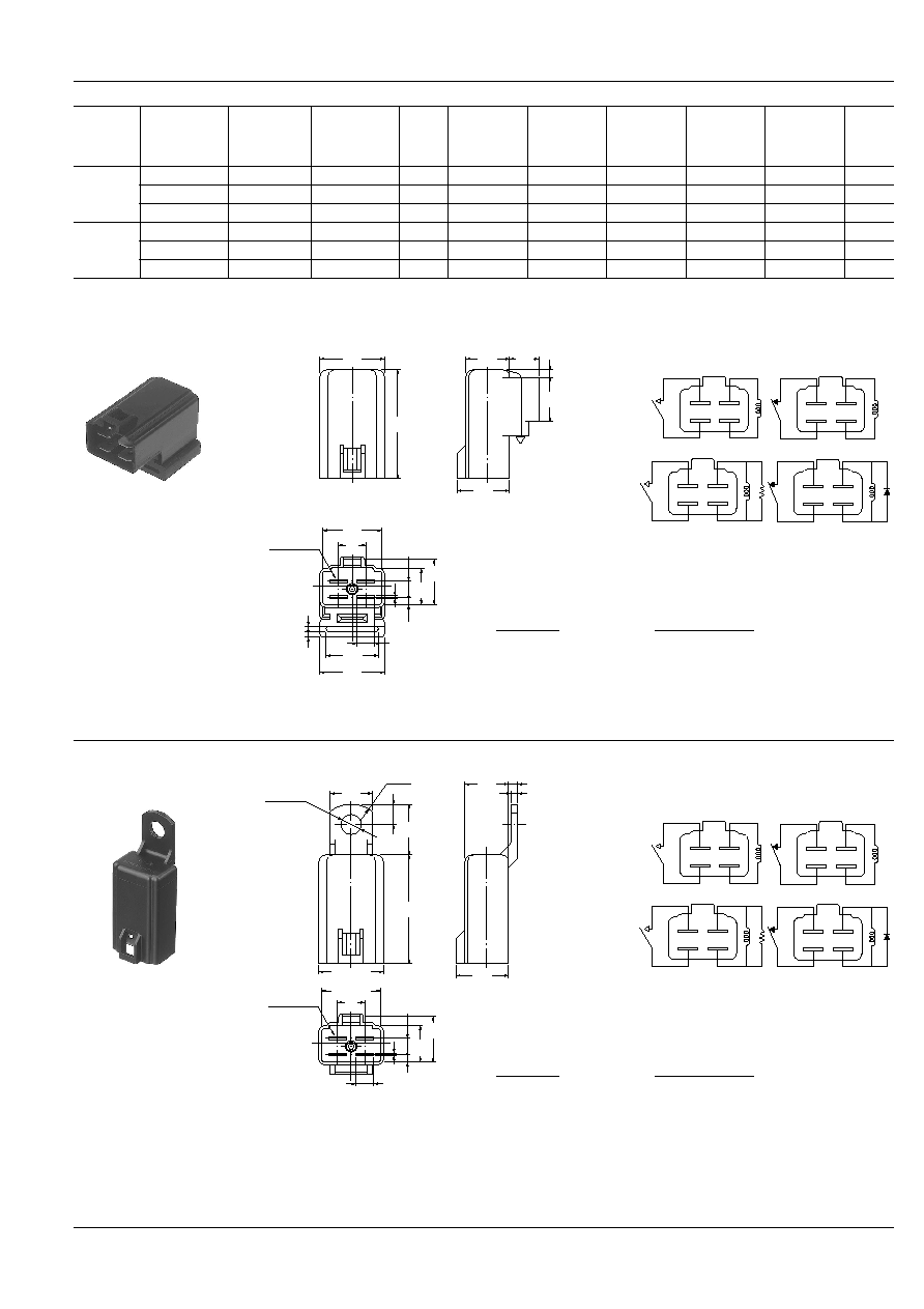
DIMENSIONS
1. 1 Form A/1 Form B
Rubber bracket A type
Contact
arrangement
Mounting type
Plastic sealed
type
Dust cover type
Nominal
voltage,
V DC
Pick-up voltage,
V DC (max.)
(at 20
∞
C
68
∞
F
)
Drop-out
voltage, V DC
(min.)
(at 20
∞
C
68
∞
F
)
Nominal oper-
ating current,
mA (
±
10%)
(at 20
∞
C
68
∞
F
)
Coil resistance,
(
±
10%) (at
20
∞
C
68
∞
F
)
Nominal
operating
power, mW
(at 20
∞
C
68
∞
F
)
Usable
voltage
range, V
DC
1 Form A
Rabber bracket A CA1aS-12V-A-5
CA1aFS-12V-A-5
12
8
0.6 to 6
120
100
1.4
10 to 16
Screw-mounting
CA1aS-12V-N-5
CA1aFS-12V-N-5
12
8
0.6 to 6
120
100
1.4
10 to 16
Direct coupling
CA1aS-12V-C-5
CA1aFS-12V-C-5
12
8
0.6 to 6
120
100
1.4
10 to 16
1 Form B
Rabber bracket A CA1bS-12V-A-5
CA1bFS-12V-A-5
12
8
0.6 to 6
120
100
1.4
10 to 16
Screw-mounting
CA1bS-12V-N-5
CA1bFS-12V-N-5
12
8
0.6 to 6
120
100
1.4
10 to 16
Direct coupling
CA1bS-12V-C-5
CA1bFS-12V-C-5
12
8
0.6 to 6
120
100
1.4
10 to 16
21.5
.846
19.5
.768
9
.354
37
1.457
14.4
.567
17.4
.685
10
.394
15
.591
2.5
.098
6
.236
21.5
.846
17
.669
0.8
.031
15.4
.606
12.4
.488
5.5
.217
2.4
.094
1.5
.059
2
.079
Sealed with
epoxy resin
Dimension:
General tolerance
Max. 1mm
.039 inch
:
±
0.1
±
.004
1 to 3mm
.039 to .118 inch
:
±
0.2
±
.008
Min. 3mm
.118 inch
:
±
0.3
±
.012
mm
inch
SCHEMATIC (Bottom View)
1 Form A
Including load
(1 Form A)
Including diode
(1 Form C)
1 Form B
Including diode type, including load type also available.
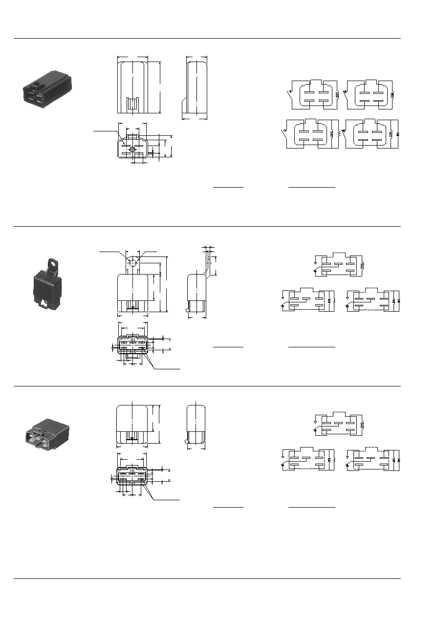
2. 1 Form A/1 Form B
Screw-mounting type
14
.551
9
.354
2
.079
17.4
.685
21.5
.846
3
.118
14.4
.567
6
.236
0.8
.031
15.4
.606
12.4
.488
5.5
.217
2.4
.094
17.5
.689
37
1.457
7
.276
R10
6.5
dia. hole
+0.3
≠
0
.256
dia.
+.012
≠
0
Sealed with
epoxy resin
19.5
.768
Dimension:
General tolerance
Max. 1mm
.039 inch
:
±
0.1
±
.004
1 to 3mm
.039 to .118 inch
:
±
0.2
±
.008
Min. 3mm
.118 inch
:
±
0.3
±
.012
SCHEMATIC (Bottom View)
1 Form A
Including load
(1 Form A)
Including diode
(1 Form C)
1 Form B
Including diode type, including load type also available.
CA
386
3. 1 Form A/1 Form B
Direct coupling type
21.5
.846
9
.354
17.4
.685
14.4
.567
6
.236
0.8
.031
15.4
.606
12.4
.488
5.5
.217
2.4
.094
37
1.457
Sealed with
epoxy resin
19.5
.768
Dimension:
General tolerance
Max. 1mm
.039 inch
:
±
0.1
±
.004
1 to 3mm
.039 to .118 inch
:
±
0.2
±
.008
Min. 3mm
.118 inch
:
±
0.3
±
.012
mm
inch
SCHEMATIC (Bottom View)
1 Form A
Including load
(1 Form A)
Including diode
(1 Form C)
1 Form B
Including diode type, including load type also available.
4. 1 Form C
Screw-mounting type
14
.551
23.4
.921
19.4
.764
31.2
1.228
4
.157
2
.079
5.5
.217
2.4
.094
0.8
.031
12.2
.480
12
.472
40
1.575
59
2.323
28
1.102
R10
6.6 dia. hole
.260 dia.
28.4
1.118
20
.787
9
.354
9
.354
6
.236
11.4
.449
Sealed with
epoxy resin
Dimension:
General tolerance
Max. 1mm
.039 inch
:
±
0.1
±
.004
1 to 3mm
.039 to .118 inch
:
±
0.2
±
.008
Min. 3mm
.118 inch
:
±
0.3
±
.012
SCHEMATIC (Bottom View)
Including diode type, including load type also available.
Including load
(1 Form C)
Including diode
(1 Form A)
1 Form C
5. 1 Form C
Direct coupling type
19.4
.764
5.5
.217
2.4
.094
0.8
.031
12.2
.480
40
1.575
28
1.102
9
.354
9
.354
6
.236
11.4
.449
Sealed with
epoxy resin
23.4
.921
31.2
1.228
28.4
1.118
Dimension:
General tolerance
Max. 1mm
.039 inch
:
±
0.1
±
.004
1 to 3mm
.039 to .118 inch
:
±
0.2
±
.008
Min. 3mm
.118 inch
:
±
0.3
±
.012
SCHEMATIC (Bottom View)
Including diode type, including load type also available.
Including load
(1 Form C)
Including diode
(1 Form A)
1 Form C

CA
387
REFERENCE DATA
1. Coil temperature rise
Tested sample: CA1aS-12V-N-5, 5 pcs.
Point measured: Inside the coil
Contact carrying current: 20A
Ambient temperature: Room temperature,
85
∞
C
185
∞
F
2. Electrical life test (Motor load)
Tested sample: CA1a-12V-N-5, 5 pcs.
Load: Steady 30A, Inrush 150A, 12V DC
Operate frequency: ON 3s, OFF 15s
Ambient temperature: Room temperature
12
14
16
140
120
100
80
60
40
20
0
85
∞
C
185
∞
F
Room
temperature
Temperature rise,
∞
C
Coil applied voltage, V
0
2
4
6
8
10
0
2
X
X
Max.
Max.
Min.
Min.
Pick-up and drop-out voltage, V
No. of operations,
◊
10
4
Contact welding: 0 times
Miscontact: 0 times
Pick-up voltage
Drop-out voltage
For Cautions for use, see Relay Technical Information (Page 48 to 76).
9/1/2000
All Rights Reserved, © Copyright Matsushita Electric Works, Ltd.
Go To Online Catalog