379
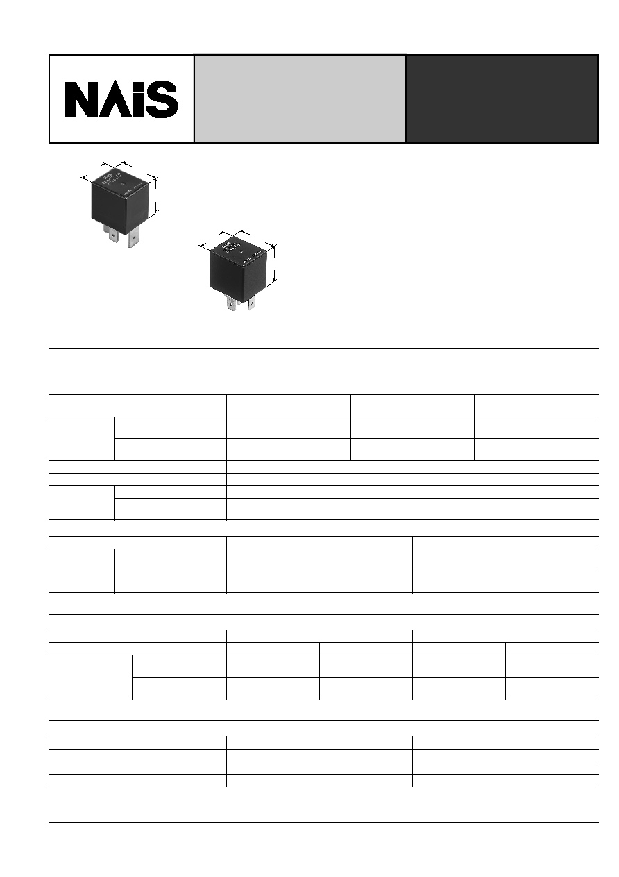
CB-RELAYS
HIGH POWER
AUTOMOTIVE RELAY
22.0
.866
25.5
1.004
26.5
1.043
mm
inch
22.0
.866
25.0
.984
26.0
1.024
FEATURES
∑ 40 A rating at 85
∞
C
185
∞
F
∑ ISO type terminals
∑ High shock resistance for drop test requirements
(2 meters
6.6 feet
)
∑ Low temperature rise -- all current carrying material
is copper.
∑ Quick connect and PC board type
SPECIFICATIONS
Contact
(1) Standard type (12V coil voltage)
(2) Standard type (24V coil voltage)
*
1
All other specifications are the same as those of standard type (12V coil voltage)
Arrangement
1 Form A
1 Form C
High contact capacity
(1 Form A)
Rating
Nominal switching capacity
40 A 14 V DC
N.O.: 40 A 14 V DC
N.C.: 30 A 14 V DC
70 A 14 V DC (at 20
∞
C
68
∞
F
)
50 A 14 V DC (at 85
∞
C
185
∞
F
)
Max. switching current
(at 85
∞
C
185
∞
F
)
40 A 14 V DC
N.O.: 40 A 14 V DC
N.C.: 30 A 14 V DC
40 A 14 V DC
Initial contact resistance, max.
15m
Contact material
Silver alloy
Expected life
Mechanical (at 120 cpm)
Min. 10
6
Electrical (at rated load)
Flux-resistant type: Min. 10
5
*
1
Sealed type: Min. 5
◊
10
4
Arrangement
1 Form A
1 Form C
Rating
Nominal switching capacity
20 A 28V DC
N.O.: 20 A 28 V DC
N.C.: 10 A 28 V DC
Max. switching current
(at 85
∞
C
185
∞
F
)
20 A 28 V DC
N.O.: 20 A 28 V DC
N.C.: 10 A 28 V DC
(3) Heat resistant type (12V, 24V coil voltage)
*
1
All other specifications are the same as those of standard type (12V coil voltage)
Type
12V coil voltage
24V coil voltage
Arrangement
1 Form A
1 Form C
1 Form A
1 Form C
Rating
Nominal switching
capacity
35 A 14V DC
N.O.: 35 A 14 V DC
N.C.: 30 A 14 V DC
20 A 28 V DC
N.O.: 20 A 28 V DC
N.C.: 10 A 28 V DC
Max. switching current
(at 85
∞
C
185
∞
F
)
35 A 14 V DC
N.O.: 35 A 14 V DC
N.C.: 30 A 14 V DC
20 A 28V DC
N.O.: 20 A 28 V DC
N.C.: 10 A 28 V DC
Coil
Arrangement
Coil voltage
Nominal operating power
1 Form A,
1 Form C
12V DC
1.4W
24V DC
1.8W
High contact capacity
12V DC
1.8W

CB
380
Characteristics
Remarks
* Specifications will vary with foreign standards certification ratings.
*
1
All other specifications are the same as those of standard type (12V coil voltage)
*
2
Measurement at same location as "Initial breakdown voltage" section
*
3
Detection current: 10 mA
*
4
Wave is standard shock voltage of
±
1.2
◊
50
µ
s according to JEC-212-1981
*
5
Excluding contact bounce time
*
6
Half-wave pulse of sine wave: 11ms; detection time: 10
µ
s
*
7
Half-wave pulse of sine wave: 6ms
*
8
Detection time: 10
µ
s
*
9
Refer to 5. Conditions for operation, transport and storage mentioned in
AMBIENT ENVIRONMENT (Page 61)
Max. operating speed (at rated load)
15 cpm
Initial insulation resistance*
2
Min. 20 M
(at 500 V DC)
Initial breakdown voltage*
3
Between open contacts
500 Vrms for 1 min.
Between contacts and coil
500 Vrms for 1 min.
Operate time*
4
(at nominal voltage)
Max. 15 ms
Release time (without diode)*
4
(at nominal voltage)
Max. 15 ms
Shock resistance
Functional*
5
Min. 200 m/s
2
{20 G}
Destructive*
6
Min. 1,000 m/s
2
{100 G}
Vibration resistance
Functional*
7
10 to 500Hz, Min. 44.1m/s
2
{4.5G}
Functional*
8
10 to 2,000Hz, Min. 44.1m/s
2
{4.5G}
Conditions for operation, transport and storage*
9
(Not freezing and condensing at low temperature)
Ambient temp.
≠40
∞
C to +85
∞
C
≠40
∞
F to +185
∞
F
(Heat resistant type: ≠40
∞
C to +125
∞
C
≠40
∞
F to +257
∞
F
)
Humidity
5 to 85% R.H.
Unit weight
Approx. 33 g
1.16 oz
TYPICAL APPLICATIONS
∑ Automotive system
∑ ABS, Head Lamp, Air conditioner
∑ Tracter, Combine
ORDERING INFORMATION
1
F
R
T
M
12 V
CB
Contact arrangement
Protective construction
Type classification
Mounting classification
Coil voltage (DC)
1a: 1 Form A
1: 1 Form C
1aH: High contact
capacity*
1
(1 Form A)
Nil: Sealed type
F: Flux-resistant type
Heat resistant of types
Nil: Standard type
T: Heat resistant type*
2
Nil: Standard type
D: with diode inside
R: with resistor inside
Nil: Quick connect type
P: PC board type
M:Bracket type
12, 24 V
Note: Bulk pakage: 50 pcs.; Case: 200 pcs.
*1 High contact capacity type is available only for "Quick connect" and 12 V.
(See "1. Standard type in TYPES" Page 380)
*2 Heat resistant type with high contact capacity is not available.
(See "2. Heat resistant type in TYPES" Page 381)
TYPES
1. Standard type
Contact arrangement
Mounting classification
Coil voltage, V DC
Part No.
Sealed type
Flux-resistant type
1 Form A
PC board type
12V
CB1a-P-12V
CB1aF-P-12V
24V
CB1a-P-24V
CB1aF-P-24V
Quick connect type
12V
CB1a-12V
CB1aF-12V
24V
CB1a-24V
CB1aF-24V
Bracket type
12V
CB1a-M-12V
CB1aF-M-12V
24V
CB1a-M-24V
CB1aF-M-24V
1 Form C
PC board type
12V
CB1-P-12V
CB1F-P-12V
24V
CB1-P-24V
CB1F-P-24V
Quick connect type
12V
CB1-12V
CB1F-12V
24V
CB1-24V
CB1F-24V
Bracket type
12V
CB1-M-12V
CB1F-M-12V
24V
CB1-M-24V
CB1F-M-24V
High contact capacity (1 Form A)
Quick connect type
12V
CB1aH-12V
CB1aHF-12V
CB
381
2. Heat resistant type
COIL DATA
(at 20
∞
C
68
∞
F
)
DIMENSIONS
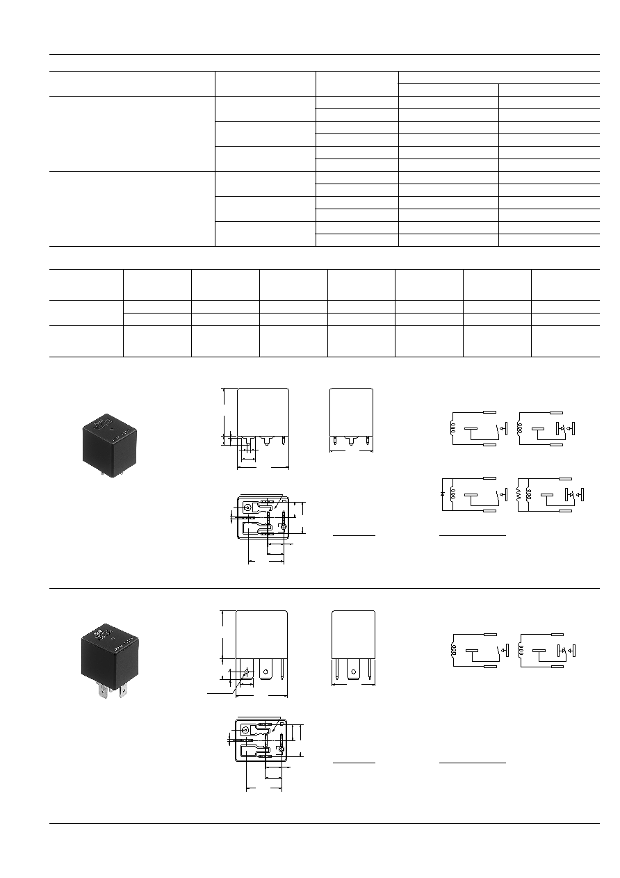
1. PC board type
Contact arrangement
Mounting classification
Coil voltage, V DC
Part No.
Sealed type
Flux-resistant type
1 Form A
PC board type
12V
CB1a-T-P-12V
CB1aF-T-P-12V
24V
CB1a-T-P-24V
CB1aF-T-P-24V
Quick connect type
12V
CB1a-T-12V
CB1aF-T-12V
24V
CB1a-T-24V
CB1aF-T-24V
Bracket type
12V
CB1a-T-M-12V
CB1aF-T-M-12V
24V
CB1a-T-M-24V
CB1aF-T-M-24V
1 Form C
PC board type
12V
CB1-T-P-12V
CB1F-T-P-12V
24V
CB1-T-P-24V
CB1F-T-P-24V
Quick connect type
12V
CB1-T-12V
CB1F-T-12V
24V
CB1-T-24V
CB1F-T-24V
Bracket type
12V
CB1-T-M-12V
CB1F-T-M-12V
24V
CB1-T-M-24V
CB1F-T-M-24V
Contact
arrangement
Nominal
voltage,
V DC
Pick-up voltage,
V DC (max.)
Drop-out
voltage,
V DC (mim.)
Nominal
current,
mA (
±
10%)
Coil resistance,
(
±
10%)
Nominal
operating power,
W
Usable voltage
range,
V DC
1 Form A
1 Form C
12
3 to 7
1.2 to 4.2
117
103
1.4
10 to 16
24
6 to 14
2.4 to 8.4
75
320
1.8
20 to 32
High contact
capacity
(1 Form A)
12
3 to 7
1.2 to 4.2
150
80
1.8
10 to 16
mm
inch
22.0
.866
26.0
1.024
2.15
.085
6.3
.248
4.5
.177
1.0
.039
25.0
.984
Venting
hole
Sealed by epoxy resin
0.8
.031
8.4
.331
16.8
.661
2.6
.102
17.9
.705
8.0
.315
8.4
.331
86
87a*
87
30
85
Dimension:
General tolerance
Max. 1mm
.039 inch
:
±
0.1
±
.004
1 to 3mm
.039 to .118 inch
:
±
0.2
±
.008
Min. 3mm
.118 inch
:
±
0.3
±
.012
Schematic (Bottom view)
86
30
87
87a
85
86
Including diode
(1 Form A)
Including load
(1 Form C)
87
85
86
87
87a
85
86
1a
1c
87
85
Including diode type, including load type also available.
2. Quick connect type
25.0
.984
11.0
.433
5-6.3
5-.248
26.0
1.024
22.0
.866
4.0
.157
1.7 dia.
.067 dia.
Venting
hole
Sealed by epoxy resin
0.8
.031
8.4
.331
16.8
.661
2.6
.102
17.9
.705
8.0
.315
8.4
.331
86
87a*
87
30
85
Dimension:
General tolerance
Max. 1mm
.039 inch
:
±
0.1
±
.004
1 to 3mm
.039 to .118 inch
:
±
0.2
±
.008
Min. 3mm
.118 inch
:
±
0.3
±
.012
Schematic (Bottom view)
86
87
87a
85
86
1a
1c
87
85
Including diode type, including load type also available.
CB
382
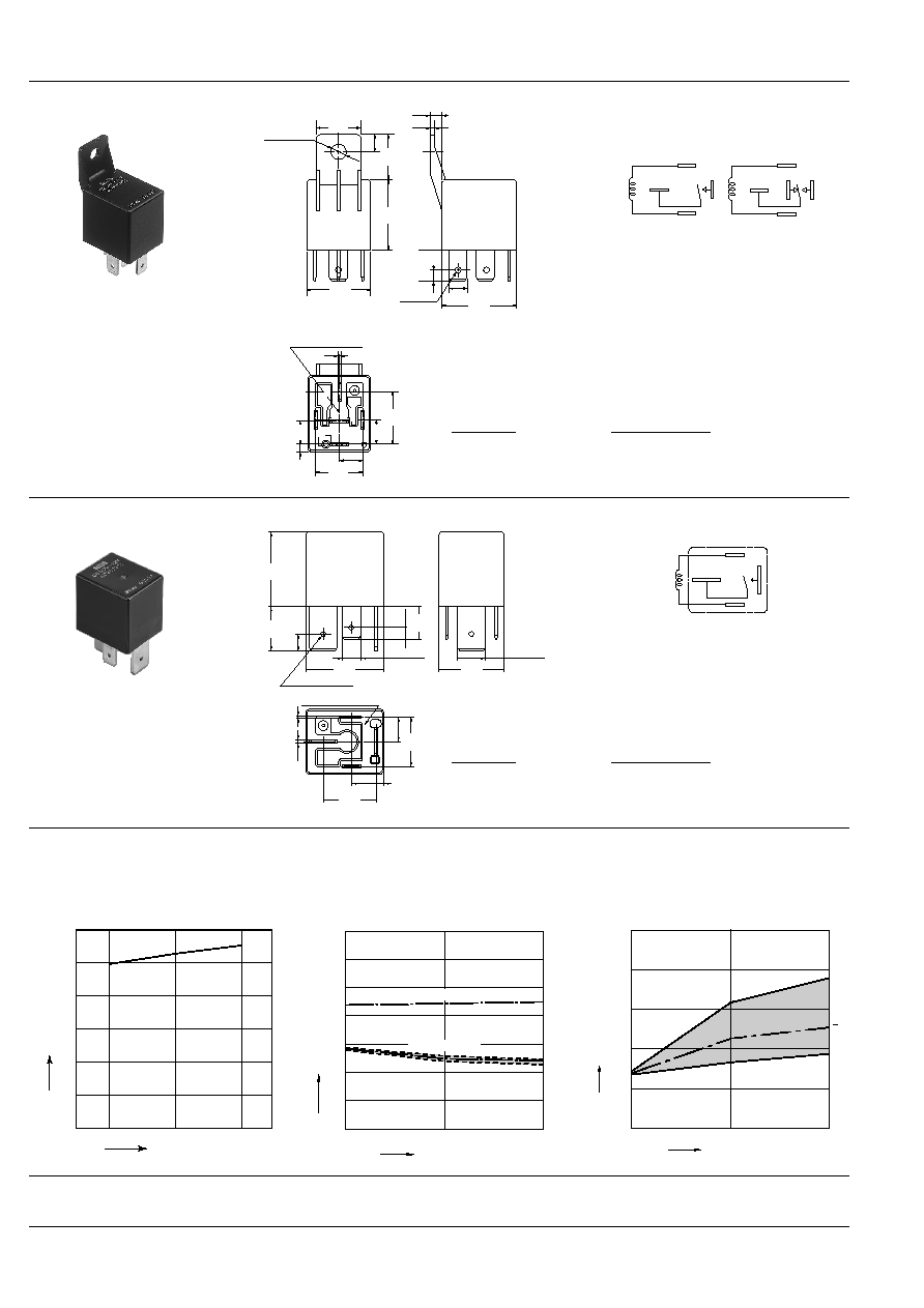
3. Bracket type
mm
inch
16.0
.630
6.0
.236
25.0
.984
16.0
.630
4.0
±
0.1
.157
±
.004
1.7
.067
5.4
±
0.1 dia.
.213
±
.004
22.0
.866
11.0
.433
5-6.3
5-.248
26.0
1.024
4.0
.157
1.7 dia.
.067 dia.
8.0
±
0.1
.315
±
.004
17.9
.705
Sealed by epoxy resin
0.8
.031
8.4
.331
2.6
.102
8.4
.331
16.8
.661
86
87
a*
87
30
85
Dimension:
General tolerance
Max. 1mm
.039 inch
:
±
0.1
±
.004
1 to 3mm
.039 to .118 inch
:
±
0.2
±
.008
Min. 3mm
.118 inch
:
±
0.3
±
.012
Schematic (Bottom view)
86
87
87a
85
86
1a
1c
87
85
Including diode type, including load type also available.
4. High contact capacity type
2-6.3
±
0.08
2-.248
±
.003
4-1.7 dia. hole
4-.067 dia. hole
2-9.5
±
0.08
2-.374
±
.003
87
30
85
86
16.8
.661
8.4
.331
2.6
.102
0.8
.031
1.2
.047
8.4
.331
17.9
.705
22.0
.866
26.5
1.043
11.0
.433
15.0
.591
25.5
1.004
4.0
.157
5.8
.228
Sealed by epoxy resin
Dimension:
General tolerance
Max. 1mm
.039 inch
:
±
0.1
±
.004
1 to 3mm
.039 to .118 inch
:
±
0.2
±
.008
Min. 3mm
.118 inch
:
±
0.3
±
.012
Schematic (Bottom view)
87
85
30
86
REFERENCE DATA
1. Coil temperature rise
Tested sample: CB1aF-P-12V, 3pcs.
Ambient temperature: 85
∞
C
185
∞
F
Contact carrying current: 40A
2. Electrical life test (Motor load)
Tested sample: CB1a-12V, 3pcs.
Load: 18A steady, Inrush 82A
Operating frequency: ON 2s, OFF 6s
Coil applied voltage, V
Temperature rise,
∞
C
12
14
16
180
150
120
90
60
30
0
40A
No. of operations,
◊
10
4
10
5
0
0
5
6
7
4
3
2
1
Max.
Min.
x
≠
x
≠
Drop-out voltage
Pick-up voltage
Pick-up and drop-out voltage, V
Contact welding: 0 times
Miscontact: 0 times
0
0
1
2
3
4
5
10
5
Max.
Min.
x
No. of operations,
◊
10
4
Contact resistance, m
For Cautions for use, see Relay Technical Information (Page 48 to 76).
9/1/2000
All Rights Reserved, © Copyright Matsushita Electric Works, Ltd.
Go To Online Catalog