CP
352
CP-RELAYS
ULTRA-MINIATURE,
LOW PROFILE
AUTOMOTIVE RELAY
mm
inch
*Surface mount terminal type is coming soon.
9.5
.374
13
.512
14
.551
9.5
.374
13
.512
14
.551
FEATURES
∑ Low profile
<Height>
PC board terminal type: 9.5 mm
.374 inch
Surface-mount terminal type: 10.5mm
.413inch
∑ High capacity
CP Relay provides low profile spacesav-
ing advantages while offering high contin-
uous current of 25 A(1 hour).
∑ Sealed construction suitable for
harsh environments
∑ Simple footprint pattern enables ease
of PC board layout
∑ "PC board terminal" and "Surface
mount terminal" types available
Contact terminals
Coil terminals
SPECIFICATIONS
Contact
Coil
Characteristics
Arrangement
1 Form A
1 Form C
Contact material
Silver alloy
Initial contact resistance, max.
(By voltage drop 6V DC 1A)
100 m
Rating
Nominal switching
capacity
20 A 14 V DC
20 A 14 V DC
(N.O.)
10 A 14 V DC
(N.C.)
Max. switching voltage
16 V DC
Max. carrying current
40 A for 2 minutes
30 A for 1 hour
(12 V at 20
∞
C
68
∞
F
)
35 A for 2 minutes
25 A for 1 hour
(12 V at 85
∞
C
185
∞
F
)
Expected
life (min.
operations)
Mechanical (at 120cpm)
10
7
Electrical
(at 6cpm)
Resistive load
Min. 10
5
*
1
Motor load
Min. 2
◊
10
5
*
2
Min. 10
5
*
3
Lamp load
Min. 10
5
*
4
Nominal operating power
640 mW
Max. operating speed (at rated load)
6cpm
Initial insulation resistance*
5
Min. 100M
(at 500 V DC)
Initial breakdown
voltage*
6
Between open
contacts
500 Vrms for 1min.
Between contact
and coil
500 Vrms for 1min.
Operate time*
7
Max. 10ms (at 20
∞
C
68
∞
F
)
Release time (without diode)*
7
(at nominal voltage)
Max. 10ms (at 20
∞
C
68
∞
F
)
Shock resistance
Functional*
8
Min. 100 m/s
2
{10 G}
Destructive*
9
Min. 1,000 m/s
2
{100 G}
Vibration resistance
Functional*
10
10 to 100 Hz,
Min.44.1 m/s
2
{4.5 G}
Destructive
10 to 500 Hz,
Min.44.1 m/s
2
{4.5 G}
Conditions in case of
operation, transport
and storage*
11
(Not freezing and
condensing at low
temperature)
Ambient temp
≠40 to +85
∞
C
≠40 to +185
∞
F
Humidity
5 to 85% R.H.
Unit weight
Approx. 4g
.14 oz
Remarks
*
Specifications will vary with foreigh standards certification ratings.
*
1
At nominal switching capacity, operating frequency: 1s ON, 9s OFF
*
2
N.O.: at 5A (steady), 25A (inrush)/N.C.: at 20A (brake) 14V DC, operating
frequency: 0.5s ON, 9.5s OFF
*
3
At 20A 14V DC (Motor lock), operating frequency: 0.5s ON, 9.5s OFF
*
4
N.O.: at 5A (steady), 40A (inrush)14V DC, operating frequency: 1s ON, 14s OFF
*
5
Measurement at same location as "Intial breakdown voltage" section
*
6
Detection current: 10mA
*
7
Excluding contact bounce time
*
8
Half-wave pulse of sine wave: 11ms; detection time: 10
µ
s
*
9
Half-wave pulse of sine wave: 6ms
*
10
Detection time: 10
µ
s
*
11
Refer to 5. Conditions for operation, transport and storage mentioned in
AMBIENT ENVIRONMENT (Page 61)
TYPICAL
APPLICATIONS
∑ Power windows
∑ Auto door lock
∑ Power sunroof
∑ Hazard flasher
∑ Flasher
∑ Defogger
∑ Power steering
∑ Power seat
ORDERING INFORMATION
Ex. CP
Contact
arrangement
1a:
1:
1 Form A
1 Form C
Nil:
X:
Z:
Tube packing
Tape and reel packing
(picked from the NC terminal side)
Tape and reel packing
(picked from the coil terminal side)
12 V
Packing style
Coil voltage
(DC)
1a
12V
Nil:
SA:
PC board terminal
Surface-mount
terminal*
Mounting classification
SA
X
Notes: 1. Standard packing: Carton (Tube): 40 pcs.; Case: 1,000 pcs.
2. Tape and reel packing: Carton (Tape and reel): 300 pcs.; Case: 900 pcs.
3. Surface-mount terminal type are available only for tape and reel packing.
4. 24 V DC type is also available. Please consult us for details.
*Only for 1 Form C type
CP
353
TYPES
1. PC board terminal type
2. Surface mount terminal type
Notes:
1. Tape and reel (picked from N.C. terminal side) is also available by request.
Part No. suffix "-x" is needed when ordering. (ex) CP1SA-12V-X
2. Tape and reel packing symbol "-z" or "-x" are not marked on the relay.
3. 24 V DC type is also available. Please consult us for details.
Contact arrangement
Coil voltage
Part No.
1 Form A
12 V DC
CP1a-12V
1 Form C
12 V DC
CP1-12V
Contact arrangement
Coil voltage
Part No.
1 Form C
12 V DC
CP1SA-12V-Z
COIL DATA
(at 20
∞
C
68
∞
F
)
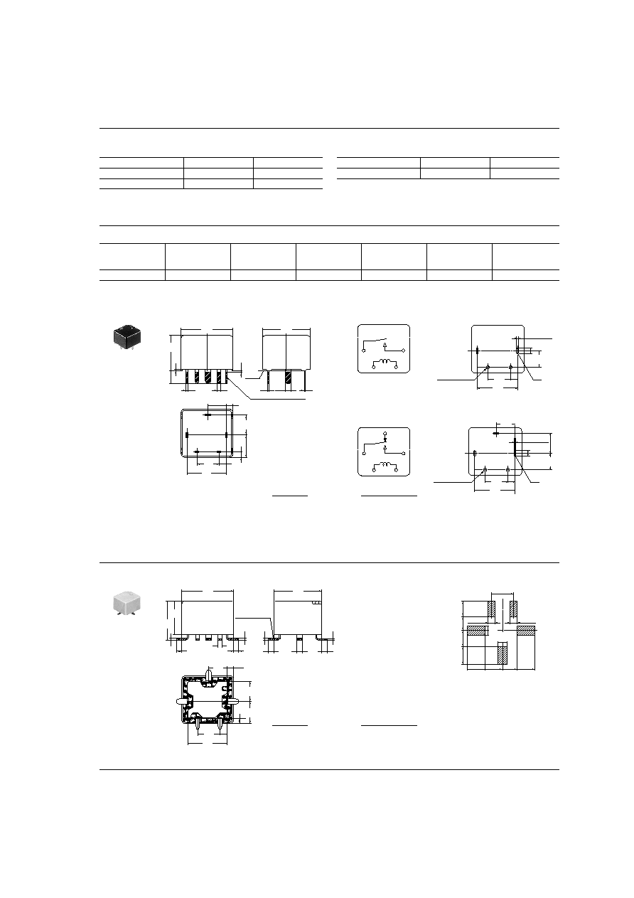
DIMENSIONS
1. PC board terminal type
Nominal voltage,
V DC
Pick-up voltage,
V DC (max.)
Drop-out voltage,
V DC (min.)
Coil resistance
(
±
10%)
Nominal operating
current
mA (
±
10%)
Nominal operating
power
mW
Usable voltage
range,
V DC
12
(initial) 7.2
(initial) 1.0
225
53.3
640
10 to 16
Max.
1.0
.039
1.0
.039
3.5
.138
0.4
.016
0.4
.016
0.4
.016
1.5
.059
0.3
.012
1.7
.067
2.0
.079
1.5
.059
5.0
.197
6.0
.236
A*
Pre-soldering
14.0
.551
13.0
.512
5.4
.213
9.5
.374
6.0
.236
10.7
.421
* Dimensions (thickness and width) of terminal specified in this catalog is measured before pre-soldering.
Intervals between terminals is measured at A surface level.
mm
inch
2. Surface mount terminal type
Pre-soldering
1.7
.067
1.4
.055
1.4
.055
1.5
.059
1.5
.059
1.5
.059
1
.039
2
.079
13.0
.512
0.3
.012
0.4
.016
0.4
.016
0.4
.016
14.0
.551
9.1
.358
10.5
.413
5
.197
5.4
.213
1.5
.059
6.0
.236
6.0
.236
10.7
.421
Dimension:
General tolerance
Max. 1mm
.039 inch
:
±
0.1
±
.004
1 to 3mm
.039 to .118 inch
:
±
0.2
±
.008
Min. 3mm
.118 inch
:
±
0.3
±
.012
Recommendable mounting pad
(Top view)
6.0
.236
2.0
.079
2.0
.079
2.5
.098
2.5
.098
4.8
.189
4.0
.157
4.7
.185
4.8
.189
4.8
.189
4.4
.173
3.8
.150
4.2
.165
Schematic (Bottom view)
1a
1c
COM
COIL
NO
NC
NO
COIL
COM
PC board pattern (Bottom view)
1a
1c
2-1.3+0.1 dia.
2-.051+.004 dia.
4.5
.177
2
.079
(R)
10.7
.421
2-0.9+0.1
2-.035+.004
2-2.0+0.1
2-.079+.004
6
.236
5.4
.213
2-1.3+0.1 dia.
2-.051+.004 dia.
4.5
.177
2
.079
(R)
10.7
.421
2-0.9+0.1
2-.035+.004
2-2.0+0.1
2-.079+.004
6
.236
5
.197
Dimension:
General tolerance
Max. 1mm
.039 inch
:
±
0.1
±
.004
1 to 3mm
.039 to .118 inch
:
±
0.2
±
.008
Min. 3mm
.118 inch
:
±
0.3
±
.012
CP
5
354
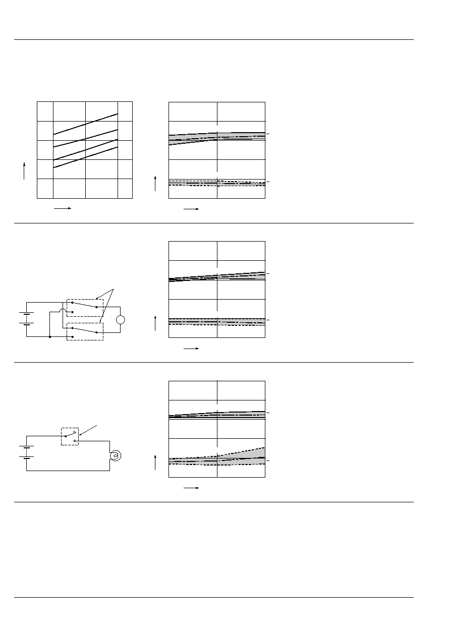
REFERENCE DATA
1. Coil temperature rise
Tested sample : CP1-12V, 6pcs
Point measured : Inside the coil
Contact carrying current, 5A, 10A, 15A, 20A
Resistance method, ambient temperature 85
∞
C
185
∞
F
2-(1). Electrical life test (at rated load)
Tested Sample : CP1-12V
Quantity : n = 4 (NC = 2, NO = 2)
Load : Resisitive load (NC side : 10A 14 V DC, NO
side : 20 A 14 V DC)
Operating frequency : ON 1s, OFF 9s
Contact welding : 0 time
Miscontact : 0 time
12
14
16
100
80
60
40
20
0
20A
15A
10A
5A
Coil applied voltage, V
Temperature rise,
∞
C
0
2
4
6
8
10
0
5
10
Pick-up voltage
Drop-out voltage
X
X
Max.
Max.
Min.
Min.
Pick-up and drop-out voltage, V
No. of operations,
◊
10
4
Contact welding: 0 times
Miscontact: 0 times
2-(2). Electrical life test (Motor free)
Tested Sample : CP1-12V, 3pcs.
Load : 5A, Inrush 25A, Brake
current 15A, Power
window motor load (Free condition).
Operating frequency : ON 0.5s, OFF 9.5s
Circuit :
Contact welding : 0 time
Miscontact : 0 time
Sample
M
0
2
4
6
8
10
0
10
20
Pick-up voltage
Drop-out voltage
X
X
Max.
Max.
Min.
Min.
Pick-up and drop-out voltage, V
No. of operations,
◊
10
4
Contact welding: 0 times
Miscontact: 0 times
2-(3). Electrical life test (Lamp load)
Tested sample : CP1-12V, 3pcs.
Load : 5A, Inrush 40A, 14VDC lamp load
Operating frequency : ON 1s, OFF 14s
Circuit :
Contact welding : 0 time
Miscontact : 0 time
Sample
Lamp
0
2
4
6
8
10
0
5
10
Pick-up voltage
Drop-out voltage
X
X
Max.
Max.
Min.
Min.
Pick-up and drop-out voltage, V
No. of operations,
◊
10
4
Contact welding: 0 times
Miscontact: 0 times
For Cautions for use, see Relay Technical Information (Page 48 to 76).
5
/
27
/200
2
All Rights Reserved, © Copyright Matsushita Electric Works, Ltd.
Go To Online Catalog