110
HE RELAYS
TV-15, 30 AMP (1 Form A)
Power Relay
VDE
mm
inch
33
1.299
35.8
1.409
50
1.969
FEATURES
∑ High contact capacity with superior inrush current characteristics;
∑ Excellent high heat-resistance;
∑ High dielectric strength: 10,000 V surge Conforming to VDE0806
(Insulation gap: 8 mm
.315 inch
) VDE, TÐV also approved
1 Form A
2 Form A
Rating
30 A 277 V AC
25 A 277 V AC
TV rating
TV-15
TV-10
SPECIFICATIONS
Contacts
Coil (at 20
∞
C
68
∞
F
)
Remarks
* Specifications will vary with foreign standards certification ratings.
*
1
Measurement at same location as "initial breakdown voltage" section
*
2
Detection current: 10 mA
*
3
Wave is standard shock voltage of
±
1.2
◊
50
µ
s according to JEC-212-1981
*
4
Excluding contact bounce time
*
5
Half-wave pulse of sine wave: 11ms; detection time: 10
µ
s
*
6
Half-wave pulse of sine wave: 6ms
*
7
Detection time: 10
µ
s
*
8
Refer to 5. Conditions for operation, transport and storage mentioned in
AMBIENT ENVIRONMENT (Page 24).
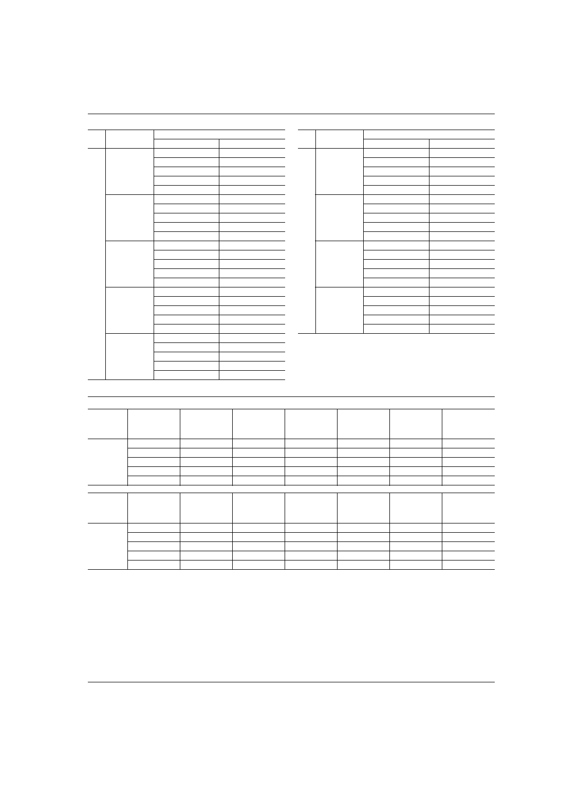
Characteristics
Type
DC coil type
AC coil type
Arrangement
1a
2a
1a
2a
Contact material
Silver alloy
Initial contact resistance, max.
(By voltage drop 6 V DC 1A)
100 m
Rating
(resistive)
Nominal
switching capacity
30 A
277 V
AC
25 A
277 V
AC
30 A
277 V
AC
25 A
277 V
AC
Max. switching
power
8,310
VA
6,925
VA
8,310
VA
6,925
VA
Max. switching
voltage
277 V AC, 30 V DC
Max. switching
current
30 A
25 A
30 A
25 A
Expected
life (min.
operations)
Mechanical
(at 180 cpm)
10
7
5
◊
10
6
Electrical
(at 20 cpm)
10
5
(1a: 30 A 277 V AC, 2a: 25 A 277 V AC)
2
◊
10
5
(1a: 30 A 250 V AC, 2a: 20 A 250 V AC)
DC coil type
AC coil type
Nominal operating power
1.92 W
See Coil data (next page)
DC coil type
AC coil type
Maximum operating speed
20 cpm
Initial insulation resistance*
1
Min. 1,000 M
at 500 V DC
Initial
breakdown
voltage*
2
Between open contacts
2,000 Vrms for 1 min.
Between contacts and
coil
5,000 Vrms for 1 min.
Between contact sets
(2a)
4,000 Vrms for 1 min.
Surge voltage between coil
and contact*
3
Min. 10,000 V
Operate time*
4
(at nominal voltage)
Approx. 20 ms
Release time*
4
(at nominal voltage)
Approx. 5 ms
Approx. 20 ms
Temperature rise, max.
(resistive load)(at 55
∞
C)
60
∞
C
65
∞
C
Shock resistance
Functional*
5
98 m/s
2
{10 G}
Destructive*
6
980 m/s
2
{100 G}
Vibration resistance
Functional*
7
10 to 55 Hz
at double amplitude of 1 mm
Destructive
10 to 55 Hz
at double amplitude of 1.5 mm
Conditions for opera-
tion, transport and
storage*
8
(Not freezing
and condensing at low
temperature)
Ambient
temp.
≠50
∞
C to +55
∞
C
≠58
∞
F to +131
∞
F
Humidity
5 to 85% R.H.
Air pressure
86 to 106 kPa
Unit weight
Approx. 90 g
3.17 oz
(Plug-in type)
TYPICAL
APPLICATIONS
1. Home appliances
∑ Air conditioners
∑ Microwave ovens
∑ TV sets
∑ Heaters
∑ Stereo
2. Office equipment
∑ Copiers
∑ Vending machines
ORDERING INFORMATION
HE
1a
N
S
DC12
V
Contact arrangement
1a: 1 Form A
2a: 2 Form A
N: 70% of nominal
voltage
Nil: Plug-in terminal type
S: Screw terminal type
SW: Screw terminal type
(wide pitch)
Q: NEMA terminal type
P: PC board terminal type*
DC: 6, 12, 24, 48,
110 V
AC: 12, 24, 48,
120, 240 V
Pick-up voltage
Terminals
Coil voltage
Standard packing: Carton: 20 pcs.; Case: 100 pcs.
* PC board terminal are available only for 1 Form A type of DC coil voltage.
UL/CSA, TÐV approved type is standard.
HE
113
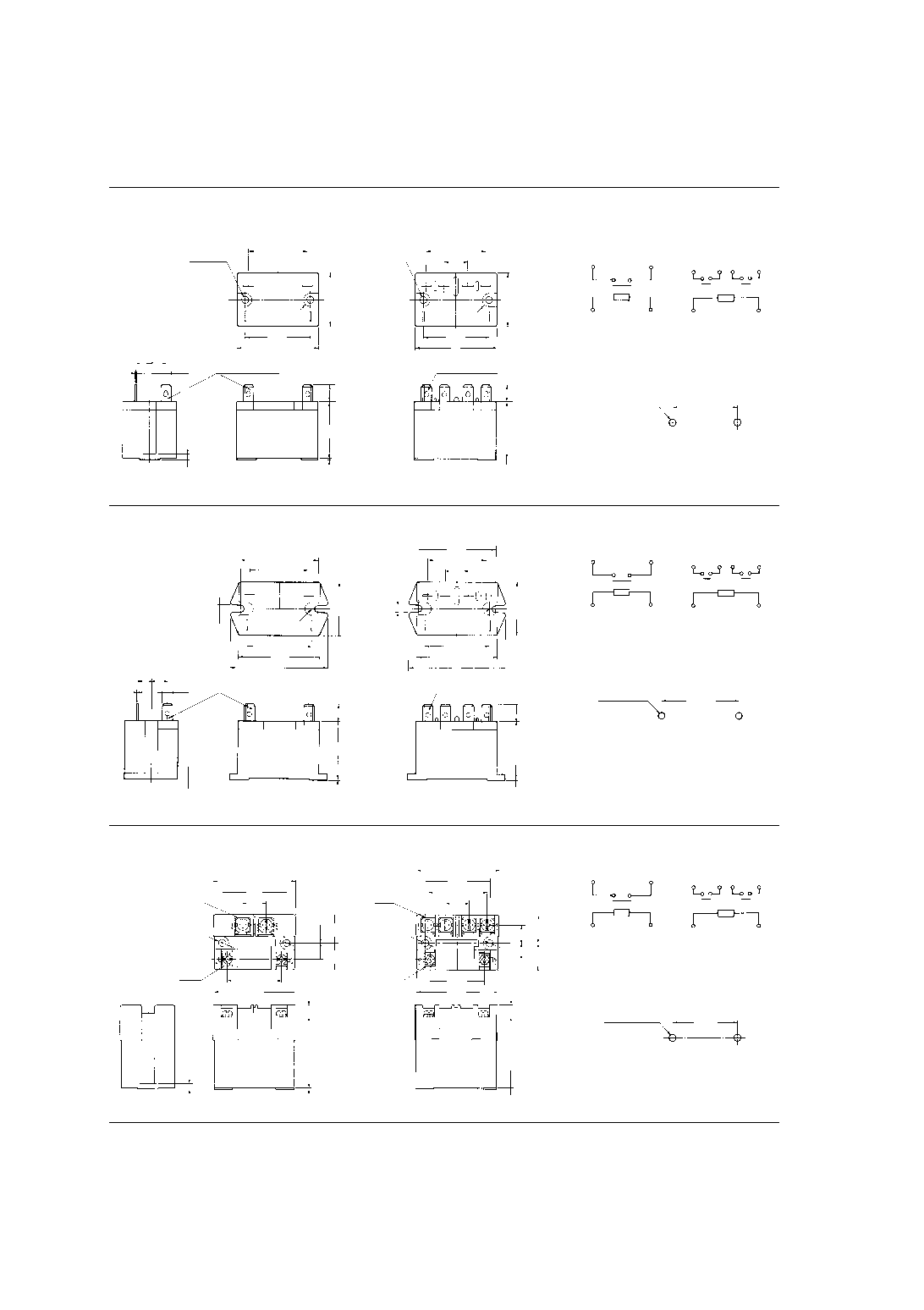
4. Screw terminal type (wide pitch)
1a
51.0
2.008
47.6
1.874
40.0
1.575
33.5
1.319
50.0
1.969
60
2.362
14.4
.567
4.5
.177
M4.5
M3.5
11.3
.445
10.25
.404
17.5
.689
16.5
.650
0.8
.031
3.5
.138
7.5
.295
44.5
1.752
R4
2a
General tolerance:
±
0.3
±
.012
33.5
1.319
50.0
1.969
60
2.362
51.0
2.008
47.6
1.874
40.0
1.575
36.4
1.433
14.4
.567
4.5
.177
M4.0
M3.5
0.8
.031
7.5
.295
44.5
1.752
11.3
.445
10.25
.404
17.5
.689
16.5
.650
R4
Schematic
1a
2a
1
4
6
5
1
2
3
4
6
5
Panel cutout
2-4.5
±
0.1 dia.
2-.177
±
.004
47.6
±
0.1
1.874
±
.004
mm
inch
5. PC board terminal type
38.0
1.496
33
1.299
36.3
1.429
0.5
.020
4
.157
4.7
.185
Schematic (Bottom view)
PC board pattern (Copper-side view)
1
4
6
5
32
1.259
24
.945
18.6
.732
8.4
.331
4.7
.185
6-2 dia.
6-.079 dia.
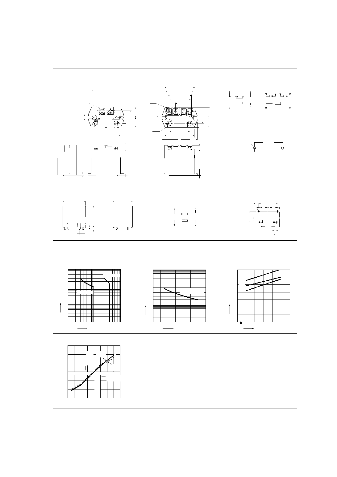
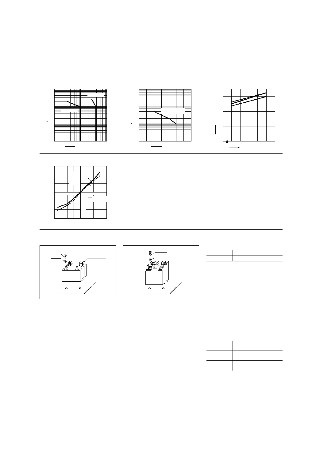
REFERENCE DATA
1 Form A Type
1. Maximum switching power
2. Life curve
3. Contact temperature rise (DC type)
Measured portion: Inside the coil
Contact current: 30 A
100
50
30
20
10
5
1
0.5
30
100
500 1,000
Contact voltage, V
Contact current, A
AC resistive
DC resistive
10
5
100
50
1,000
500
30
35
20
25
10
15
5
0
Contact current, A
No. of operations,
◊
10
4
250 V AC resistive
30 V DC resistive
70
60
50
40
30
20
10
0
100
110
120
20
∞
C
60
∞
C
Coil applied voltage, %V
Temperature rise,
∞
C
40
∞
C
4. Ambient temperature characteristics
Sample: HE1aN-AC120V, 6 pcs.
30
40
60
80
20
≠10
0
≠20
≠50
≠20
≠30
x
x-
-
Ambient
temperature,
∞
C
Rate of
change, %
Pick-up
voltage
Drop-out
voltage
20
10
HE
114
2 Form A Type
1. Maximum switching power
2. Life curve
3. Contact temperature rise (DC type)
Measured portion: Inside the coil
Contact current: 30 A
100
50
30
20
10
5
1
0.5
30
100
500 1,000
Contact voltage, V
Contact current, A
AC resistive
DC resistive
10
5
100
50
1,000
500
30
35
20
25
10
15
5
0
Contact current, A
No. of operations,
◊
10
4
250 V AC resistive
30 V DC resistive
70
60
50
40
30
20
10
0
100
110
120
20
∞
C
60
∞
C
40
∞
C
Coil applied voltage, %V
Temperature rise,
∞
C
4. Ambient temperature characteristics
Sample: HE2aN-AC120V, 6 pcs.
40
60
80
20
≠10
0
≠20
≠50
≠20
≠30
x-
x-
Ambient
temperature,
∞
C
Pick-up
voltage
Drop-out
voltage
Rate of
change, %
20
10
MOUNTING METHOD
1. Plug-in terminal type
2. Screw terminal type
3. Allowable installation wiring size for
screw terminal types and terminal blocks
Due to the UP terminals, it is possible to
either directly connect the wires or use
crimped terminal
M 4 screw
Faston No.250
Washer
M 4 screw
Washer
1a type
2.6 mm or 5.5 mm
2
2a type
2.0 mm or 3.5 mm
2
NOTES
1. The dust cover should not be removed
since doing so may alter the characteris-
tics.
2. Avoid use under severe environmental
conditions, such as high humidity, organic
gas or in dust, oily locations and locations
subjected to extremely frequent shock or
vibrations.
3. When mounting, use spring washers.
Optimum fastening torque ranges from 5
kg to 7 kg∑cm
4.5 to 6 pounds∑inch
.
4. Firmly insert the receptacles so that
there is no slack or looseness. To remove
a receptacle, 2 to 4 kg of pulling strength
is required. Do not remove more than one
receptacle at one time.Always remove
one receptacle at a time and pull it straight
outwards.
5. Install the relay so that it lies in direction
A (up-down direction). (Pick-up voltage
and drop-out voltage values are those
when installed in direction A.)
6. When using the AC type, the operate
time due to the in-rush phase is 20 ms or
more. Therefore, it is necessary for you to
verify the characteristics for your actual
circuit. Moreover, the release time for the
NC side of the 2a1b type requires the
same verification.
7. When using the push-on blocks for the
screw terminal type, use crimped termi-
nals and tighten the screw-down termi-
nals to the torque's listed below.
8. All AC240V types are rated for double
coil voltage, both AC 220V AC 240V.
M4.5 screw
147 N-cm to 166.6 N-cm
(15 to 17 kg∑cm)
M4 screw
117.6 N-cm to 137 N-cm
(12 to 14 kg∑cm)
M3.5 screw
78.4 N-m to 98 N-cm
(8 to 10 kg∑cm)
For Cautions for Use, see Relay Technical Information (Page 11 to 39).