LK-S
53
LK-S
RELAYS
250 mW Slim Power Relay
mm
inch
25.0
.984
24.0
.945
11.0
.433
FEATURES
1. High sensitivity: 250mW
The power-saving relay is highly sensitive
at the nominal operating power of 250
mW (530 mW power consumption on LK
relays).
2. High insulation resistance between
contact and coil
1) Creepage distance and clearances
between contact and coil: Min. 6 mm .
236
inch
(In compliance with IEC65)
2) Surge withstand voltage between con-
tact and coil: 10,000 V or more
3. High noise immunity realized by the
card separation structure between
contact and coil
4. Popular terminal pitch in AV equip-
ment field
5. Space-saving slim type
Base area: Width 11
◊
Length 24 mm
Width .433
◊
Length .945 inch
6. Conforms to the various safety stan-
dards
UL/CSA, VDE, TÐV and SEMKO SEV
approved
SPECIFICATIONS
Contact
Coil
Remarks
* Specifications will vary with foreign standards certification ratings.
*
1
Measurement at same location as "Initial breakdown voltage" section.
*
2
Detection current: 10mA
*
3
Wave is standard shock voltage of
±
1.2
◊
50
µ
s according to JEC-212-1981
*
4
Excluding contact bounce time.
*
5
Half-wave pulse of sine wave: 11 ms; detection time: 10
µ
s
*
6
Half-wave pulse of sine wave: 6 ms
*
7
Detection time: 10
µ
s
*
8
Refer to 5. Conditions for operation, transport and storage mentioned in
AMBIENT ENVIRONMENT (Page 24).
Characteristics
Arrangement
1 Form A
Initial contact resistance, max.
(By voltage drop 6 V DC 1 A)
Max. 100 m
Contact material
Silver alloy
Rating
(resistive load)
Nominal switching capacity
5 A 277 V AC
Max. switching power
1,385 V A
Max. switching voltage
277 V AC
Max. switching current
5 A (AC)
Expected life
(min. operations)
Mechanical (at 180 cpm)
10
6
Electrical (at 20 cpm)
(at rated load)
10
5
Nominal operating power
250 mW
Max. operating speed
20 cpm (at rated load)
Initial insulation resistance*
1
Min. 1,000 M
(at 500 V DC)
Initial *
2
breakdown
voltage
Between open
contacts
1,000 Vrms for 1 min.
Between contact and
coil
4,000 Vrms for 1 min.
Initial surge voltage between contact
and coil*
3
Min. 10,000 V
Operate time*
4
(at nominal voltage)
Approx. 7 ms (at 20
∞
C
68
∞
F
)
Release time (without diode)*
4
(at nominal voltage)
Approx. 2 ms (at 20
∞
C
68
∞
F
)
Temperature rise (at 70
∞
C)
Max. 35
∞
C with nominal coil
voltage and at 5 A contact
carrying current
(resistance method)
Shock resistance
Functional*
5
Min. 200 m/s
2
{approx. 20 G}
Destructive*
6
Min. 1,000 m/s
2
{approx. 100 G}
Vibration resistance
Functional*
7
10 to 55Hz
at double amplitude of 1.5mm
Destructive
10 to 55Hz
at double amplitude of 1.5mm
Conditions for operation,
transport and storage*
8
(Not freezing and con-
densing at low tempera-
ture)
Ambient
temp.
≠40
∞
C to +70
∞
C
≠40
∞
F to +158
∞
F
Humidity
5 to 85% R.H.
Air
pressure
86 to 106 kPa
Unit weight
Approx. 12 g
.42 oz
TYPICAL
APPLICATIONS
∑ Audio visual equipment
∑ Office equipment
∑ Home appliances
ORDERING INFORMATION
Contact arrangement
Protective construction
Coil voltage(DC)
1a: 1 Form A
F: Flux-resistant type
5, 9, 12, 24V
Ex. LKS
1a
F
≠
12V
UL/CSA, TÐV, SEMKO, TV-5 approved type is standard.
Notes
1. Standard packing Carton: 100 pcs. Case: 500 pcs.
2. 6 V, 18 V DC types are also available. Please consult us for details.
VDE
LK-S
54
TYPES AND COIL DATA (at 20
∞
C
68
∞
F
)
Part No.
Nominal
voltage,
V DC
Pick-up
voltage,
V DC (max.)
(Initial)
Drop-out
voltage,
V DC (min.)
(Initial)
Coil resistance,
(
±
10%)
Nominal
operating
current,
mA (
±
10%)
Nominal
operating power,
mW
Maximum
allowable
voltage,
V DC (at 20∞C
68∞F
)
LKS1aF-5V
5
3.5
0.5
100
50
250
6.5
LKS1aF-9V
9
6.3
0.9
324
27.8
250
11.7
LKS1aF-12V
12
8.4
1.2
576
20.8
250
15.6
LKS1aF-24V
24
16.8
2.4
2,304
10.4
250
31.2
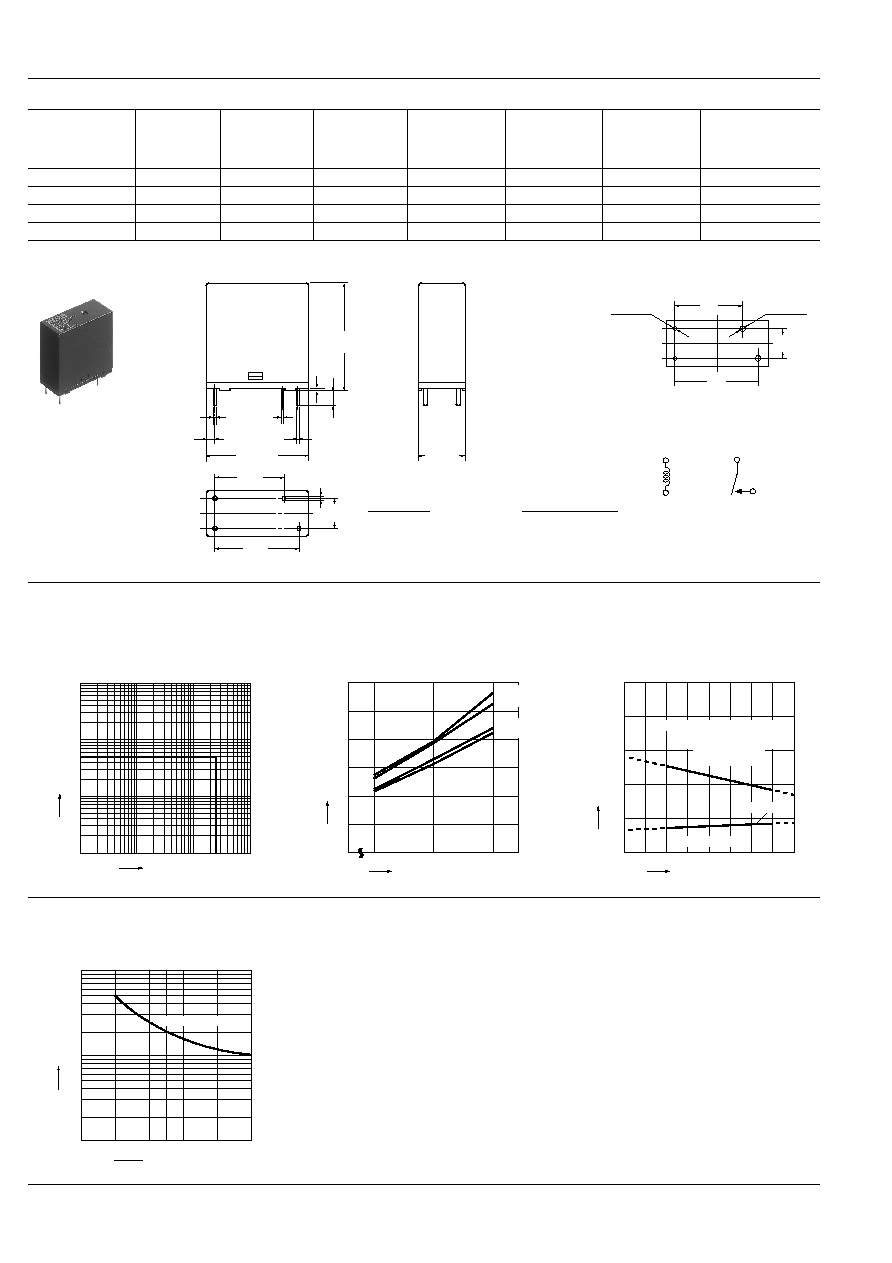
DIMENSIONS
mm
inch
4
.157
0.5
.020
1.65
.065
Max. 25.0
.984
Max. 11.0
.433
0.3
.012
0.5 dia.
.020 dia.
20.0
.787
16.5
.650
0.4
.016
Max. 24.0
.945
7.5
.295
1.0
.039
Dimension:
General tolerance
Max. 1mm
.039 inch
:
±
0.1
±
.004
1 to 3mm
.039 to .118 inch
:
±
0.2
±
.008
Min. 3mm
.118 inch
:
±
0.3
±
.012
PC board pattern (Bottom view)
Tolerance:
±
0.1
±
.004
Schematic (Bottom view)
2-0.9 dia
2-.035 dia
2-1.3 dia
2-.051 dia
16.5
.650
7.5
.295
20.0
.787
REFERENCE DATA
1. Max. switching power (AC resistive load)
2. Coil temperature rise
Sample: LKS1aF-12V, 6 pcs.
Point measured: coil inside
Contact current: 0 A, 5A
3. Ambient temperature characteristics and coil
applied voltage
Contact current: 5 A
100
10
1
5
0
10
100
Contact voltage, V
Contact current, A
80
0
0
5
10
15
20
25
30
100
120
20
∞
C 5A
20
∞
C 0A
70
∞
C 5A
70
∞
C 0A
Temperature rise,
∞
C
Coil applied voltage, %V
0
500
400
300
200
100
0
10
20
30
40
50
60
70
80
Ambient temperature,
∞
C
Allowable ambient temperatures
against % coil voltages
(max. inside the coil tem-
perature set as
115
∞
C
239
∞
F
)
Pick-up voltage
Cold start
Coil applied voltage, %V
4. Life curve
Operation frequency: 20 times/min.
(ON/OFF = 1.5s: 1.5s)
Ambient temperature: Room temperature
1
2
3
4
5
250V AC resistive load
100
10
1
0
Contact current, A
Life,
◊
10
4
LK-S
55
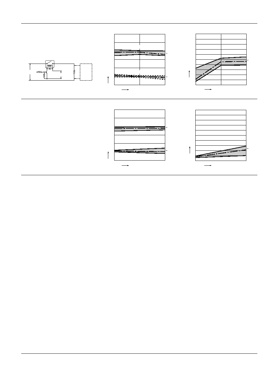
5-(1). Electrical life test
(5 A 277 V AC, resistive load)
Sample: LKS1aF-12V, 6 pcs.
Operation frequency: 20 times/min.
(ON/OFF = 1.5s: 1.5s)
Ambient temperature: 20
∞
C
68
∞
F
Circuit:
Change of pick-up and drop-out voltage
Change of contact resistance
12V DC
Contact
welding
detection
and Mis-
contacting
detection
circuit
277V AC
0
0
2
4
6
8
10
12
5
10
Max.
Min.
x
Max.
Min.
x
No. of operations,
◊
10
4
Pick-up and drop-out voltage, V
Pick-up voltage
Drop-out voltage
0
0
5
10
15
20
25
30
35
40
45
50
10
5
Max.
Min.
x
No. of operations,
◊
10
4
Contact resistance, m
5-(2). Electrical life test (UL lamp load test TV-5)
Tested sample: LKS1aF-12V, 6 pcs.
∑ Overload test
Load: 7.5 A 120 V AC (60 Hz),
Inrush: 111 A
Operation frequency: 10 times/min
(ON: OFF = 1 s: 5 s)
No. of operations: 50 ope.
∑ Endurance test
Load: 5A 120 V AC (60 Hz),
Inrush: 78 A
Operation frequency: 10 times/min
(ON: OFF = 1 s: 5 s)
No. of operations: 25,000 ope.
Change of pick-up and drop-out voltage
Change of contact resistance
0
2.5
0
2
4
6
8
10
12
Max.
Min.
x
Max.
Min.
x
No. of operations,
◊
10
4
Pick-up and drop-out voltage, V
Pick-up voltage
Drop-out voltage
0
0
5
10
15
20
25
30
35
40
45
50
2.5
Max.
Min.
x
No. of operations,
◊
10
4
Contact resistance, m
For Cautions for Use, see Relay Technical Information (Page 11 to 39).