Document Outline
- ˛ˇ
- ˛ˇ
- ˛ˇ
- ˛ˇ
- ˛ˇ
- ˛ˇ
- ˛ˇ
- ˛ˇ
- ˛ˇ
- ˛ˇ
- ˛ˇ
223
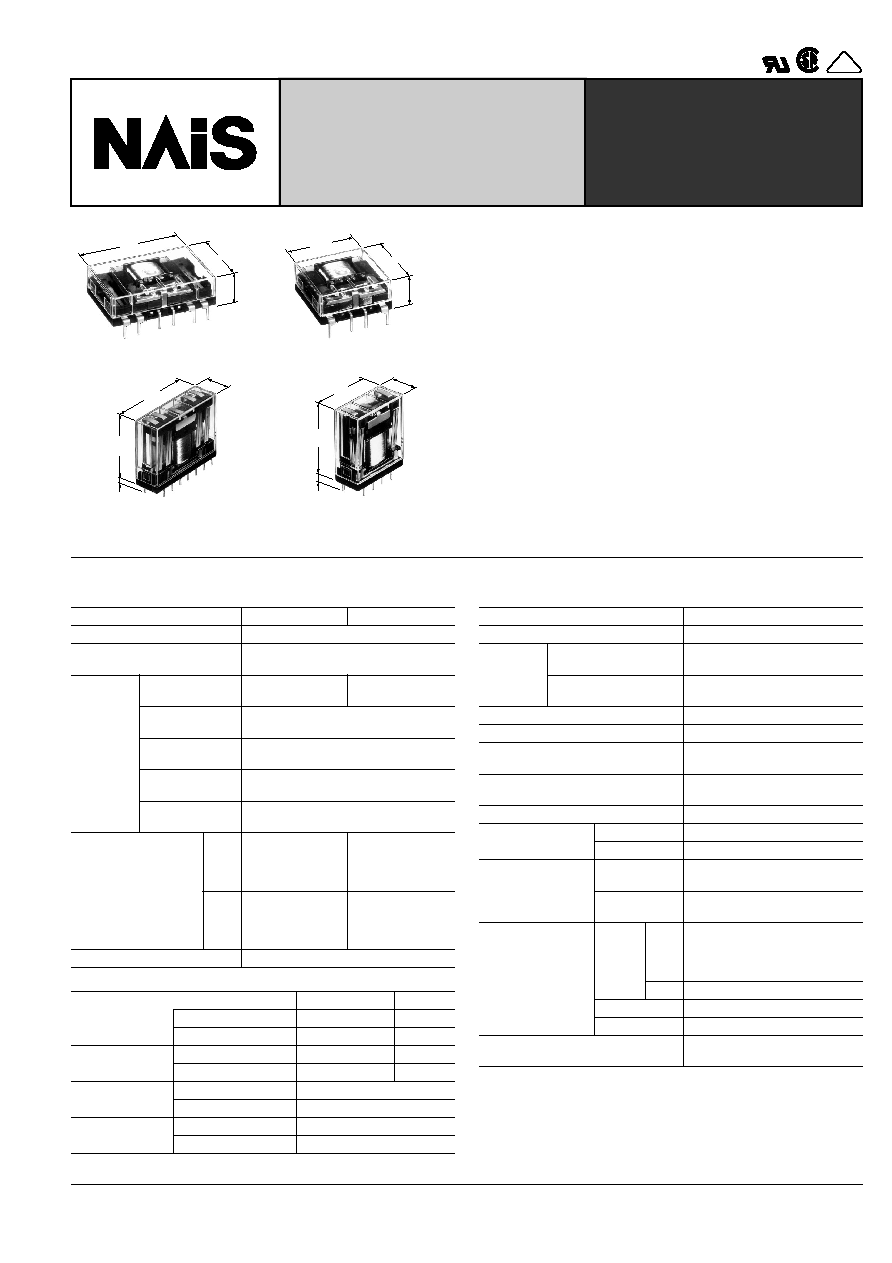
NC-RELAYS
FLAT/VERTICAL TYPE
HIGH POWER BIFURCATED
CONTACT
VDE
4C Flat type
2C Flat type
25.4
1.000
10.9
.429
38.1
1.500
25.4
1.000
10.9
.429
25.4
1.000
4C Vertical type (PC board)
2C Vertical type (PC board)
mm
inch
27.8
1.094
38.1
1.500
4.1
.161
11.2
.441
27.8
1.094
25.4
1.000
4.1
.161
11.2
.441
FEATURES
∑ Space saver -- Flat series and vertical series
∑ High contact reliability due to bifurcated contacts
-- 2C: 5 A 250 V AC, 4C: 5 A 125 V AC, 4 A 250 V AC
∑ Latching types available
∑ Low operating power
-- 2C: 200 mW, 4C: 400 mW (Single side stable)
∑ Soldering flux inflow prevented by terminal location
∑ Amber sealed types available
∑ High breakdown voltage for transient protection
-- 1,000 Vrms between open contacts, contact sets
SPECIFICATIONS
Contacts
Coil (Polarized) (at 25
∞
C
77
∞
F
)
Characteristics (at 25
∞
C
77
∞
F
50% Relative humidity)
Remarks
* Specifications will vary with foreign standards certification ratings.
*
1
Detection current: 10 mA
*
2
Half-wave pulse of sine wave: 11ms; detection time: 10
µ
s
*
3
Half-wave pulse of sine wave: 6ms
*
4
Detection time: 10
µ
s
*
5
Refer to 5. Conditions for operation, transport and storage mentioned in
AMBIENT ENVIRONMENT (Page 61).
Types
Standard
Amber sealed
Arrangement
2 Form C, 4 Form C
Initial contact resistance, max.
(By voltage drop 6 V DC 1 A)
50 m
Rating
(resistive
load)
Max. switching
power
2C: 1,250 VA 150 W
4C: 1,000 VA 150 W
2C: 750 VA 150 W
4C: 500 VA 150 W
Max. switching
voltage
250 V AC
Max. switching
current
5 A
Max. switching
carrying current
5 A
Min. switching
power
100
µ
A 1 V DC
Expected life
(minimum)
2C
10
5
at
5 A 250 V AC
5
◊
10
5
at
5 A 30 V DC
10
5
at
3 A 250 V AC
5
◊
10
5
at
5 A 30 V DC
4C
10
5
at
4 A 250 V AC
5
◊
10
5
at
5 A 30 V DC
10
5
at
2 A 250 V AC
5
◊
10
5
at
5 A 30 V DC
Contact material
Gold-clad silver nickel
Minimum
operating power
Up to 48 V DC
110 V DC
2 C single side stable Approx. 200 mW
500 mW
4 C single side stable Approx. 400 mW
500 mW
Nominal
operating power
2 C single side stable Approx. 360 mW
900 mW
4 C single side stable Approx. 720 mW
900 mW
Minimum set and
reset power
2 C 2 coil latching
Approx. 450 mW
4 C 2 coil latching
Approx. 900 mW
Nominal set and
reset power
2 C 2 coil latching
Approx. 800 mW
4 C 2 coil latching
Approx. 1,600 mW
Max. operating speed
180 cpm
Initial insulation resistance
Min. 100 M
at 500 V DC
Initial
breakdown
voltage*
1
Between open contacts,
contact sets
1,000 Vrms
Between contacts and
coil
2,000 Vrms
Operate time (at nominal voltage)
Approx. 6 ms
Release time (at nominal voltage)
Approx. 3 ms
Operate time (latching)
(at nominal voltage)
Approx. 6 ms
Reset time (latching)
(at nominal voltage)
Approx. 6 ms
Temperature rise (at nominal voltage)
Max. 65
∞
C
Shock resistance
Functional*
2
Min. 98 m/s
2
{10 G}
Destructive*
3
Min. 980 m/s
2
{100 G}
Vibration
resistance
Functional*
4
58.8 m/s
2
{6 G}, 10 to 55 Hz
at double amplitude of 1 mm
Destructive
117.6 m/s
2
{12 G}, 10 to 55 Hz
at double amplitude of 2 mm
Conditions for oper-
ation, transport and
storage*
5
(Not freezing and
condensing at low
temperature)
(Single
side
stable)
2 C
up to 48 V DC: ≠40
∞
C to +70
∞
C
≠40
∞
F to +158
∞
F
110 V DC: ≠40
∞
C to +55
∞
C
≠40
∞
F to +131
∞
F
4 C
≠40
∞
C to +55
∞
C
≠40
∞
F to +131
∞
F
(2 coil latching)
≠40
∞
C to +55
∞
C
≠40
∞
F to +131
∞
F
Humidity
5 to 85% R.H.
Unit weight
2C/Approx. 16 g
.56 oz
4C/Approx. 18 g
.63 oz
NC
224
TYPICAL APPLICATIONS
Use NC Relays for power control up to 5 A or --
Tape recorders, temperature controls, video tape recorders
Telecommunications equipment, measuring controls, copiers
Date processing equipment, computer peripherals
Automatic vendors, copiers, automatic storage controls, N.C. machines
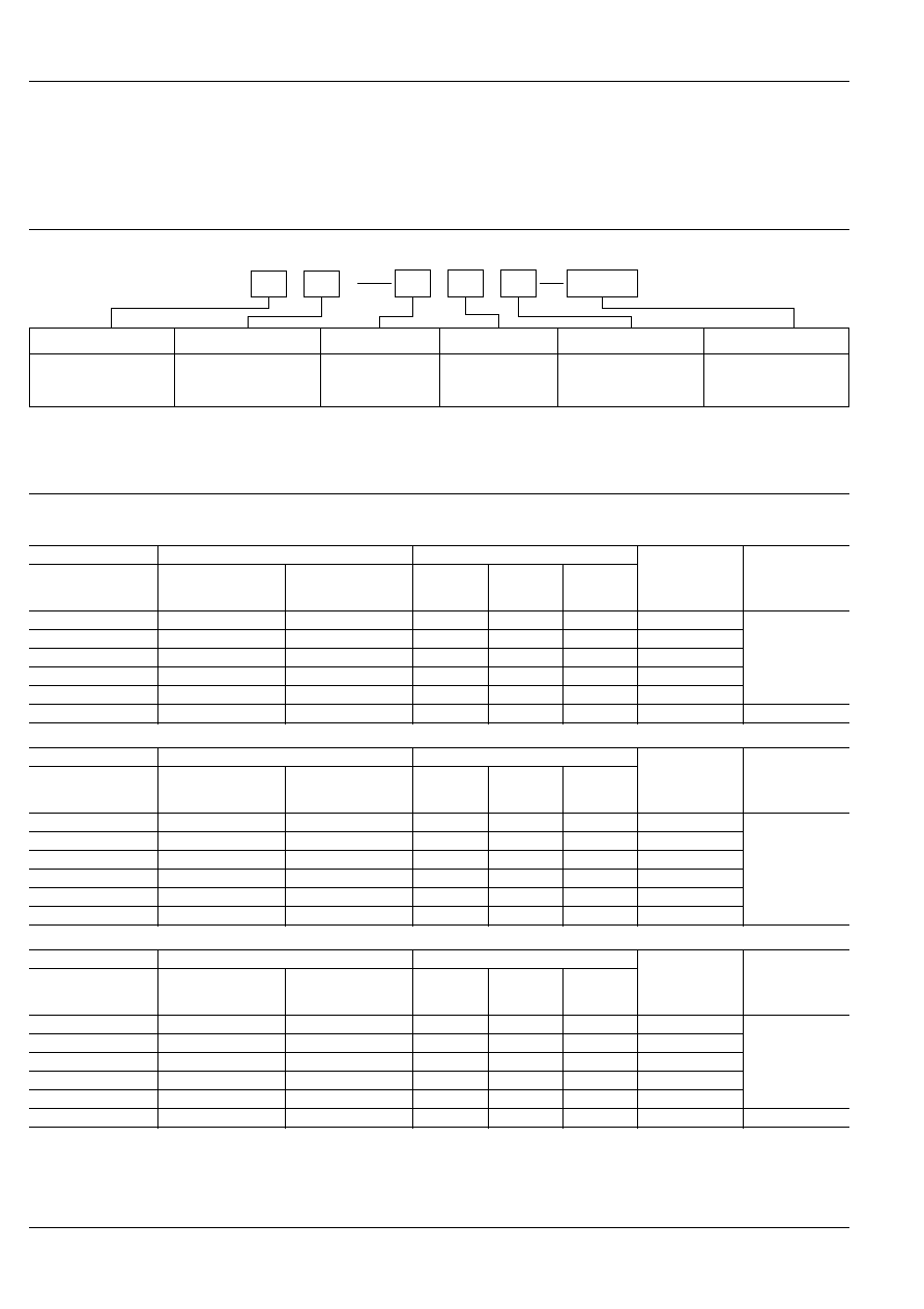
ORDERING INFORMATION
2
J
EB
P
L2
DC 12V
NC
D
Ex.
Contact arrangement
(Notes) 1. Flat series are available in PC board terminal types only.
2. For VDE recognized type, add suffix VDE.
3. Standard packing Carton: 20 pcs. Case: 200 pcs.
4. UL/CSA, approved type is standard.
2: 2 Form C
4: 4 Form C
Type classification
Coil voltage
DC 5, 6, 12, 24, 48,
110 V
Operating function
Nil: Single side stable
L2: 2 coil latching
Mounting method
Nil: Plug-in
P: PC board
termial
Housing
Nil: Vertical
series
J: Flat series
Nil: Standard type
EB: Amber sealed type
TYPE AND COIL DATA (at 20
∞
C
68
∞
F
)
(Coil data for Amber sealed types are same as those for standard types.)
2 Form C Single side stable
2 Form C 2 coil latching
4 Form C Single side stable
Flat series
Vertical series
Coil voltage, V DC
Coil resistance,
(
±
10%)
Nominal
operating power,
mW
PC board terminal
Plug-in
PC board terminal
Pick-up
voltage
(max.)
Drop-out
voltage
(min.)
Maximum
allowable
voltage
NC2D-JP-DC5V
NC2D-DC5V
NC2D-P-DC5V
4.0
0.5
6.75
69.4
360
NC2D-JP-DC6V
NC2D-DC6V
NC2D-P-DC6V
4.8
0.6
8.1
100
NC2D-JP-DC12V
NC2D-DC12V
NC2D-P-DC12V
9.6
1.2
16.2
400
NC2D-JP-DC24V
NC2D-DC24V
NC2D-P-DC24V
19.2
2.4
32.4
1,600
NC2D-JP-DC48V
NC2D-DC48V
NC2D-P-DC48V
38.4
4.8
64.8
6,400
NC2D-JP-DC110V
NC2D-DC110V
NC2D-P-DC110V
88.0
11.0
121
13,500
900
Flat series
Vertical series
Coil voltage, V DC
Coil resistance,
(
±
10%)
Nominal
operating power,
mW
PC board terminal
Plug-in
PC board terminal
Pick-up
voltage
(max.)
Reset
voltage
(max.)
Maximum
allowable
voltage
NC2D-JPL2-DC5V
NC2D-L2-DC5V
NC2D-PL2-DC5V
4.0
4.0
5.5
31.3
800
NC2D-JPL2-DC6V
NC2D-L2-DC6V
NC2D-PL2-DC6V
4.8
4.8
6.6
45.0
NC2D-JPL2-DC12V
NC2D-L2-DC12V
NC2D-PL2-DC12V
9.6
9.6
13.2
180
NC2D-JPL2-DC24V
NC2D-L2-DC24V
NC2D-PL2-DC24V
19.2
19.2
26.4
720
NC2D-JPL2-DC48V
NC2D-L2-DC48V
NC2D-PL2-DC48V
38.4
38.4
52.8
2,880
NC2D-JPL2-DC110V NC2D-L2-DC110V
NC2D-PL2-DC110V
88.0
88.0
121
15,125
Flat series
Vertical series
Coil voltage, V DC
Coil resistance,
(
±
10%)
Nominal
operating power,
mW
PC board terminal
Plug-in
PC board terminal
Pick-up
voltage
(max.)
Drop-out
voltage
(min.)
Maximum
allowable
voltage
NC4D-JP-DC5V
NC4D-DC5V
NC4D-P-DC5V
4.0
0.5
5.5
34.7
720
NC4D-JP-DC6V
NC4D-DC6V
NC4D-P-DC6V
4.8
0.6
6.6
50
NC4D-JP-DC12V
NC4D-DC12V
NC4D-P-DC12V
9.6
1.2
13.2
200
NC4D-JP-DC24V
NC4D-DC24V
NC4D-P-DC24V
19.2
2.4
26.4
800
NC4D-JP-DC48V
NC4D-DC48V
NC4D-P-DC48V
38.4
4.8
52.8
3,200
NC4D-JP-DC110V
NC4D-DC110V
NC4D-P-DC110V
88.0
11.0
121
13,500
900
NC
225
4 Form C 2 coil latching
Flat series
Vertical series
Coil voltage, V DC
Coil resistance,
(
±
10%)
Nominal
operating power,
mW
PC board terminal
Plug-in
PC board terminal
Pick-up
voltage
(max.)
Reset
voltage
(max.)
Maximum
allowable
voltage
(within 2 min.)
NC4D-JPL2-DC5V
NC4D-L2-DC5V
NC4D-PL2-DC5V
4.0
4.0
5.5
15.6
1,600
NC4D-JPL2-DC6V
NC4D-L2-DC6V
NC4D-PL2-DC6V
4.8
4.8
6.6
22.5
NC4D-JPL2-DC12V
NC4D-L2-DC12V
NC4D-PL2-DC12V
9.6
9.6
13.2
90
NC4D-JPL2-DC24V
NC4D-L2-DC24V
NC4D-PL2-DC24V
19.2
19.2
26.4
360
NC4D-JPL2-DC48V
NC4D-L2-DC48V
NC4D-PL2-DC48V
38.4
38.4
52.8
1,440
NC4D-JPL2-DC110V NC4D-L2-DC110V
NC4D-PL2-DC110V
88.0
88.0
121
7,560
Notes:
1. Two coil latching relay 4C series are for intermittent operation only. Power should
be applied to coil continuously for no more than two minutes.
2. Coil resistance is the measured value at a coil temperature of 20
∞
C. Compensate
coil resistance by plus or minus 0.4% for each degree (
∞
C) of coil temperature
change.
3. "Maximum allowable voltage" is that value at maximum contact rating and maxi-
mum ambient temperature. The graph shown in the data describes the inter-rela-
tionship; care should be taken to prevent the total of ambient temperature and the
coil temperature rise from exceeding 120
∞
C.
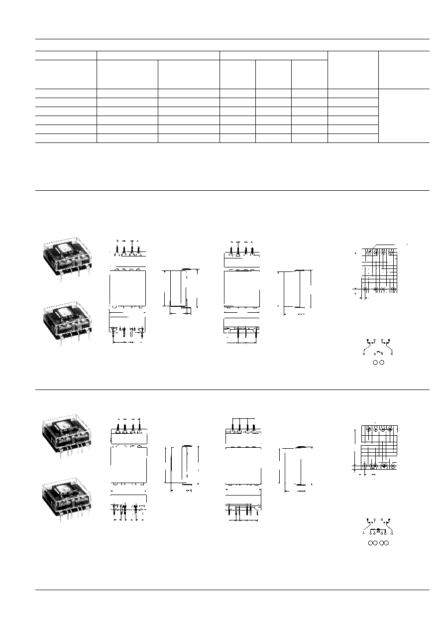
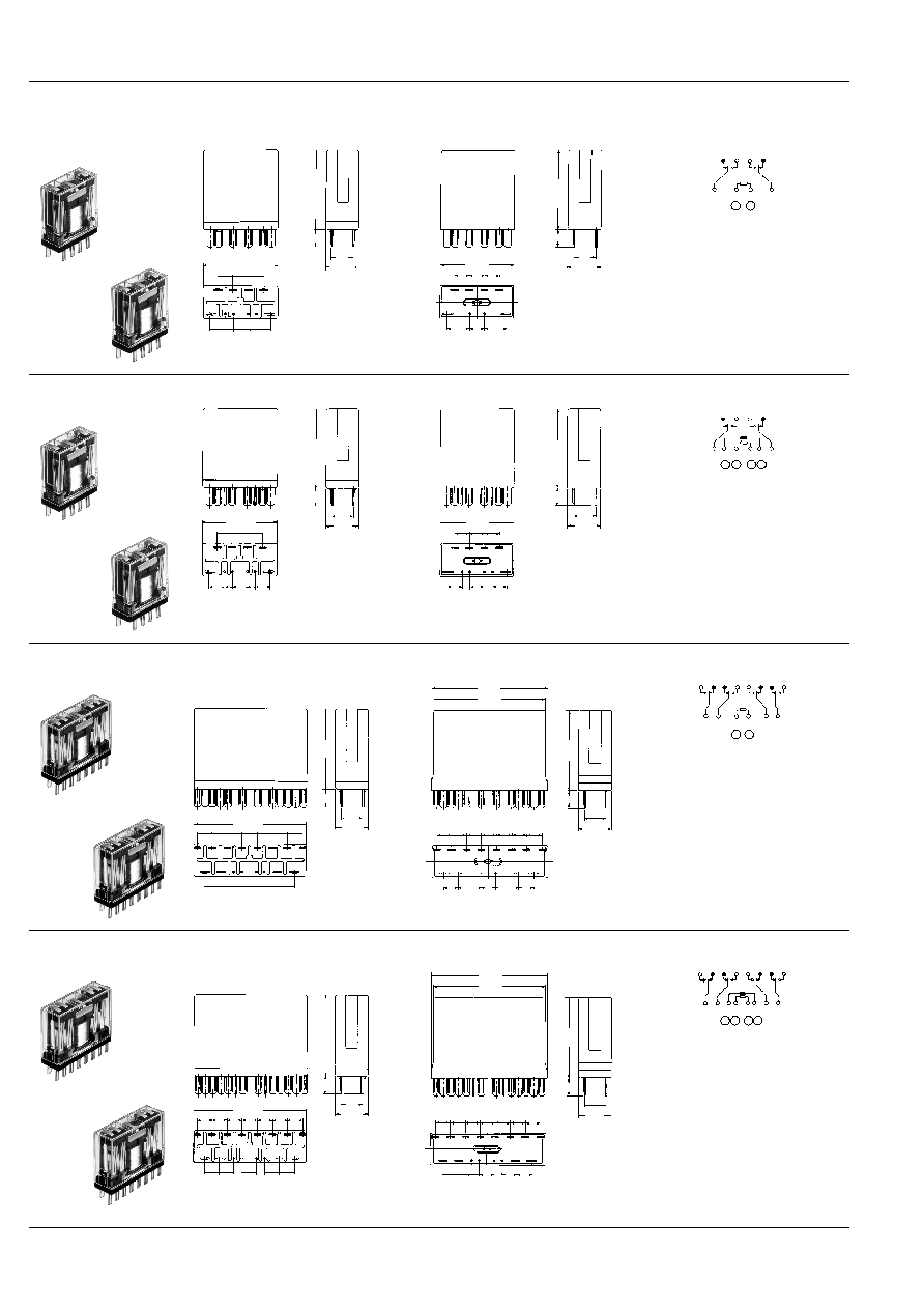
DIMENSIONS
Flat series
2C single side stable
(NC2D-JP)
(NC2ED-JP)
Standard type
Amber sealed type
General tolerance:
±
0.5
±
.020
25.4
1.000
10.9
.429
3.5
.138
25.4
1.000
7.62
.300
5.08
.200
7.62
.300
27.94
1.100
5.08
.200
5.08
.200
5.08
.200
25.4
1.000
25.4
1.000
27.94
1.100
10.9
.429
3.5
.138
7.62
.300
5.08
.200
7.62
.300
5.08
.200
5.08
.200
5.08
.200
PC board pattern (Copper-side view)
Tolerance:
±
0.1
±
.004
Schematic (Top view)
Deenergized position
8-1.2 DIA. HOLES
8-.047 DIA. HOLES
27.94
1.100
2.54
.100
2.54
.100
7 5
4 2
11
12 13 14
+
≠
14 13 12
4
2
5
7
11
mm
inch
2C 2 coil latching
(NC2D-JPL2)
(NC2ED-JPL2)
Standard type
Amber sealed type
General tolerance:
±
0.5
±
.020
25.4
1.000
10.9
.429
3.5
.138
25.4
1.000
2.54
.100
2.54
.100
5.08
.200
5.08
.200
5.08
.200
27.94
1.100
5.08
.200
5.08
.200
5.08
.200
25.4
1.000
25.4
1.000
27.94
1.100
10.9
.429
3.5
.138
2.54
.100
2.54
.100
5.08
.200
5.08
.200
5.08
.200
5.08
.200
5.08
.200
5.08
.200
PC board pattern (Copper-side view)
Tolerance:
±
0.1
±
.004
Schematic (Top view)
Diagram shows the "reset" position
when terminals 3 and 6 are energized.
Energize terminals 4 and 5 to transfer
contacts.
10-1.2 DIA. HOLES
10-.047 DIA. HOLES
27.94
1.100
2.54
.100
2.54
.100
0.5
.020
7 5
4 2
11
12 13 14
14 13 12
4
2 3
4
5 7
11
+
+
≠ ≠

NC
226
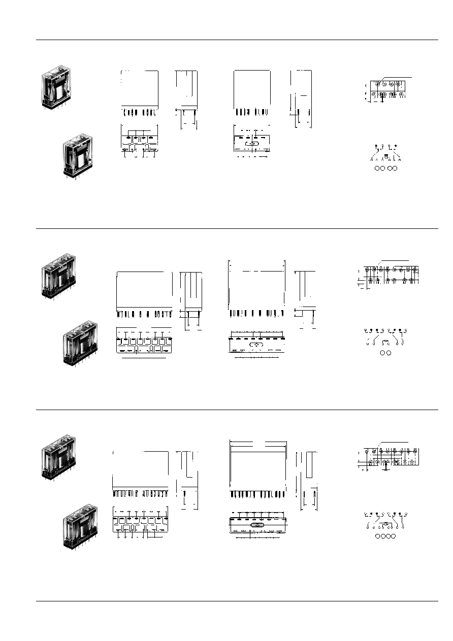
4C single side stable
(NC4D-JP)
(NC4ED-JP)
Standard type
Amber sealed type
General tolerance:
±
0.5
±
.020
25.4
1.000
10.9
.429
3.5
.138
38.1
1.500
5.08
.200
5.08
.200
5.08
.200
7.62
.300
7.62
.300
27.94
1.100
5.08
.200
5.08
.200
5.08
.200
5.08
.200
5.08
.200
5.08
.200
5.08
.200
38.1
1.500
25.4
1.000
27.94
1.100
10.9
.429
3.5
.138
5.08
.200
5.08
.200
5.08
.200
7.62
.300
7.62
.300
5.08
.200
5.08
.200
5.08
.200
5.08
.200
5.08
.200
5.08
.200
5.08
.200
PC board pattern (Copper-side view)
Tolerance:
±
0.1
±
.004
Schematic (Top view)
Deenergized position
14-1.2 DIA. HOLES
14-.047 DIA. HOLES
27.94
1.100
2.54
.100
2.54
.100
7 5
4 2
1
8
10 11 12 13 14 15 16
9
16 15 14 13 12 11 10 9
4
1 2
7
5 8
+
≠
mm
inch
4C 2 coil latching
(NC4D-JPL2)
(NC4ED-JPL2)
Standard type
Amber sealed type
General tolerance:
±
0.5
±
.020
25.4
1.000
10.9
.429
3.5
.138
38.1
1.500
5.08
.200
5.08
.200
5.08
.200
5.08
.200
5.08
.200
2.54
.100
2.54
.100
5.08
.200
5.08
.200
5.08
.200
5.08
.200
5.08
.200
5.08
.200
5.08
.200
27.94
1.100
38.1
1.500
25.4
1.000
27.94
1.100
10.9
.429
3.5
.138
5.08
.200
5.08
.200
5.08
.200
5.08
.200
5.08
.200
2.54
.100
2.54
.100
5.08
.200
5.08
.200
5.08
.200
5.08
.200
5.08
.200
5.08
.200
5.08
.200
PC board pattern (Copper-side view)
Tolerance:
±
0.1
±
.004
Schematic (Top view)
Diagram shows the "reset" position
when terminals 3 and 6 are energized.
Energize terminals 4 and 5 to transfer
contacts.
16-1.2 DIA. HOLES
16-.047 DIA. HOLES
2.54
.100
2.54
.100
0.5
.020
7 5
6 3
4 2
1
8
10
12
11 13 15
14 16
9
27.94
1.100
16 15 14 13 12 11 10 9
4
3
1 2
7
5 6
8
+
+
≠ ≠
Slim series
PC board series
2C single side stable
(NC2D-P)
(NC2ED-PL2)
Standard type
Amber sealed type
General tolerance:
±
0.5
±
.020
7.62
.300
11.2
.441
25.4
1.000
5.08
.200
7.62
.300
7.62
.300
5.08
.200
5.08
.200
5.08
.200
11
12
13
14
2
3
5
4
6
7
27.8
1.094
4.1
.161
25.4
1.000
11.2
.441
4.1
.161
5.08
.200
5.08
.200
7.62
.300
7.62
.300
7.62
.300
5.08
.200
5.08
.200
27.8
1.094
PC board pattern (Copper-side view)
Tolerance:
±
0.1
±
.004
Schematic (Bottom view)
Deenergized position
8-1.2 DIA. HOLES
8-.047 DIA. HOLES
2.54
.100
2.54
.100
7 5
4 2
12
11 13
14
7.62
.300
+ ≠
11 12 13 14
5 2
7
4
NC
227
2C 2 coil latching
(NC2D-PL2)
(NC2ED-P)
Standard type
Amber sealed type
General tolerance:
±
0.5
±
.020
7.62
.300
11.2
.441
5.08
.200
5.08
.200
2.54
.100
7.62
.300
4.1
.161
5.08
.200
5.08
.200
5.08
.200
27.8
1.094
25.4
1.000
11
12
13
14
2
3
4
5
6
7
25.4
1.000
11.2
.441
4.1
.161
5.08
.200
5.08
.200
2.54
.100
2.54
.100
5.08
.200
7.62
.300
5.08
.200
5.08
.200
5.08
.200
27.8
1.094
PC board pattern (Copper-side view)
Tolerance:
±
0.1
±
.004
Schematic (Bottom view)
Diagram shows the "reset" position
when terminals 3 and 6 are energized.
Energize terminals 4 and 5 to transfer
contacts.
10-1.2 DIA. HOLES
10-.047 DIA. HOLES
2.54
.100
2.54
.100
0.5
.020
7
11 12
13 14
6 3
5 4
2
7.62
.300
11 12 13 14
5
6 3
2
7
4
+
+
≠ ≠
mm
inch
4C single side stable
(NC4D-P)
(NC4ED-P)
Standard type
Amber sealed type
General tolerance:
±
0.5
±
.020
7.62
.300
11.2
.441
7.62
.300
7.62
.300
4.1
.161
5.08
.200
5.08
.200
5.08
.200
5.08
.200
5.08
.200
5.08
.200
5.08
.200
5.08
.200
5.08
.200
5.08
.200
27.8
1.094
38.1
1.500
11
12
13
14
15
16
10
9
8
7
6 5
4 3
2
1
11.2
.441
4.1
.161
7.62
.300
7.62
.300
5.08
.200
5.08
.200
5.08
.200
7.62
.300
5.08
.200
5.08
.200
5.08
.200
5.08
.200
5.08
.200
5.08
.200
5.08
.200
38.1
1.500
38.9
1.520
27.8
1.094
PC board pattern (Copper-side view)
Tolerance:
±
0.1
±
.004
Schematic (Bottom view)
Deenergized position
14-1.2 DIA. HOLES
14-.047 DIA. HOLES
2.54
.100
2.54
.100
8
7
1
2
4
5
9
10
15 16
14
13
12
11
7.62
.300
9 10 11 12 13 14 15 16
5
7 2
1
8
4
+ ≠
4C 2 coil latching
(NC4D-PL2)
(NC4ED-PL2)
Standard type
Amber sealed type
General tolerance:
±
0.5
±
.020
7.62
.300
11.2
.441
2.54
.100
2.54
.100
4.1
.161
5.08
.200
5.08
.200
5.08
.200
5.08
.200
5.08
.200
5.08
.200
5.08
.200
5.08
.200
5.08
.200
5.08
.200
5.08
.200
5.08
.200
38.1
1.500
11
12
13
14
15
16
10
9
8
7
6 5
4 3
2
1
27.8
1.094
11.2
.441
4.1
.161
2.54
.100
2.54
.100
5.08
.200
5.08
.200
5.08
.200
5.08
.200
5.08
.200
7.62
.300
5.08
.200
5.08
.200
5.08
.200
5.08
.200
5.08
.200
5.08
.200
5.08
.200
38.1
1.500
38.9
1.520
27.8
1.094
PC board pattern (Copper-side view)
Tolerance:
±
0.1
±
.004
Schematic (Bottom view)
Diagram shows the "reset" position
when terminals 3 and 6 are energized.
Energize terminals 4 and 5 to transfer
contacts.
16-1.2 DIA. HOLES
16-.047 DIA. HOLES
2.54
.100
2.54
.100
0.5
.020
8
7
1
2
4 3
5
6
9
10
15 16
14
13
12
11
7.62
.300
9 10 11 12 13 14 15 16
5
7 2
1
8
4
6 3
+
+
≠ ≠
NC
228
Slim series
Plug-in series
2C single side stable
(NC2D)
(NC2ED)
Standard type
Amber sealed type
General tolerance:
±
0.5
±
.020
7.62
.300
11.2
.441
6.1
.240
5.08
.200
5.08
.200
5.08
.200
5.08
.200
27.8
1.094
7.62
.300
7.62
.300
13
14
12
11
7
6 5
4 3
2
25.4
1.000
11.2
.441
6.1
.240
7.62
.300
7.62
.300
5.08
.200
5.08
.200
5.08
.200
5.08
.200
7.62
.300
27.8
1.094
25.4
1.000
Schematic (Bottom view)
Deenergized position
+ ≠
11 12 13 14
5 2
7
4
mm
inch
2C 2 coil latching
(NC2D-L2)
(NC2ED-L2)
Standard type
Amber sealed type
General tolerance:
±
0.5
±
.020
7.62
.300
11.2
.441
6.1
.240
5.08
.200
5.08
.200
5.08
.200
27.8
1.094
13
14
12
11
7
6 5
4 3
2
25.4
1.000
2.54
.100
2.54
.100
5.08
.200
5.08
.200
5.08
.200
11.2
.441
6.1
.240
5.08
.200
5.08
.200
5.08
.200
7.62
.300
27.8
1.094
25.4
1.000
2.54
.100
2.54
.100
5.08
.200
5.08
.200
5.08
.200
Schematic (Bottom view)
Diagram shows the "reset" position
when terminals 3 and 6 are energized.
Energize terminals 4 and 5 to transfer
contacts.
11 12 13 14
5
6 3
2
7
4
+
+
≠ ≠
4C single side stable
(NC4D)
(NC4ED-L2)
Standard type
Amber sealed type
General tolerance:
±
0.5
±
.020
7.62
.300
6.1
.240
5.08
.200
5.08
.200
5.08
.200
5.08
.200
5.08
.200
5.08
.200
5.08
.200
27.8
1.094
13
14
15
16
12
11
10
9
7
6
8
5
4 3
2
1
38.1
1.500
5.08
.200
5.08
.200
7.62
.300
7.62
.300
5.08
.200
11.2
.441
11.2
.441
6.1
.240
5.08
.200
5.08
.200
5.08
.200
5.08
.200
5.08
.200
5.08
.200
5.08
.200
7.62
.300
38.9
1.520
27.8
1.094
38.1
1.500
5.08
.200
5.08
.200
7.62
.300
7.62
.300
5.08
.200
Schematic (Bottom view)
Deenergized position
9 10 11 12 13 14 15 16
5
7 2
1
8
4
+ ≠
4C 2 coil latching
(NC4D-L2)
(NC4ED-L2)
Standard type
Amber sealed type
General tolerance:
±
0.5
±
.020
7.62
.300
6.1
.240
5.08
.200
5.08
.200
5.08
.200
5.08
.200
5.08
.200
5.08
.200
5.08
.200
27.8
1.094
13
14
15
16
12
11
10
9
7
6
8
5
4 3
2
1
38.1
1.500
11.2
.441
2.54
.100
2.54
.100
5.08
.200
5.08
.200
5.08
.200
5.08
.200
5.08
.200
11.2
.441
6.1
.240
5.08
.200
5.08
.200
5.08
.200
5.08
.200
5.08
.200
5.08
.200
5.08
.200
7.62
.300
38.9
1.520
27.8
1.094
38.1
1.500
2.54
.100
2.54
.100
5.08
.200
5.08
.200
5.08
.200
5.08
.200
5.08
.200
Schematic (Bottom view)
Diagram shows the "reset" position
when terminals 3 and 6 are energized.
Energize terminals 4 and 5 to transfer
contacts.
9 10 11 12 13 14 15 16
5
6
8 7
2
4 3
1
+
+
≠ ≠
NC
229
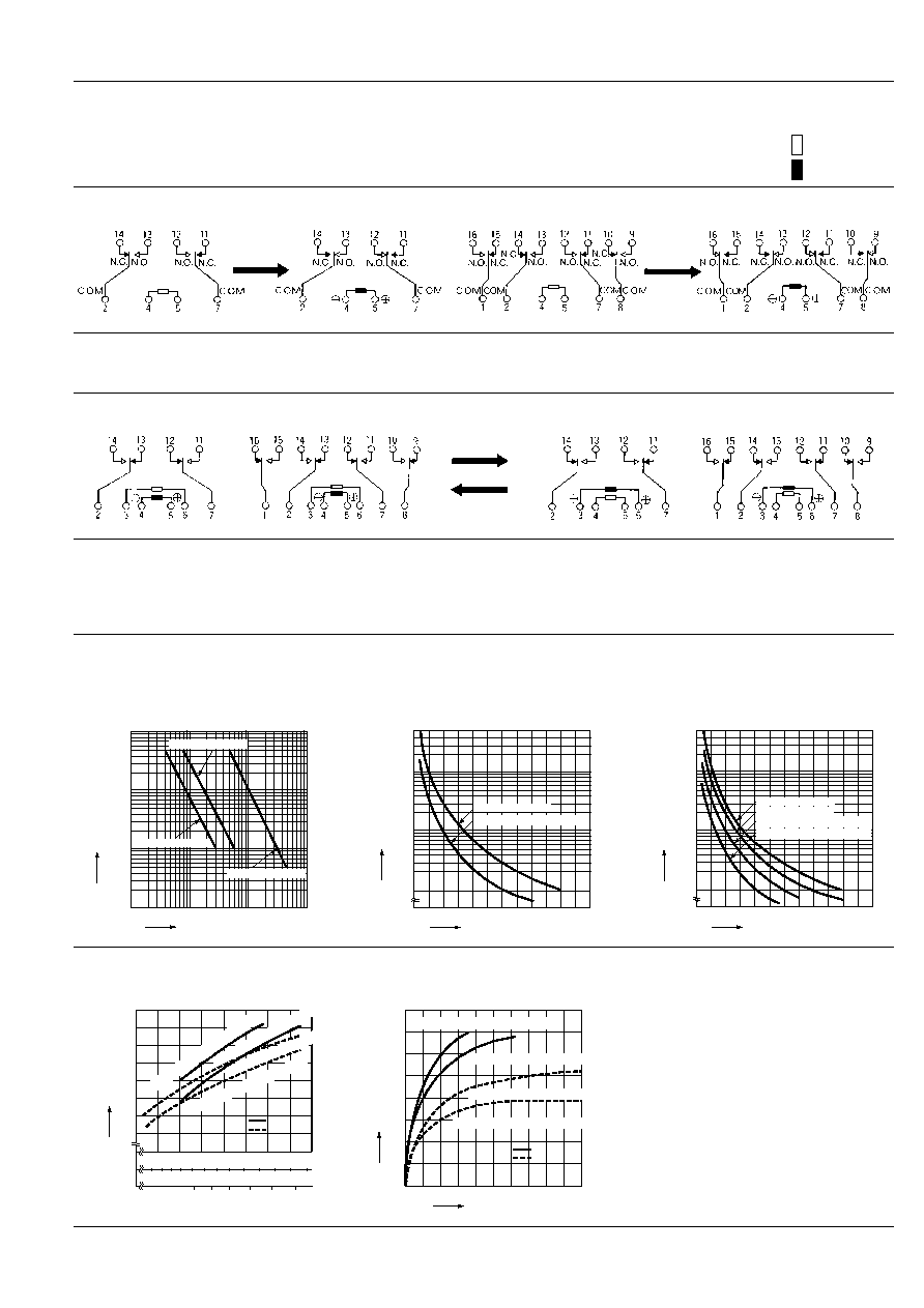
Schematic
-- Energize relays only in the polarities shown --
1. Single side stable
Same operation as conventional magnetic relays.
Contacts will transfer only when coil is energized under indicated polarity.
2. 2 coil latching
Contacts will transfer only when coil is energized under indicated polarity.
Once transferred, contacts remain in that position even with power off until opposite coil is energized at indicated polarity.
2C
4C
2C
4C
2C
4C
Reset
Reset
set
set
set
set
Reset
Reset
Diagrams show the "set" position when
terminals 4 (≠) and 5 (+) are energized.
When the coil current is switched off,
these contacts remain in "make" position.
Energize terminals 3 (≠) and 6 (+) to
transfer the contacts.
Diagrams show the "reset" position when
terminals 3 (≠) and 6 (+) are energized.
Energize terminals 4 (≠) and 5 (+) to
transfer the contacts.
REFERENCE DATA
Standard type
1.-(1) Life curve
DC load (2C, 4C)
AC load (2C)
AC load (4C)
Contact carrying current, A
Expected life,
◊
10
4
0.1
1.0
10
100
1,000
10,000
220 V DC resistive
110 V DC resistive
30 V DC resistive
Contact carrying current, A
Expected life,
◊
10
4
100
10
0
1,000
5,000
1
2
3
4
5
250 V AC resistive
250 V AC inductive (pf=0.4)
Contact carrying current, A
Expected life,
◊
10
4
100
10
0
1,000
5,000
125 V AC resistive
250 V AC resistive
125 V AC inductive (pf=0.4)
250 V AC inductive (pf=0.4)
1
2
3
4
5
2.-(1) Temperature rise characteristics for sin-
gle side stable
Measured portion: Inside the coil
20
30
40
50
60
70
80
0.4
0.6
0.8
1.0
1.2
1.4
1.6 1.8W
100 120 140 160
180
200 220%V
100 110 120 130 140 150%V
5 A (Contact carring current)
3 A (Contact carring current)
4C
2C
Temperature rise,
∞
C
Operating
power
Coil voltage
2C : up to
48 V DC
2C : 100 V DC
4C : all types
)
)
(
(
5 A (Contact carring current)
3 A (Contact carring current)
2.-(2) Temperature rise characteristics for 2 coil
latching
Measured portion: Inside the coil
5
10
15
25
20
0
10
20
30
40
50
60
70
0 A (No. contact carring current)
0 A (No. contact carring current)
5 A (Max. contact carring current)
5 A (Max. contact carring current)
Energizing time, min.
Temperature rise,
∞
C
4C
2C
deenergized coil
energized coil

NC
230
3. Operate time for single side stable
4. Release time for single side stable
Coil applied voltage,%V
Operate time, ms
4
2
10
6
8
12
16
14
18
20
80
100
90
110
Min.
Max.
4c
2c
Min.
Max.
Coil applied voltage,%V
Release time, ms
5
4
3
2
1
80
100
90
110
4c
2c
Max.
Min.
Max.
Min.
5. Rate of change of pick-up and drop-out voltage
2 Form C single side stable
4 Form C single side stable
100
≠40 ≠20
0
20
40
60
80
80
90
110
120
Ambient temperature,
∞
C
Drop-out voltage
Pick-up voltage
Rated of change, %
100
≠40 ≠20
0
20
40
60
80
80
90
110
120
Ambient temperature,
∞
C
Drop-out voltage
Pick-up voltage
Rated of change, %
6.-(1) Ambient temperature vs Max. continuous
voltage
Sample: NC2D-P-DC24 V (2c slim single side stable)
6.-(2) Ambient temperature vs Max. continuous
voltage
Sample: NC2D-P-DC110 V (2c slim single side sta-
ble), NC4D-P-DC24 V (4c slim single side stable)
100
150
200
250
Ambient temperature,
∞
C
40
50
60
70
Max. continuous voltage, %V
0 A (Contact carring current)
3 A (Contact carring current)
5 A (Contact carring current)
30
40
50
100
150
200
250
Ambient temperature,
∞
C
Max. continuous voltage, %V
0 A (Contact carring current)
3 A (Contact carring current)
5 A (Contact carring current)

NC
231
ACCESSORIES
NC2 Flat
NC4 Flat
NC2 Slim
NC4 Slim
Sockets incorporate a spring clip at each
end permitting single "snap-in" attach-
ment to chassis or panels - no screws
necessary. Relays are held firmly in the
socket by clips integrally molded into the
socket.
TYPES
For Flat series
Standard packing:
Carton: 20 pieces
Case: 200 pieces
For Slim series
Part No.
Terminals
Mating relay
NC2-JPS
P/C board
NC2D-JP
NC4-JPS
P/C board
NC4D-JP
NC2-JPL2S
P/C board
NC2D-JPL2
NC4-JPL2S
P/C board
NC4D-JPL2
Part No.
Terminals
Mating relay
NC2-PS
P/C board
NC2D-P
NC4-PS
P/C board
NC4D-P
NC2-SS
Solder
NC2D
NC4-SS
Solder
NC2D
NC2-L2PS
P/C board
NC4D-PL2
NC4-L2PS
P/C board
NC2D-PL2
NC4-L2SS
Solder
NC2D-L2
NC4-L2SS
Solder
NC4D-L2
SPECIFICATIONS
Caution: Do not insert or remove relays while in the energized condition.
Maximum continuous current
Flat series: 5 A 250 V AC Slim series: 5 A 250 V AC
Initial breakdown voltage
2,000 V AC (Except for coil-coil of L2 types: 1,500 V AC)
Initial insulation resistance
100 M
at 500 V DC
Heat resistance
150
∞
C (
302
∞
F
) for one hour
NC
232
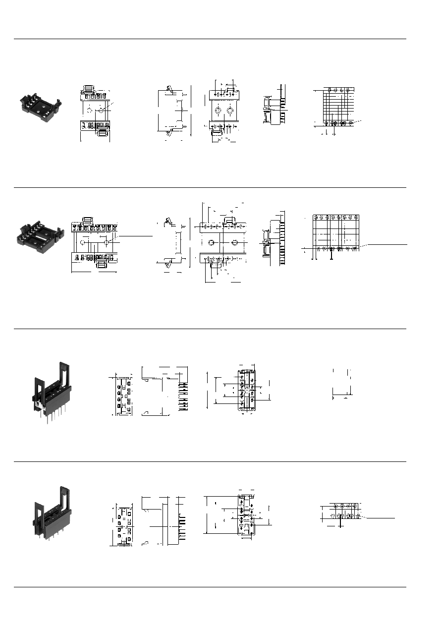
DIMENSIONS
Flat series
NC2-JPS
NC2-JPL2S
Terminals 3 and 6 excluded for NC2-JPS.
2-3.5 DIA. HOLES
2-.138 DIA. HOLES
10.16
.400
34.9
1.374
44.3
1.744
27.94
1.100
14.8
.582
25.4
1.000
15.24
.600
11 12 13 14
7 6 5
2
4 3
5.08
.200
10.16
.400
20.32
.800
5.08
.200
General tolerance:
±
0.5
±
.020
Terminal portion
3.9
.154
0.1 MAX.
.004
PC board pattern
(copper-side view)
27.94
1.100
2.54
.100
2.54
.100
0.5
.020
10-1.2 DIA. HOLES
10-.047 DIA. HOLES
11 12 13 14
2
3
4
5
6
7
Tolerance:
±
0.1
±
.004
mm
inch
NC4-JPS
NC4-JPL2S
Terminals 3 and 6 excluded for NC4-JPS.
2-3.5 DIA. HOLES
2-.138 DIA. HOLES
34.9
1.374
44.3
1.744
27.94
1.100
14.8
.582
30.48
1.200
40
1.575
15.24
.600
9 10 11 12 13 14 15 16
7
8
6 5 4 3 2
1
5.08
.200
5.08
.200
10.16
.400
20.32
.800
20.32
.800
35.56
1.400
25.4
1.000
General tolerance:
±
0.5
±
.020
Terminal portion
3.9
.154
0.1 MAX.
.004
PC board pattern
(copper-side view)
27.94
1.100
2.54
.100
2.54
.100
0.5
.020
16-1.2 DIA. HOLES
16-.047 DIA. HOLES
9 10 11
15 16
12 13 14
7
8
6 5 4 3
2
1
Tolerance:
±
0.1
±
.004
Slim series
NC2-SS
NC2-L2S
Terminal width: 1.9
.075
Terminal thickness: 0.4
.016
Terminals 3 and 6 excluded for NC2-SS.
20.4
.803
3.9
.154
1.0
.039
8.6
.339
8.0
.315
11.2
.441
15.24
.660
7.62
.300
27.9
1.100
10.16
.400
20.32
.800
5.08
.200
5.08
.200
12.6
.496
29.9
1.177
General tolerance:
±
0.5
±
.020
Chassis cutout
Chassis thickness range: 1.0 to 2.0
.039 to .079
28.4
1.118
11.5
.453
NC2-PS
NC2-L2P
Terminal width: 0.9
.035
Terminal thickness: 0.4
.016
Terminals 3 and 6 excluded for NC2-PS.
20.4
.803
8.6
.339
1.0
.039
4.6
.181
3.9
.154
29.9
1.177
12.6
.496
11.2
.441
15.24
.660
7.62
.300
27.9
1.100
10.16
.400
20.32
.800
5.08
.200
5.08
.200
General tolerance:
±
0.5
±
.020
PC board pattern
(copper-side view)
7.62
.300
2.54
.100
2.54
.100
0.5
.020
10-1.2 DIA. HOLES
10-.047 DIA. HOLES
6 5
4 3
2
11 12 13 14
7
Tolerance:
±
0.1
±
.004
Terminal width: 0.9
.035
Terminal thickness: 0.4
.016
Terminal width: 0.9
.035
Terminal thickness: 0.4
.016
NC
233
NC4-SS
NC4-L2S
Terminal width: 1.9
.075
Terminal thickness: 0.4
.016
Terminals 3 and 6 excluded for NC4-SS.
20.4
.803
3.9
.154
1.0
.039
8.6
.339
8.0
.315
11.2
.441
15.24
.600
25.4
1.000
35.56
1.400
42.0
1.654
30.48
1.200
10.16
.400
20.32
.800
5.08
.200
5.08
.200
12.6
.496
44.0
1.732
7.62
.300
General tolerance:
±
0.5
±
.020
Chassis cutout
Chassis thickness range: 1.0 to 2.0
.039 to .079
11.5
.453
42.5
1.673
NC4-PS
NC4-L2P
Terminal width: 0.9
.035
Terminal thickness: 0.4
.016
Terminals 3 and 6 excluded for NC4-PS.
20.4
.803
8.6
.339
1.0
.039
4.6
.181
3.9
.154
44.0
1.732
12.6
.496
11.2
.441
35.56
1.400
15.24
.600
25.4
1.000
7.62
.300
30.48
1.200
42.0
1.654
10.16
.400
20.32
.800
5.08
.200
5.08
.200
General tolerance:
±
0.5
±
.020
PC board pattern
(copper-side view)
7.62
.300
2.54
.100
2.54
.100
0.5
.020
16-1.2 DIA. HOLES
16-.047 DIA. HOLES
7
8
6 5 4 3 2 1
9 10 11 12 13 14 15 16
Tolerance:
±
0.1
±
.004
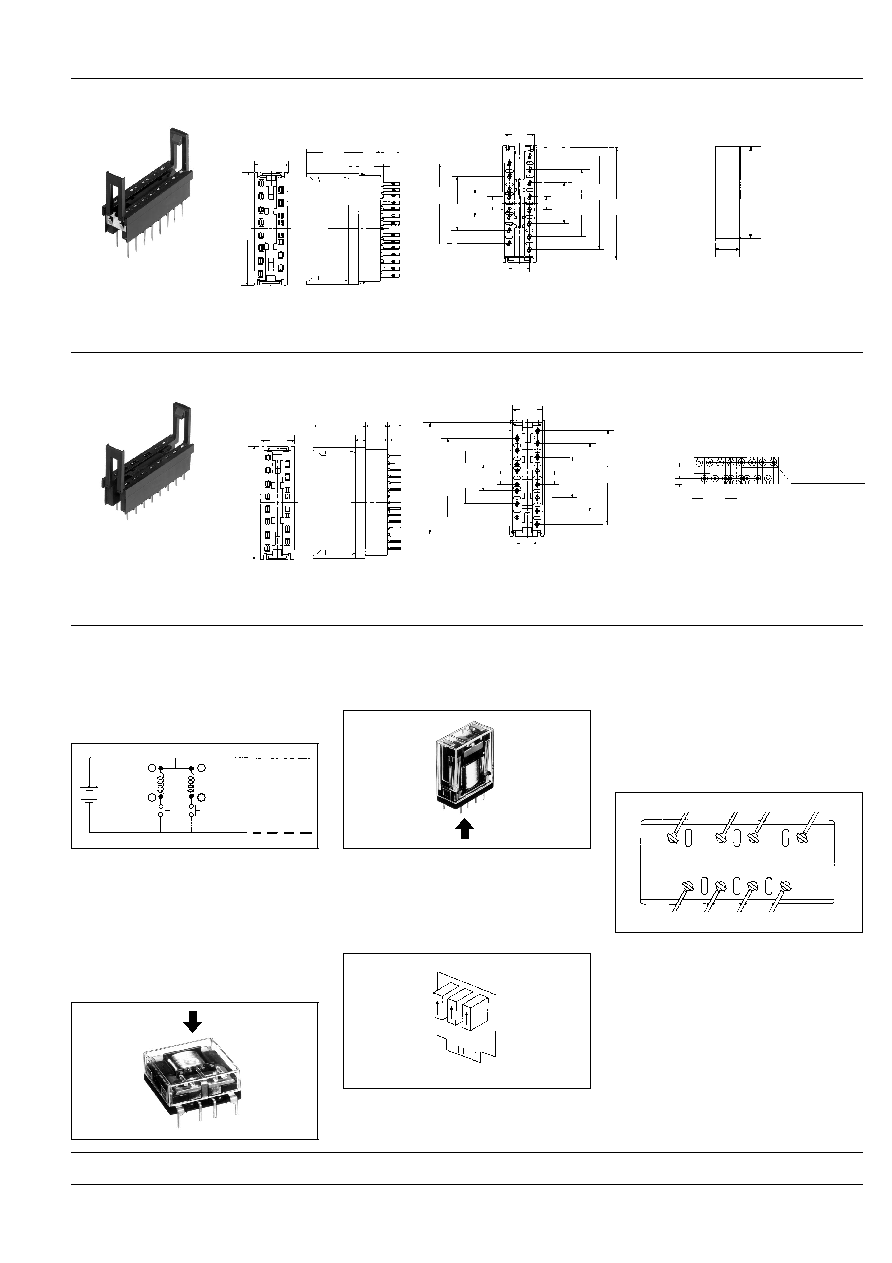
NOTES
1. To maintain insulation between coils of
2 coil latching series, terminals 5 and 6 for
flat series, and terminals 3 and 4 for slim
series should be connected to provide
common return.
2. 2 coil latching series 4C are for intermit-
tent operation only. Power should be ap-
plied to coils continuously for no more
than two minutes.
3. When designing printed circuit board
patterns, note that:
(1) "Top View" wiring diagram is indicated
for the Flat series because terminals can
be seen from above.
(2) "Bottom View" wiring diagram is indi-
cated for the Slim series because termi-
nals can not be seen from above.
4. When using slim series in close proxim-
ity, mount all relays facing the same direc-
tion.
Different mounting directions may cause
change in the relay characteristics be-
cause NC relays are polarized.
5. Sockets
(1) When PC board series are used with
socket, do not apply loads exceeding 3 A.
(2) Soldering should be done quickly to
avoid damaging the thermoplastic body.
(3) Insulation will be optimum when wire
connections are soldered as shown with
all slim sockets.
6
3
5
4
Reset coil
Set coil
Reset switch
Set switch
Same direction
For Cautions for Use, see Relay Technical Information (Page 48 to 76).
9/1/2000
All Rights Reserved, © Copyright Matsushita Electric Works, Ltd.
Go To Online Catalog