 | –≠–ª–µ–∫—Ç—Ä–æ–Ω–Ω—ã–π –∫–æ–º–ø–æ–Ω–µ–Ω—Ç: NR-HLD-5 | –°–∫–∞—á–∞—Ç—å:  PDF PDF  ZIP ZIP |
112
NR-RELAYS
LONG LIFE RELAY
CSA
pending
UL
pending
mm
inch
10
.394
10
.394
20
.787
FEATURES
∑ Sealed construction for automatic wave soldering and cleaning
∑ Latching types available
∑ High sensitivity -- TTL direct drive possible
∑ High speed -- Up to 500 cycle/sec. operations
∑ Wide switching range and high welding resistance
Gold cobalt (AuCo) contact permits
∑ Wider switching range from low level up to high current: 10
µ
A to 1 A
∑ Higher sticking resistance to inrush current
∑ Stable contact resistance from initial stage throughout life
SPECIFICATIONS
Contact
Coil (polarized) (at 25
∞
C
77
∞
F
)
Characteristics (at 25
∞
C
77
∞
F
)
Remarks
*
Specifications will vary with foreign standards certification ratings.
*
1
Measurement at same location as "Initial breakdown voltage" section
*
2
Min. 500M
at 100 V DC between coils of 2 coil latching type
*
3
Detection current: 10mA, Except for between coils of 2 coil latching type
*
4
Excluding contact bounce time
*
5
Half-wave pulse of sine wave: 6ms; detection time: 10
µ
s
*
6
Half-wave pulse of sine wave: 6ms
*
7
Detection time: 10
µ
s
*
8
Although NR relays are rated at 10 G/55 cps. vibration resistance, they will with-
stand up to 60 G/2,000 cps., provided they receive additional support such as
anchoring to the PC board with epoxy resin.
*
9
Refer to 5. Conditions for operation, transport and storage mentioned in
AMBIENT ENVIRONMENT (Page 61)
*
10
Total temperature (ambient temperature plus temperature rise in coil) should not
exceed 90
∞
C
194
∞
F
for single side stable, and 105
∞
C
221
∞
F
for latching relays.
See Reference Data for determination of coil voltage versus temperature.
Arrangement
1 Form C
Initial contact resistance, max.
(By voltage drop 6 V DC 1 A)
60 m
Initial contact pressure
Approx. 5 g
.18 oz
Contact material
Gold cobalt
Electrostatic
capacitance
Contact-
Contact
Sealed type
3 pF
Magnetically
sealed type
4 pF
N.O.
contact-coil
Sealed type
4 pF
Magnetically
sealed type
5 pF
N.C.
contact-coil
Sealed type
5 pF
Magnetically
sealed type
6 pF
Nominal switching capacity
1A 20 VDC,
0.3A 110 VAC
Rating
(resistive)
Max. switching power
33 VA, 20 W
Max. switching voltage
110 V AC, 30 V DC
Max. switching current
AC 0.3 A, DC 1 A
Min. switching power
Approx. 100 mV 10
µ
A
Expected
life (min.
operations)
Mechanical (at 500 cps.)
10
9
Electrical
(resistive)
1 A 20 V DC/
0.3 A 110 V AC
10
6
(at 1 cps.)
0.5 A 30 V DC/
0.1 A 110 V AC
3
◊
10
6
(at 2 cps.)
0.25 A 30 V DC/
0.25 A 30 V AC
5
◊
10
6
(at 5 cps.)
0.2 A 24 V DC/
0.2 A 24 V AC
10
7
(at 25 cps.)
0.1 A 12 V DC/
0.1 A 12 V AC
5
◊
10
7
(at 50 cps.)
0.1 A 9 V DC/
0.1 A 9 V AC
10
8
(at 100 cps.)
Minimum operting power
Single side stable
72 to 133 mW
1 coil latching
41 to 45 mW
2 coil latching
72 to 107 mW
Nominal operating power
Single side stable
147 to 300 mW
1 coil latching
74 to 153 mW
2 coil latching
147 to 331 mW
Max. operating speed
500 cps. (mechanical)
Initial insulation resistance*
1
Min. 1000 M
at 500 V DC*
2
Initial
breakdown
voltage*
3
Between live parts
and ground
1,000 Vrms
Between open
contact
350 Vrms (500 V DC)
Between contact
and coil
1,000 Vrms
Operate time*
4
(at nominal voltage)
Max. 3 ms (Approx. 1 ms)
Release time (without diode)*
4
(at nominal voltage)
Max. 2 ms (Approx. 0.5 ms)
Contact
bounce
time
Single side stable
Approx. 0.5 ms
1-coil /2-coil latching
Approx. 0.3 ms
Temperature rise
Max. 35
∞
C at 0.5 W operating power
Max. 65
∞
C at 1 W operating power
Shock resistance
Functional*
5
Min. 980 m/s
2
{100 G}
Destructive*
6
Min. 980 m/s
2
{100 G}
Vibration
resistance
Functional*
7
98 m/s
2
{10 G}, 10 to 55 Hz
at double amplitude of 1.6 mm*
8
Destructive
117.6 m/s
2
{12 G}, 10 to 55 Hz
at double amplitude of 2 mm
Conditions for opera-
tion, transport and
storage*
9
(Not freez-
ing and condensing
at low temperature)
Ambient
temp.
≠55
∞
C to +65
∞
C*
10
≠67
∞
F to +149
∞
F
Humidity
5 to 85% R.H.
Unit weight
Approx. 7 g
.25 oz
NR
113
TYPICAL APPLICATIONS
Telecommunications equipment, alarm
devices, machine tools, NC machines, au-
tomatic warehouse control, conveyors,
air-conditioners, pressing machines, tex-
tile machinery, elevators, control panels,
pin-board programmers, parking meters,
industrial robots, detectors, annunciators,
optical instruments, business machines,
time recorders, cash registers, copiers,
vending machines, medical equipment.
ORDERING INFORMATION
EX.
Types of case
(Notes) 1. Power types and 1 Form A types are available on request.
(Notes)
2. For UL/CSA recognized types, delete "N" at head portion of part No. and add suffix UL/CSA, when ordering. Ex. RSD-12V UL/CSA
(Notes)
3. Standard packing Carton: 50 pcs., Case: 500 pcs.
Operating function
H: Sealed
S: Magnetically sealed
Nil: Single side stable
L: 1 coil latching
L2: 2 coil latching
Coil voltage (DC)
5, 6, 12, 24, 42 V
NR-
H
L2
D
12V
TYPES AND COIL DATA (at 25
∞
C
77
∞
F
)
Single side stable (NR-SD)
1 coil latching (NR-SLD)
2 coil latching (NR-SL2D)
(Note) Maximum allowable operating power: 1000 mW at 25
∞
C
77
∞
F
.
Nominal coil
voltage, V DC
Pick-up voltage,
V DC (max.)
Drop-out voltage
V DC (min.)
Maximum
allowable voltage,
V DC (40
∞
C
104∞F
)
Coil resistance,
(
±
10%)
Nominal operating
power, mW
Inductance,
Henrys
5
3.5
0.5
13
170
147
0.050
6
4.7
0.6
14
220
164
0.075
12
9.3
1.2
28
890
162
0.3
24
16
2.4
42
2,000
288
0.66
42
28
4.2
85
8,000
221
2.7
Nominal coil voltage,
V DC
Pick-up voltage,
V DC (max.)
Maximum allowable
voltage,
V DC (40
∞
C
104∞F
)
Coil resistance,
(
±
10%)
Nominal operating
power, mW
Inductance,
Henrys
5
3.5
18
340
74
0.12
6
4.3
20
450
80
0.16
12
8.0
30
1,500
96
0.66
24
17
75
6,000
96
2.4
42
23
110
12,000
147
3.9
Nominal coil voltage,
V DC
Pick-up voltage,
V DC (max.)
Maximum allowable
voltage,
V DC (40
∞
C
104∞F
)
Coil resistance,
(
±
10%)
Nominal operating
power, mW
Inductance,
Henrys
Set coil
Reset coil
5
3.5
13.0
170
170
147
0.024
6
4.3
14.0
225
225
160
0.04
12
8.0
26.0
650
650
230
0.14
24
17.0
50.0
2,700
2,700
213
0.35
42
23.0
75.0
5,500
5,500
321
0.8
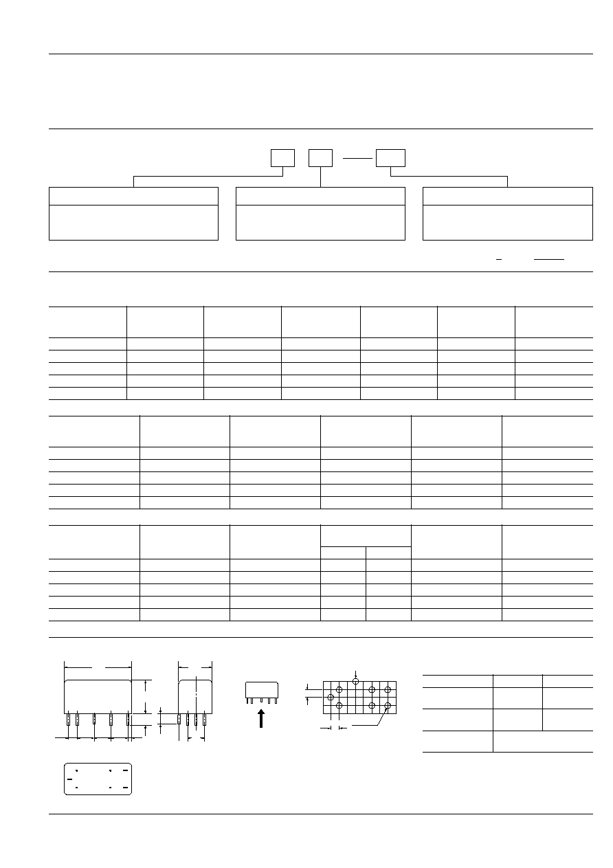
DIMENSIONS
General tolerance:
±
0.5
±
.020
Tolerance:
±
0.2
±
.008
Terminal dimensions (Except soldering)
Soldering: 0.3
.012
max.
2.54
.100
5.1
.201
5.1
.201
5.1
.201
5.1
.201
10
.394
20
.787
3.5
.138
10
.394
3
.118
2.54
.100
2.54
.100
1
2
3
4
5
6
7
1.3 DIA.
.051 DIA.
Ground terminal
Terminal No.
Thickness
Width
1, 7
0.5
.020
0.6
.024
4
0.3
.012
0.7
.028
2, 3, 5, 6,
ground terminal
0.5 DIA.
.020 DIA.
mm
inch
NR
114
DIFFERENCES BETWEEN NR RELAYS AND REED RELAYS
NR relays
Reed relays
Structure
Contact arrangement
1 Form C
1 Form A or 1 Form B
Contact capacity
20 W (high contact pressure)
5 to 15 W
Operating function
Single side stable
Latching
Single side stable
"Getter" hole
Yes
No
"Getter" holes are formed on both pole
shoes to obtain uniform contact resis-
tance throughout life. Film-forming phe-
nomena on contacts is thus fully
prevented.
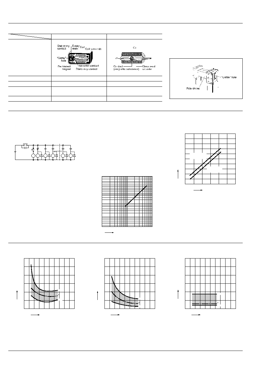
REFERENCE DATA
1.-(1) Contact reliability
Test sample: NR-SD-24V 54 pcs.
Circuits: (A) Following figure with diode
(B) Following figure without diode
Item to be checked: Detect with the circuit stopped
Circuits:
(A) Diode provided: The circuit does not stop through-
out 100 million times.
(B) Diode not provided:
60
= 2.5
◊
10
-8
times
1.-(2) Contact reliability
TEST CONDITION
Sample: NR-SD-24V, 10 pcs.
Contact voltage: 100 mV
Contact current: 10
µ
A
Cycle rate: 50 cps.
Detection level: 100
Testing operation: 3
◊
10
7
m = 1.9
= 2.5
◊
10
7
µ
= 4.7
◊
10
7
95% reliability limit: 1.15
◊
10
7
(Mean time between failure)
2. Coil temperature rise
(under saturated condition)
R
0
R
0
R
54
R
1
R
2
R
52
R
53
R
1
R
2
R
3
R
53
R
54
24 V DC
Stop
Start
10
5
1
0.1
0.2
0.5
1.0
2.0
5.0
10.0
30.0
50.0
70.0
95.0
99.0
99.9
F(t)(%)
No. of operations,
◊
10
7
(WEIBULL)
100
250
500
750
1,000 1,250
90
80
70
60
50
40
30
20
10
Operating power, mW
Coil temperature rise,
∞
C
Magnetically
sealed type
Plastic
sealed type
3.-(1) Operate time including bounce time
(Single side stable)
3.-(2) Operate time including bounce time
(2 coil latching)
4. Release time including bounce time
(Single side stable)
220
180
140
100
60
3.0
2.5
2.0
1.5
1.0
0.5
0
Min.
Max.
x
Coil applied voltage, %V
Operate time, ms
220
180
140
100
60
3.0
2.5
2.0
1.5
1.0
0.5
0
Min.
Max.
x
Coil applied voltage, %V
Operate time, ms
220
180
140
100
60
3.0
2.5
2.0
1.5
1.0
0.5
0
Min.
Max.
x
Coil applied voltage, %V
Release time, ms

NR
115
5.-(1) Leaving at high temperature
(Change of pick-up and drop-out voltages)
Tested sample: NR-SD-24V, 30 pcs.
Condition: Deenergized leaving at 90
∞
C
194
∞
F
(constant temperature)
5.-(2) Leaving at high temperature
(Change of contact resistance)
Tested sample: NR-SD-24V, 30 pcs.
Condition: Deenergized leaving at 90
∞
C
194
∞
F
(constant temperature)
6. High frequency characteristics
Tested sample: NR-SD-24V
Tested condition:
500
1,000
1,500
8
4
12
10
6
2
20
18
16
14
Max.
Max.
Min.
Min.
Time, hr
Voltage, V
x
x
Pick-up voltage
Drop out voltage
100
1,000
10,000
50
100
500
1,000
Max.
Max.
Min.
Min.
Time, hr
Contact resistance, m
N.C. side contact
N.O. side contact
A
SG(Signal generator)
N.C.
Frequency, MHz
Isolation loss between
A and B is measured.
Isolation, dB
N.O.
B
5
10
50
100
≠50
≠100
50
50
7. Contact sticking resistance
TEST CONDITION
The purpose of this test was to confirm contact stick-
ing resistance and contact stability against coil rip-
ples.
Tested Sample: NR-SD-24V, 10 pcs.
Test method: Following coil ripples were applied.
Test period: 500 hours
TEST RESULT
No occurance of sticking was observed.
Contact resistance: Fig. 1
NR-SD-24V: 29 m
to 30.4 m
In actual application, above coil ripples should be
avoided and use of a capacitor in the circuit is recom-
mended to keep the ripple factor below 5%.
8. Distribution of contact resistance
Tested sample: NR-SD-24V (WG type) 105 pcs.
7 V DC
100 Hz
24 V DC
10
100
1,000
50
100
Max.
Min.
x
Energization time, Hr Fig. 1
Contact resistance m
10
20
30
40
50
10
20
30
40
50
Contact resistance, m
Quantity
x = 24.2 m
3
= 9.27 m
9.-(1) Rate of change in pick-up and drop-out
voltage (Single side stable)
9.-(2) Rate of change in pick-up voltage
(2 coil latching)
10.-(1) Mechanical life
(Change of pick-up and drop-out V)
Tested Sample: NR-SD-24V, 10 pcs.
Operation frequency: 500 cps
180
160
140
120
100
80
60
40
20
≠40
≠30
≠20
≠10
0
10
20
30
40
50
60
70
80
90
100
Ambient temperature,
∞
C
Rate of change, %
Drop-out
voltage
Pick-up
voltage
180
160
140
120
100
80
60
40
20
≠40
≠30
≠20
≠10
0
10
20
30
40
50
60
70
80
90
100
Ambient temperature,
∞
C
Rate of change, %
Pick-up
voltage
1,000
10,000
100,000
5
10
15
Min.
Max.
Min.
Max.
No. of operations,
◊
10
4
Pick-up/drop-out Voltage, V
Pick-up Voltage
Drop-out Voltage
10.-(2) Mechanical life
(Change of contact resistance)
Tested Sample: NR-SD-24V, 10 pcs.
Operation frequency: 500 cps
11.-(1) Electrical life
(1 A 20 V DC resistive load)
Tested sample: NR-SD-24V, 10 pcs.
11.-(2) Electrical life
Tested Sample: NR-SD-24V, 10 pcs.
Load: 60 mA 24 V DC resistive load
Frequency: 50 cps
1,000
10,000
100,000
50
40
30
20
10
60
70
80
90
Min.
Max.
No. of operations,
◊
10
4
Contact resistance, m
N.C. side
N.O. side
10
5
1
0.1
0.2
0.5
1.0
2.0
5.0
10.0
30.0
50.0
70.0
95.0
99.0
99.9
F(t)(%)
No. of operations,
◊
10
4
: 1.85
◊
10
6
µ
: 1.65
◊
10
6
: 5.64
◊
10
4
(Weibull probability paper)
100
1,000
1,0000
50
100
150
No. of operations,
◊
10
4
Contact resistance, m
N.C. side
N.O. side

NR
116
11.-(3) Electrical life
Tested Sample: NR-SD-12V, 10 pcs.
Load: 54 mA 12 V DC inductive load
with diode protection
(4 relay coils in parallel of NR-SD-12V)
Frequency: 50 cps
11.-(4)Electrical life
(327 mA 24 V DC relay coil load)
Tested sample: NR-SD-24V, 5 pcs.
Condition: HP2-DC24
◊
6 pcs. in parallel,
diode protector provided
1,000
10,000
100
1,000
Max.
Min.
No. of operations,
◊
10
4
Contact resistance, m
100
200
300
8
4
0
12
16
Min.
Min.
Max.
Max.
x
x
No. of operations,
◊
10
4
Pick-up/drop-out voltage, V
Pick-up voltage
Drop-out voltage
L
1
L
2
L
3
L
4
L
5
L
6
100
200
300
80
100
40
20
60
x
Min.
No. of operations,
◊
10
4
Contact resistance, m
24 V DC
NR relay contact
L1~L6: HP2-DC24V
◊
6 pcs. in parallel
Diode protector provided
Max.
12. Thermal electro motive force
Tested Sample: NR-SD-12V, 5 pcs.
Coil applied V: 12 V DC
Ambient atmosphere: 25
∞
C
77∞F
, 60% RH
13. High temperature test
TEST CONDITION
Tested Sample: NR-SD-24V, 30 pcs.
Ambient temperature: 80
∞
C
176∞F
Humidity: less than 50% R.H.
Exposure time: 2,000 hours with relays deenergized.
TEST RESULT
Contact resistance: Fig. 1
All samples were measured less than
100 m
in contact resistance throughout this test.
14. Influence of adjacent mounting
mm
inch
15. Resistive load test
TEST CONDITION
Tested Sample: NR-SD-24V, 10 pcs.
Load: 1 A 20 V DC Resistive
Cycle rate: 1.4 cps.
Contact resistance in life test
2
4
6
8
10
12
14
16
100
200
Hour
Thermal EMF,
µ
V
N.C.
N.O.
10
20
40
60
80
100
100
1,000 2,000
Exposure time, hr
Contact resistance, m
Max.
Max.
Min.
Distance
0
(0)
5
(.197)
10
(.394)
15
(.591)
Type
Magnetically
shielded type
±
5%
±
1%
0
0
Sealed type
--
±
10%
±
6%
±
2%
No. of operations,
◊
10
6
1
20
50
100
500
N.C.
Max.
Max.
Mean value
of N.O.
Mean value
of N.C.
Min.
Min.
N.O.
2
5
10
15
Contact resistance, m
APPLICATION HINTS
Contact protection circuit
When using NR relays in inductive load circuits, a contact protection circuit is recommended.
Examples:
CR
CR
Diode
1. r = more than 20 to 30 ohms
2. In an AC circuit impedance of L is to be
somewhat smaller than impedance of r
and c.
Can be used for both AC and DC circuits.
Use 500 to 1000 ohms for r and 0.1
µ
F to
0.2
µ
F 200 V for c in a general 12 to 24 V
load circuit.
For DC circuits only.
S
Relay contact
: Inductive load
r
c
L
L
r
S
c
L
S
L