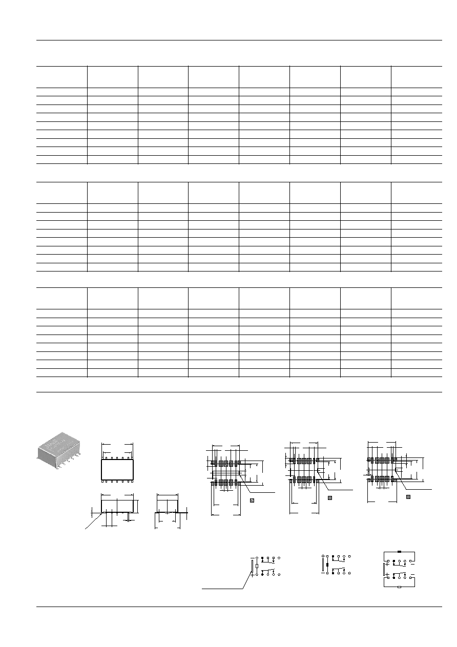
80
RA
9.7
.382
5.9
.232
14.70
.579
mm
inch
1. High frequency characteristics
(Impedance 50
, ~1.0GHz)
∑ Insertion loss; Max. 0.3dB
∑ Isolation; Min. 20dB (Between open
contacts)
Min. 30dB (Between contact
sets)
∑ V.S.W.R.; Max. 1.2
2. Surface mount terminal
This relay is a surface-mounted model
with excellent high-frequency proper-
ties. In addition, it can use a microstrip
line in the base circuit design which
spares the labor of machining the base.
3. Low profile small type
9.7(W)
◊
14.7(L)
◊
5.9(H) mm
.382(W)
◊
.579(L)
◊
.232(H) inch
4. High sensitivity: 140 mW nominal
operating power
5. High contact reliability
Electrical life: Min. 10
7
(10mA 10V DC)
Remarks
* Specifications will vary with foreign standards certification ratings.
*
1
Measurement at same location as "Initial breakdown voltage" section.
*
2
Detection current: 10mA
*
3
Nominal operating voltage applied to the coil, excluding contact bounce time.
*
4
By resistive method, nominal voltage applied to the coil: 3W contact carrying
power: at 1.0GHz, Impedance 50
, V.S.W.R. Max.1.2
*
5
Half-wave pulse of sine wave: 11ms, detection time: 10
µ
s.
*
6
Half-wave pulse of sine wave: 6ms
*
7
Detection time: 10
µ
s
*
8
Refer to 5. Conditions for operation, transport and storage mentioned in
AMBIENT ENVIRONMENT (Page 61)
Contact
Arrangement
2 Form C
Contact material
Gold-clad silver alloy
Initial contact resistance
Max. 75m
Rating
Contact rating (resistive)
10mA 10 V DC
1A 30 V DC
Contact carrying power
Max. 3W(at 1.0GHz, imped-
ance 50
, V.S.W.R. max.1.2)
Max. switching voltage
30 V DC
Max. switching current
1A
High fre-
quency
character-
istics
(~1GHz,
Imped-
ance 50
)
Isolation
Between
open con-
tacts
Min. 20dB
Between
contact
sets
Min. 30dB
Insertion loss
Max. 0.3dB
V.S.W.R.
Max. 1.2
Input power
Max. 3W(at 1.0GHz, imped-
ance 50
, V.S.W.R. max.1.2)
Nominal
operating
power
Single side stable
140mW (1.5 to 12V)
200mW (24V)
300mW (48V)
1 coil latching
70 mW (1.5 to 12V)
100mW (24V)
2 coil latching
140mW (1.5 to 12V)
200mW (24V)
Expected
life (min.
operation)
Mechanical (at 180 cpm)
10
8
Electrical
(at 20 cpm)
10mA 10 V
DC(resis-
tive load)
10
7
1A 30 V DC
(resistive
load)
10
5
Characteristics
Initial insulation resistance *
1
Min. 100 M
(at 500 V DC)
Initial breakdown
voltage *
2
Between open con-
tacts
750 Vrms for 1 min.
Between contact
sets
1,000 Vrms for 1 min.
Between contact
and coil
1,000 Vrms for 1 min.
Between contact
and earth terminal
1,000 Vrms for 1 min.
Operate time [Set time] *
3
(at 20
∞
C)
Max. 4ms (Approx. 2ms)
[Max. 4ms (Approx. 2ms)]
Release time (without diode) [Reset time]
*
3
(at 20
∞
C)
Max. 4ms (Approx. 1ms)
[Max. 4ms (Approx. 2ms)]
Temperature rise (at 20
∞
C) *
4
Max. 60
∞
C
Shock resistance
Functional *
5
500 m/s
2
Destructive *
6
1,000 m/s
2
Vibration resistance
Functional *
7
10 to 55 Hz at double
amplitude of 3mm
Destructive
10 to 55 Hz at double
amplitude of 5mm
Conditions for oper-
ation, transport and
storage *
8
(Not freezing and
condensing at low
temperature)
Ambient temp
≠40
∞
C to +85
∞
C
≠40∞F to +185∞F
Humidity
5 to 85% R.H.
Unit weight
Approx. 2g
.07oz
SPECIFICATIONS
TYPICAL APPLICATIONS
∑ Measurement instruments
Oscilloscope attenuator circuit
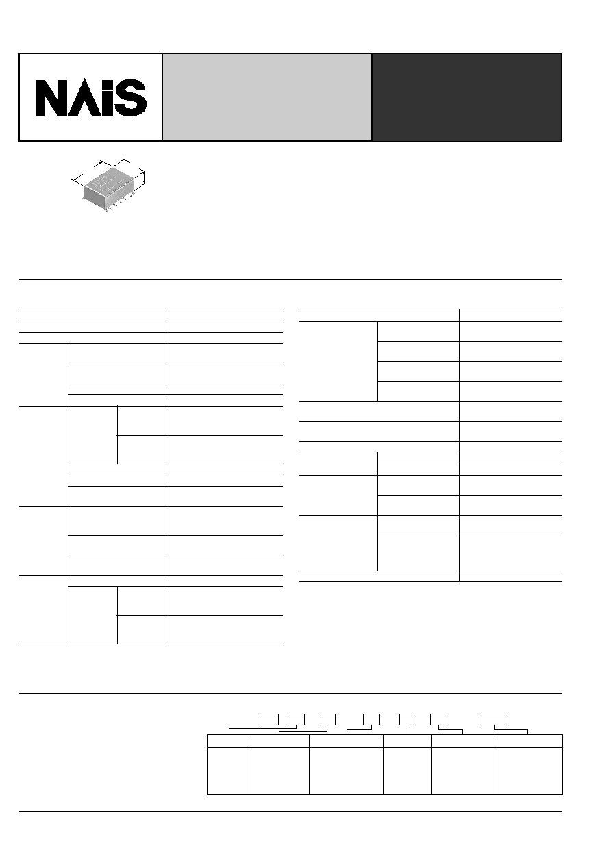
0
0
A
03
2
A
Ex.
Operating function
0: Single side stable
1: 1 coil latching
2: 2 coil latching
Contact arrangement
2: 2 Form C
RA
Product name
RA
Note: Standard packing; Carton: 40 pcs. Case 1,000 pcs.
0: Standard
type
(B.B.M)
A: Surface-mount
terminal
Type of operation Terminal shape
1H: 1.5
03: 3
4H: 4.5
05: 5
06: 6
09: 9
12: 12
24: 24
48: 48
Coil voltage, V DC
ORDERING INFORMATION
FEATURES
MICROWAVE RELAY
FOR ATTENUATOR
CIRCUIT
RA-RELAYS

82
RA
REFERENCE DATA
1. High frequency characteristics
Sample: ARA200A12
Measuring method: Measured with HP network analyzer (HP8753C).
∑ Insertion loss
∑ Isolation
∑ V.S.W.R.
0.8
1.0
0
0.2
0.6
0.4
0.3
300kHz
0.5GHz
1.0GHz
COM-NC
COM-NO
Insertion loss, dB
Frequency
80
100
0
20
30
60
40
300kHz
0.5GHz
1.0GHz
COM-NC
COM-NO
CONTACT sets
Isolation, dB
Frequency
1.1
1.0
1.5
1.4
1.2
1.3
300kHz
0.5GHz
1.0GHz
COM-NO
COM-NC
Frequency
V.S.W.R.
NOTES
1. Coil operating power
Pure DC current should be applied to the
coil. The wave form should be rectangu-
lar. If it includes ripple, the ripple factor
should be less than 5%.
However, check it with the actual circuit
since the characteristics may be slightly
different. The nominal operating voltage
should be applied to the coil for more
than 10 ms to set/reset the latching type
relay.
2. Coil connection
When connecting coils, refer to the wiring
diagram to prevent mis-operation or mal-
function.
3. External magnetic field
Since RA relays are highly sensitive po-
larized relays, their characteristics will be
affected by a strong external magnetic
field. Avoid using the relay under that
condition.
4. Cleaning
For automatic cleaning, the boiling meth-
od is recommended. Avoid ultrasonic
cleaning which subjects the relays to high
frequency vibrations, which may cause
the contacts to stick.
It is recommended that alcoholic solvents
be used.
5. Soldering
Manual soldering shall be performed un-
der following condition.
Tip temperature: 280∞C to 300∞C
.536∞F
to 572∞F
Wattage: 30 to 60W
Soldering time: within 5s
In case of automatic soldering, the follow-
ing conditions should be observed
1) Position of measuring temperature
2) IR (infrared reflow) soldering method
Temperature rise of relay itself may vary
according to the mounting level or the
heating method of reflow equipment.
Therefore, please set the temperature of
soldering portion of relay terminal and
the top surface of the relay case not to
exceed the above mentioned soldering
condition.
It is recommended to check the tempera-
ture rise of each portion under actual
mounting condition before use.
The soldering earth shall be performed
by manual soldering.
B
1.0mm
.039inch
A: Surface of PC board where relay is mounted.
B: Above the PC board surface.
A
T
1
T
2
T
3
T
4
T
5
t
1
t
3
t
4
t
5
t
2
A:
B:
t
2
- t
1
= 80 to 120 s
t
5
- t
3
= 30 to 40 s
t
4
= 170 to 190 s
T
1
=150
∞
C
302
∞
F
T
2
=160
∞
C
320
∞
F
T
3
=183
∞
C
361
∞
F
T
4
=245
∞
C
473
∞
F
T
5
=270
∞
C
518
∞
F
For Cautions for Use, see Relay Technical Information (Page 48 to 76).
9/1/2000
All Rights Reserved, © Copyright Matsushita Electric Works, Ltd.
Go To Online Catalog