 | –≠–ª–µ–∫—Ç—Ä–æ–Ω–Ω—ã–π –∫–æ–º–ø–æ–Ω–µ–Ω—Ç: RK1R-9V | –°–∫–∞—á–∞—Ç—å:  PDF PDF  ZIP ZIP |
101
RK-RELAYS
1.5 GHz MICROWAVE RELAY
mm
inch
11.2
.441
9.7
.382
20.2
.795
∑ Excellent high frequency characteristics
Isolation: Min. 60dB (at 1.5 GHz)
Insertion loss: Max. 0.3dB (at 900 MHz)
∑ V.S.W.R.: Max. 1.5 (at 900MHz)
∑ High sensitivity in small size
Size: 20.2
◊
11.2
◊
9.7 mm
.795
◊
.441
◊
.382 inch
Nominal power consumption: 200 mW (single side stable type)
∑ Sealed construction for automatic cleaning
∑ Latching types are also available
Arrangement
Contact
Coil (at 25
∞
C,
68
∞
F
)
Contact material
Max. switching voltage
Isolation
Max. switching current
Insertion loss
0.01 A 24 V DC
10 W 1.2 GHz
3
◊
10
5
10
5
V.S.W.R.
Min. 60 dB (at 1.5 GHz)
Max. 0.3 dB (at 900 MHz)
Max. 1.5 (at 900 MHz)
2 coil latching
Single side stable
200 mW
Nominal operating power
1 coil latching
400 mW
200 mW
Initial contact resistance, max.
(By HP4328A)
1 Form C
Gold-clad
100 m
Nominal switching
capacity
High frequency
characteristics
(Impedance 50
)
Expected
life (min.
operations)
5
◊
10
6
Electrical
Mechanical
Rating
Max. switching power
30 V DC
0.5 A
0.01 A 24 V DC 10 W (at
1.2 GHz, Impedance 50
)
10 W
Characteristics
Initial insulation resistance*
1
Operate time [Set time]*
3
(at nominal voltage)
Approx. 6 ms [Approx. 5ms]
Max. 60
∞
Cwith nominal coil
voltage across coil and at
nominal switching capacity
Temperature rise
Initial
breakdown
voltage*
2
Between open contacts
Between contact and coil
Between contact and
earth terminal
500 Vrms
1,000 Vrms
500 Vrms
Min. 100 M
at 500 V DC
Shock resistance
Vibration
resistance
Unit weight
Remarks
*
Specifications will vary with foreign standards certification ratings.
*
1
Measurement at same location as "Initial breakdown voltage" section
*
2
Detection current: 10mA
*
3
Excluding contact bounce time
*
4
Half-wave pulse of sine wave: 11ms, detection time: 10
µ
s
*
5
Half-wave pulse of sine wave: 6ms
*
6
Detection time: 10
µ
s
Approx. 4.4 g
.155 oz
Min. 196 m/s
2
{20 G}
Min. 980 m/s
2
{100 G}
Functional*
4
Destructive*
5
Functional*
6
Destructive
10 to 55 Hz
at double amplitude of 3 mm
10 to 55 Hz
at double amplitude of 5 mm
Conditions for operation,
transport and storage
(Not freezing and condensing
at low temperature)
Ambient temp.
Humidity
≠40
∞
C to 60
∞
C
≠40
∞
F to 140
∞
F
5 to 85% R.H.
Release time (without diode) [Reset time]*
3
(at nominal voltage)
*
2
Approx. 3 ms [Approx. 5ms]
TYPICAL
APPLICATIONS
∑ Audio visual equipment
broadcast satellite tuners
VCRs, CATVs, TVs
∑ Communication equipment
automobile telephones
maritime telephones
∑ Instrumentation
test equipment
measuring equipment
ORDERING INFORMATION
1
Ex. RK
L2
Contact arrangement
1: Standard type
1R: R type
(See Schematic on next page.)
Note: Standard packing; Carton: 50 pcs. Case 500 pcs.
Nil: Single side stable
L: 1 coil latching
L2: 2 coil latching
3, 4.5, 5, 6, 9, 12,
24 V
Operating function
Coil voltage, DC
24V
SPECIFICATIONS
RK
102
Part No.
RK1-3V
3
2.25
0.3
45
66.7
200
200
3.3
5
3.75
0.5
125
40
.7
200
5.5
6
4.5
0.6
180
33.3
200
6.6
9
6.75
0.9
405
22.2
200
9.9
12
9
1.2
720
16.7
200
13.2
RK1-5V
RK1-6V
RK1-9V
RK1-12V
24
18
2.4
2,880
8.3
200
26.4
RK1-24V
RK1R-3V
RK1-4.5V
4.5
3.38
0.45
101
44.4
4.95
RK1R-4.5V
RK1R-5V
RK1R-6V
RK1R-9V
RK1R-12V
RK1R-24V
Nominal
voltage,
V DC
Pick-up
voltage, max.
V DC
Drop-out
voltage, min.
V DC
Coil
resistance,
(
±
10%)
Nominal
operating
current, mA
Nominal
operating
power, mW
Maximum.
allowable
voltage, V DC
(at 60
∞
C
140
∞
F
)
∑ Single side stable type
Part No.
RK1-L-3V
3
2.25
2.25
45
66.7
200
3.3
5
3.75
3.75
125
40
200
5.5
6
4.5
4.5
180
33.3
200
6.6
9
6.75
6.75
405
22.2
200
9.9
12
9
9
720
16.7
200
13.2
RK1-L-5V
RK1-L-6V
RK1-L-9V
RK1-L-12V
24
18
18
2.25
3.75
4.5
6.75
9
18
2,880
8.3
200
26.4
RK1-L-24V
RK1R-L-3V
RK1-L-4.5V
4.5
3.38
3.38
101
44.4
200
4.95
RK1R-L-4.5V
RK1R-L-5V
RK1R-L-6V
RK1R-L-9V
RK1R-L-12V
RK1R-L-24V
Nominal
voltage,
V DC
Set
voltage, max.
V DC
Reset
voltage, max.
V DC
Coil
resistance,
(
±
10%)
Nominal
operating
current, mA
Nominal
operating
power, mW
Maximum.
allowable
voltage, V DC
(at 60
∞
C
140
∞
F
)
∑ 1 coil latching type
Part No.
RK1-L2-3V
3
2.25
22.5
133.3
400
3.3
5
3.75
62.5
80
400
5.5
6
4.5
90
66.7
400
6.6
9
6.75
202.5
44.4
400
9.9
12
9
360
33.3
400
13.2
RK1-L2-5V
RK1-L2-6V
RK1-L2-9V
RK1-L2-12V
24
18
1,440
16.7
400
26.4
RK1-L2-24V
RK1R-L2-3V
3.38
RK1-L2-4.5V
4.5
3.38
50.6
88.9
400
4.95
RK1R-L2-4.5V
RK1R-L2-5V
RK1R-L2-6V
RK1R-L2-9V
RK1R-L2-12V
RK1R-L2-24V
Nominal
voltage,
V DC
Set
voltage, max.
V DC
Reset
voltage, max.
V DC
Coil
resistance,
(
±
10%)
Nominal
operating
current, mA
Nominal
operating
power, mW
Maximum.
allowable
voltage, V DC
(at 60
∞
C
140
∞
F
)
∑ 2 coil latching type
14
≠1
+7
N.C.
COM
N.O.
13 12 11 10 9
8
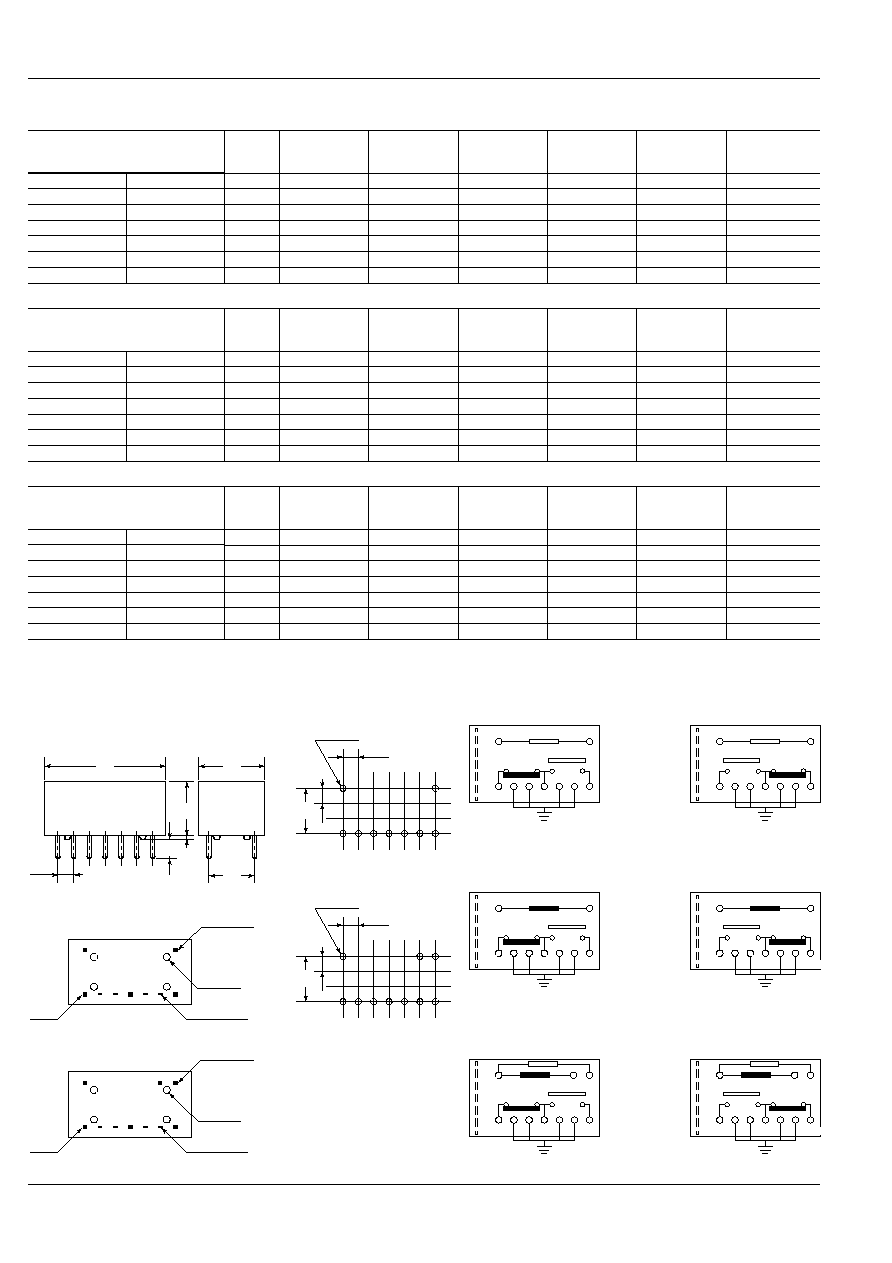
Standard contact arrangement
PC board pattern (Copper-side view)
Schematic (Bottom view)
mm
inch
RK1
Single side
stable
(Deenergized
condition)
7.62
.300
10-0.9 dia.
10-.035 dia.
2.54
.100
2.54
.100
(2 coil latching)
Tolerance:
±
0.1
±
.003
3-0.6
◊
0.3
3-.024
◊
.012
4-0.6
◊
0.25
4-.024
◊
.010
3-0.45
3-.018
Stand-off
(2 coil latching)
General tolerance:
±
0.3
±
.012
14
6
+
≠
+
1
7
RESET
COM
SET
13 12 11 10 9
8
RK1-L2
2 coil
latching
(Reset
condition)
6
+
≠
+
1
7
14
SET
COM
RESET
13 12 11 10 9
8
RK1R-L2
14
+1
≠7
SET
COM
RESET
13 12 11 10 9
8
RK1R-L
14
≠1
+7
N.O.
COM
N.C.
13 12 11 10 9
8
R type contact arrangement
RK1R
7.62
.300
9-0.9 dia.
9-.035 dia.
2.54
.100
2.54
.100
(Single side stable and
1 coil latching)
2-0.6
◊
0.3
2-.024
◊
.012
4-0.6
◊
0.25
4-.024
◊
.010
3-0.45
3-.018
Stand-off
(Single side stable and
1 coil latching)
14
+1
≠7
RESET
COM
SET
13 12 11 10 9
8
RK1-L
1 coil
latching
(Reset
condition)
9.1
.358
7.62
.300
3.5
.138
2.54
.100
0.6
.024
20.2
.795
11.2
.441
TYPES ANE COIL DATA (at 20∞C
68∞F
)
DIMENSIONS
RK
103
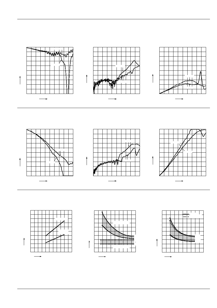
REFERENCE DATA
1.-(1) High frequency characteristics (Impedance 75
)
Sample: RK1-12V
Measuring method: Measured with HP network analyzer (HP8753C)
∑ Insertion loss characteristics
∑ Isolation characteristics
∑ V.S.W.R. characteristics
0.8
1.0
0
0.2
0.6
0.4
300kHz
1.5GHz
3GHz
COM-NC
COM-NO
Frequency
Insertion loss, dB
80
100
0
20
60
40
300kHz
1.5GHz
3GHz
COM-NC
COM-NO
Frequency
Isolation, dB
1.2
1.0
2.0
1.8
1.4
1.6
300kHz
1.5GHz
3GHz
COM-NO
COM-NC
Frequency
V.S.W.R.
1.-(2) High frequency characteristics (Impedance 50
)
Sample: RK1-5V
Measuring method: Measured with HP network analyzer (HP8753C)
∑ Insertion loss characteristics
∑ Isolation characteristics
∑ V.S.W.R. characteristics
0.8
1.0
0
0.2
0.6
0.4
300kHz
1.5GHz
3GHz
COM-NC
COM-NO
Frequency
Insertion loss, dB
80
100
0
20
60
40
300kHz
1.5GHz
3GHz
COM-NC
COM-NO
Frequency
Isolation, dB
1.2
1.0
2.0
1.8
1.4
1.6
300kHz
1.5GHz
3GHz
COM-NO
COM-NC
Frequency
V.S.W.R.
2. Coil temperature rise
Sample: RK1-12V, RK1-L-12V, RK1-L2-12V
No. of samples: n = 6
Carrying current: 10 mA
Ambient temperature: 25∞C
77∞F
3.-(1) Operate/Release time
(Single side stable)
Sample: RK1-12V; No. of samples: n = 6
3.-(2) Set/Reset time (Latching)
Sample: RK1-L-12V, RK1-L2-12V
No. of samples: n = 12
0
20
40
60
80
100
80
100
130
150
RK1-L2-12V
RK1-12V,
RK1-L-12V
Voltage applied to coil, %V
Temperature rise,
∞
C
0
2
4
6
8
10
80
100
120
150
Max.
Min.
Max.
Min.
Voltage applied to coil, %V
Operate/Reset time, ms
Operate time
Release time
0
2
4
6
8
10
80
100
130
Max.
Min.
Max.
Min.
Set time
Reset time
Voltage applied to the coil (%V)
Set/Reset time, ms

RK
104
4.-(1) Mechanical life test (Single side stable)
Sample: RK1-12V; No. of samples: n = 12
4.-(2) Mechanical life test (Latching)
Sample: RK1-L2-12V
No. of samples: n = 12
4.-(3) Mechanical life test
Sample: RK1-12V
No. of samples: n = 20 (20
◊
2 contacts)
0
2
4
6
8
10
12
100
500 1,000
Min.
Max.
Min.
Max.
No. of operations,
◊
10
4
Pick-up/drop-out voltage, V
Pick-up voltage
Drop-out voltage
0
2
4
6
8
10
12
100
500 1,000
Min.
Max.
No. of operations,
◊
10
4
Set/Reset voltage, V
0
50
100
150
200
250
300
50
100
500 1,000
Min.
Max.
No. of operations,
◊
10
4
Contact resistance, m
5. Electrical life test (0.01 A 24 V DC)
Sample: RK1-12V; No. of samples: n = 6
6. Ambient temperature characteristics
Sample: RK1-12V; No. of samples: n = 6
7. Contact resistance distribution (initial)
Sample: RK1-12V
No. of samples: n = 50 (50
◊
2 contacts)
0
2
4
6
8
10
12
10
20
30
Min.
Max.
Min.
Max.
No. of operations,
◊
10
4
Pick-up/drop-out voltage, V
Pick-up voltage
Drop-out voltage
≠40
≠40
≠20
≠4
0
20
68
40
20
≠20
≠40
Rate of change, %
Ambient temperature,
∞
C
∞
F
40
104
60
140
80
176
Pick-up voltage
Drop-out voltage
0
10
20
30
40
50
10
20
30
40
50
Contact resistance, m
Quantity
8.-(1) Influence of adjacent mounting
Sample: RK1-12V; No. of sample: n = 10
8.-(2) Influence of adjacent mounting
Sample: RK1-12V; No. of samples: n = 10
≠10
0
10
≠10
0
10
5
.197
10
.394
ON ON
OFF OFF
OFF condition
ON condition
Inter-relay distance, (mm,
inch
)
Rate of change, %
Rate of change, %
Pick-up voltage
Drop-out voltage
ON
ON
OFF
OFF
≠10
0
10
≠10
0
10
5
.197
10
.394
0
10
OFF condition
Inter-relay distance, (mm,
inch
)
Rate of change, %
Rate of change, %
ON condition
Drop-out voltage
Pick-up voltage
NOTES
1. Soldering
Perform soldering under the conditions
below.
∑ Within 10 s at 260∞C
500∞F
∑ Within 3 s at 350∞C
662∞F
2. Latching relay
In order to assure proper operating re-
gardless of changes in the ambient usage
temperature and usage conditions, nomi-
nal operating voltage should be applied to
the coil for more than 30 ms to set/reset
the latching type relay.
For Cautions for Use, see Relay Technical Information (Page 48 to 76).
9/1/2000
All Rights Reserved, © Copyright Matsushita Electric Works, Ltd.
Go To Online Catalog