 | –≠–ª–µ–∫—Ç—Ä–æ–Ω–Ω—ã–π –∫–æ–º–ø–æ–Ω–µ–Ω—Ç: SF2-DC36V | –°–∫–∞—á–∞—Ç—å:  PDF PDF  ZIP ZIP |
258
SF
POLARISED, MONOSTABLE
SAFETY RELAY with
(mechanical linked) forced
contacts operation
SF-RELAYS
(SF3 pending) (SF3 pending)
(SF3 pending)
FEATURES
∑ Forced operation contacts (2 Form A
2 Form B, 3 Form A 1 Form B)
N.O. and N.C. side contacts are
connected through a card so that one
interacts with the other in movement. In
case of a contact welding, the other
keeps a min. 0.5mm
.020inch
contact
gap.
∑ Independent operation contacts
(4 Form A 4 Form B)
Each pair of contacts is free from the
main armature and is independent from
each other. So if a N.O. pair of contacts
are welded, the other 3 N.O. contacts are
not effected (operate properly) That
enables to plan a circuit to detect welding
or go back to the beginning condition.
∑ Separated chamber structure
(2 Form A 2 Form B, 3 Form A 1 Form B,
4 Form A 4 Form B)
N.O. and N.C. side contacts are put in
each own space surrounded with a card
and a body-separater. That prevents
short circuit between contacts, which is
caused by their springs welding or
damaged.
∑ UL/CSA, TÐV, SEV approved
(UL/CSA, SEV of SF3 pending)
25.0
.984
16.5
±
0.3
.650
±
.012
53.3
±
0.3
2.098
±
.012
25.0
.984
16.5
±
0.3
.650
±
.012
53.3
±
0.3
2.098
±
.012
33
±
0.3
1.299
±
.012
16.5
±
0.3
.650
±
.012
53.3
±
0.3
2.098
±
.012
mm
inch
SPECIFICATIONS
ORDERING INFORMATION
Ex. SF
2
DC 12 V
Contact arrangement
Coil voltage
DC 5, 9, 12, 18, 21,
24, 36, 48, 60 V
2: 2 Form A 2 Form B
3: 3 Form A 1 Form B
4: 4 Form A 4 Form B
UL/CSA, TÐV, SEV approved type is standard (SF2, SF4)
TÐV approved type is standard (SF3)
TYPICAL APPLICATIONS
∑ Signal
∑ Escalator
∑ Elevator
∑ Medical Instruments
∑ Railway
∑ Factory Automation
Remarks
* Specifications will vary with foreign standards certification ratings.
*1
More than 10
5
operations when applying the nominal switching capacity to one
side of contact pairs of each Form A contact and Form B contact
*2
Measurement at same location as " Initial breakdown voltage " section
*3
Detection current: 10mA
*4
Excluding contact bounce time
*5
Half-wave pulse of sine wave: 11ms; detection time: 10
µ
s
*6
Half-wave pulse of sine wave: 6ms
*7
Detection time: 10
µ
s
*8
Refer to 5. Conditions for operation, transport and storage mentioned in
AMBIENT ENVIRONMENT (Page 61).
Contact
Type
SF2
SF3
SF4
Arrangement
2 Form A
2 Form B
3 Form A
1 Form B
4 Form A
4 Form B
Initial contact resistance, max.
(By voltage drop 6 V DC 1 A)
30 m
Contact material
Gold-flashed silver alloy
Rating
(resistive)
Nominal switching
capacity
6 A 250 V AC, 6 A 30 V DC
Max. switching power
1,500 VA, 180 W
Max. switching voltage
30 V DC, 440 V AC
Max. carrying current
6 A DC, AC
Expected
life (min.
operations)
Mechanical (at 180
cpm) (resistive)
10
7
Electrical (at 20 cpm)
3
◊
10
4
*
1
10
5
Coil
(at 25∞C
77∞F
)
Nominal operating power
500 mW
Characteristics
(at 25∞C
77∞F
, 50% Relative humidity)
SF2
SF3
SF4
Max. operating speed
180 cpm (at nominal voltage)
Initial insulation resistance*
2
Min. 1,000 M
at 500 V DC
Initial break-
down voltage*
3
Between con-
tact sets
2,500 Vrms
Between open
contacts
2,500 Vrms
Between con-
tact and coil
2,500 Vrms
Operate time*
4
(at nominal voltage)
Approx. 17 ms
Approx. 18 ms
Release time (without diode)*
4
(at nominal voltage)
Approx. 7 ms
Approx. 6 ms
Temperature rise
(at nominal voltage)
Max. 45
∞
C with nominal coil voltage
and at 6 A switching current
Shock
resistance
Functional*
5
Min. 294 m/s
2
{30 G}
Destructive*
5
Min. 980 m/s
2
{100 G}
Vibration
resistance
Functional*
7
117.6 m/s
2
{12 G}, 10 to 55 Hz
at double amplitude of 2 mm
Destructive
117.6 m/s
2
{12 G}, 10 to 55 Hz
at double amplitude of 2 mm
Conditions for oper-
ation, transport and
storage*
8
(Not freezing and
condensing at low
temperature)
Ambient
temp.
≠40
∞
C to +70
∞
C
≠40∞F to +158∞F
Humidity
5 to 85% R.H.
Unit weight
37 g
1.31 oz
47 g
1.66 oz
259
SF
TYPES AND COIL DATA (at 20∞C
68∞F
)
Contact
arrangement
Part No.
Nominal
voltage, V DC
Pick-up
voltage, VDC
(max.)
Drop-out
voltage, V DC
(min.)
Coil
resistance
(
±
10%)
Nominal
operating
current,
mA(
±
10%)
Nominal
operating
power, mW
Max. allowable
voltage, V DC
SF2
SF2-DC5V
5
3.75
0.5
50
100
500
6
SF2-DC9V
9
6.75
0.9
500
10.8
SF2-DC12V
12
9
1.2
288
41.7
500
14.4
SF2-DC18V
18
13.5
1.8
500
21.6
SF2-DC21V
21
15.75
2.1
500
25.2
SF2-DC24V
24
14.4
2.4
1.152
20.8
500
28.8
SF2-DC36V
36
27
3.6
500
43.2
SF2-DC48V
48
36
4.8
4.608
10.4
500
57.6
SF2-DC60V
60
45
6.0
7.200
8.3
500
72
SF3
SF3-DC5V
5
3.75
0.5
50
100
500
6
SF3-DC9V
9
6.75
0.9
500
10.8
SF3-DC12V
12
9
1.2
288
41.7
500
14.4
SF3-DC18V
18
13.5
1.8
500
21.6
SF3-DC21V
21
15.75
2.1
500
25.2
SF3-DC24V
24
14.4
2.4
1.152
20.8
500
28.8
SF3-DC36V
36
27
3.6
500
43.2
SF3-DC48V
48
36
4.8
4.608
10.4
500
57.6
SF3-DC60V
60
45
6.0
7.200
8.3
500
72
SF4
SF4-DC5V
5
3.75
0.75
50
100
500
6
SF4-DC9V
9
6.75
0.9
500
10.8
SF4-DC12V
12
9
1.8
288
41.7
500
14.4
SF4-DC18V
18
13.5
1.8
500
21.6
SF4-DC21V
21
15.75
2.1
500
25.2
SF4-DC24V
24
14.4
3.6
1.152
20.8
500
28.8
SF4-DC36V
36
27
3.6
500
43.2
SF4-DC48V
48
36
7.2
4.608
10.4
500
57.6
SF4-DC60V
60
45
9.0
7.200
8.3
500
72
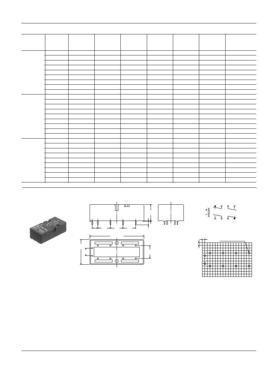
DIMENSIONS
1) SF2
12.7
.500
53.3
±
0.3
2.098
±
.012
12.7
.500
12.7
.500
5.08
.200
6
5
8
7
10
9
1
2
12
11
16
±
0.3
.630
±
.012
12.7
.500
3.5
±
0.3
.138
±
.012
0.5
.020
25.0
.984
7.62
.300
5
1
2
6
7
8
9
10
11
12
2.54
.100
2.54
.100
10-1.4 DIA. HOLES
10-.055 DIA. HOLES
General tolerance:
±
0.3
±.012
PC board pattern (Bottom view)
Tolerance:
±
0.1
± .004
Schematic (Bottom view)
mm
inch
260
SF
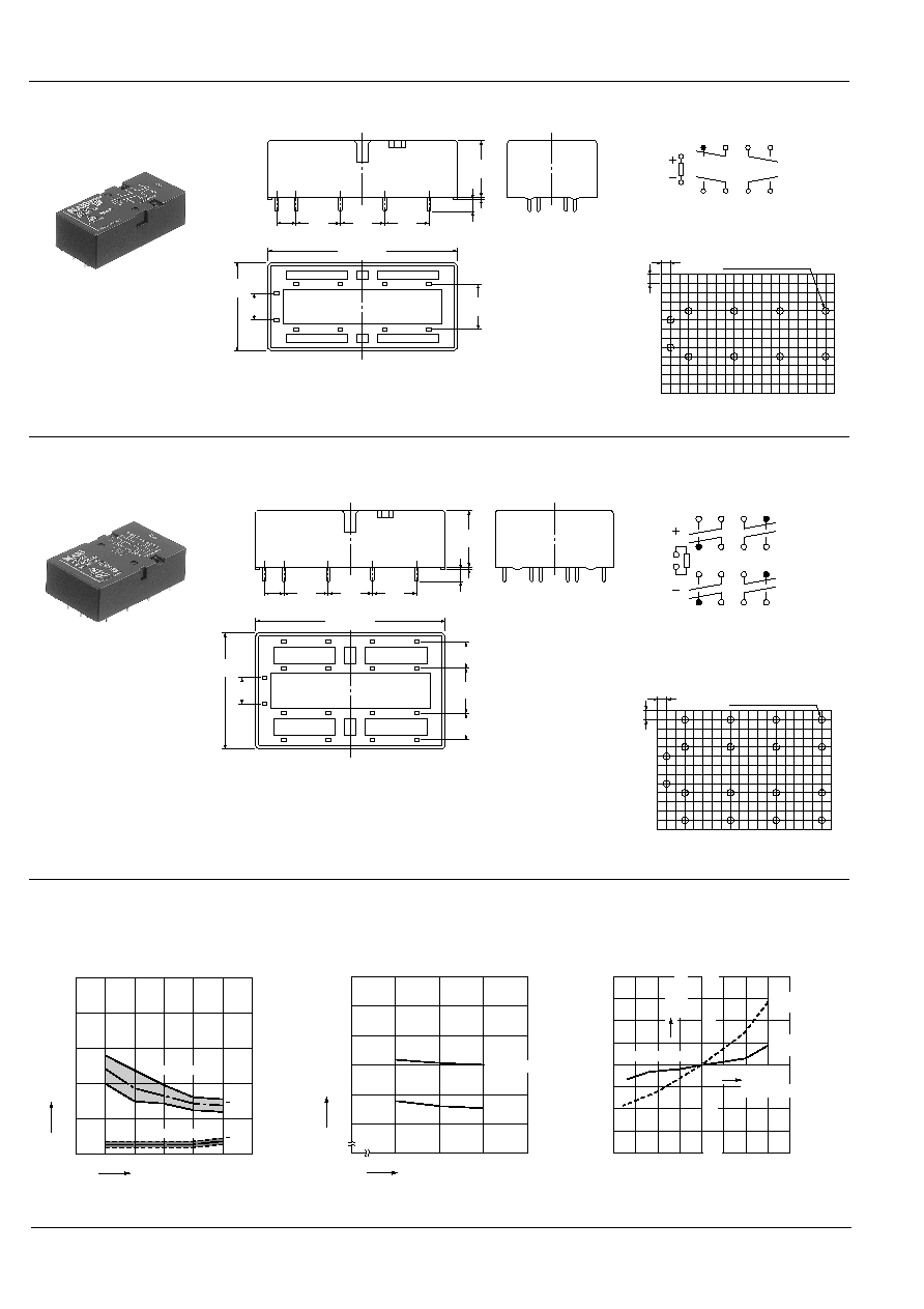
1. Operate/release time
2. Coil temperature rise
Coil applied voltage: 120%V
Contact switching current: 6A
3. Ambient temperature characteristics
Tested sample: SF4-DC12V
Quantity: n = 6
10
20
30
0
40
50
60
30
50
70
Temperature rise,
∞
C
Ambient temperature,
∞
C
Inside the coil
Contact
-40 -20
0
20 40
60
80
-50
100
50
-100
Rate of
change, %
Ambient
temperature,
∞
C
Pick-up
voltage
Drop-out
voltage
3) SF4
1
13
5
2
14
6
15
7
16
8
9
17
10
18
11
19
12
20
2.54
.100
2.54
.100
18-1.4 DIA. HOLES
18-.055 DIA. HOLES
General tolerance:
±
0.3
±.012
PC board pattern (Bottom view)
Schematic (Bottom view)
Tolerance:
±
0.1
±.004
12.7
.500
53.3
±
0.3
2.098
±
.012
12.7
.500
12.7
.500
5.08
.200
6
5
18
17
20
19
8
7
10
9
14
13
16
15
1
2
12
11
16
±
0.3
.630
±
.012
12.7
.500
7.62
.300
7.62
.300
3.5
±
0.3
.138
±
.012
0.3
.012
33
±
0.3
1.299
±
.012
7.62
.300
REFERENCE DATA
10
20
30
0
40
50
80
100
90
120
110
Min.
Max.
Operate time
Release time
Min.
Max.
x
x
Operate/release time, ms
Coil applied voltage, %V
2) SF3
12.7
.500
53.3
±
0.3
2.098
±
.012
12.7
.500
12.7
.500
5.08
.200
6
5
8
7
10
9
1
2
12
11
16
±
0.3
.630
±
.012
12.7
.500
3.5
±
0.3
.138
±
.012
0.5
.020
25.0
.984
7.62
.300
5
6
7
8
9
10
11
12
1
2
2.54
.100
2.54
.100
10-1.4 DIA. HOLES
10-.055 DIA. HOLES
General tolerance:
±
0.3
±.012
PC board pattern (Bottom view)
Schematic (Bottom view)
Tolerance:
±
0.1
±.004
mm
inch
261
SF
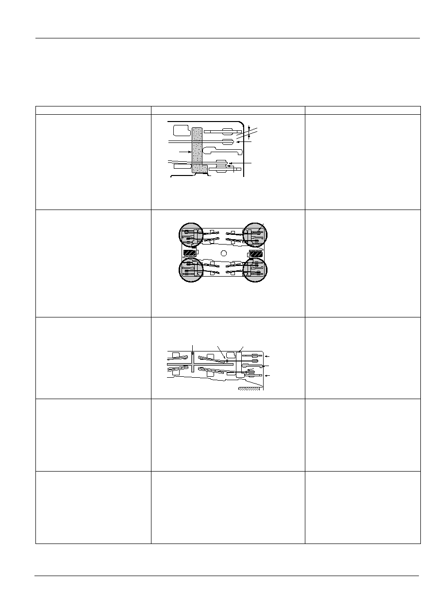
Structure
Operation
1. Forced operation method
(2a2b, 3a1b, 4a4b types)
The two contacts "a" and "b" are coupled with the same
card. The operation of each contact is regulated by the
movement of the other contact.
Even when one contact is welded closed,
the other maintains a gap of greater than
0.5 mm
.020 inch
.
In the diagram on the left, the lower
contact "b" have welded but the upper con-
tact "a" maintain at a gap of greater than
0.5 mm
.020 inch
.
Subsequent contact movement is
suspended and the weld can be detected
2. Independent operation method
(4a4b type)
None of four contacts are held in position by the armature.
Even though one of the external N.O. contacts has
welded, the other three contacts have returned owing to
the de-energizing of the coil.
Enables design of safety circuits that allow
weld detection and return at an early stage.
As shown at the top right of the diagram on
the left, if the external N.O. contact welds, a
0.5 mm
.020 inch
gap is maintained.
Each of the other contacts returns to N.O.
because the coil is no longer energized.
3. Separate chamber method
(2a2b, 3a1b, 4a4b types)
In independent chambers, the contacts "a" and "b" are
kept apart by a body/card separator or by the card itself.
Prevents shorting and fusing of springs and
spring failure owing to short-circuit current.
As shown on the diagram on the left, even
if the operating springs numbered 1 and 2
there is no shorting between "a" and "b"
contacts.
4. High-efficiency 4-gap balanced
armature structure
(2a2b, 3a1b, 4a4b types)
The use of high-efficiency magnetically polarized circuits
and 4-gap balanced armature structure means that
springs are not required.
Does away with return faults due to fatigue
or breakage of the return spring, especially
stoppage during contact states.
5. 2a2b contact
3a1b contact
4a4b contact
Structure with independent COM contact of (2a2b),
(3a1b), (4a4b) contacts.
Independent COM enables differing pole
circuit configurations. This makes it
possible to design various kinds of control
circuits and safety circuits.
Min. 0.5 mm
.020 inch
Contact a
Card
Weld
Contact b
Return
Return
External NO
contact weld
Return
Case separator
Card
Contact a
Body
separator
Contact b
1
2
SAFETY STRUCTURE OF SF RELAYS
This SF relay design ensures that
subsequent operations shut down and can
automatically return to a safe state when
the SF relay suffers overloading and other
circuit abnormalities (unforeseen
externally caused circuit or device
breakdowns, end of life incidents, and
noise, surge, and environmental
influences) owing to contact welding,
spring fusion or, in the worst-case
scenario, relay breakdown (coil rupture,
faulty operation, faulty return, and fatigue
and breakage of the operating spring and
return spring), and even in the event of
end of life.
262
SF
If the two form "a" contacts (Nos. 2 and 4) weld, the armature becomes non-operational and the gap between the two form "b"
contacts is maintained at greater than 0.5 mm
.020 inch
. Reliable isolation is thus ensured.
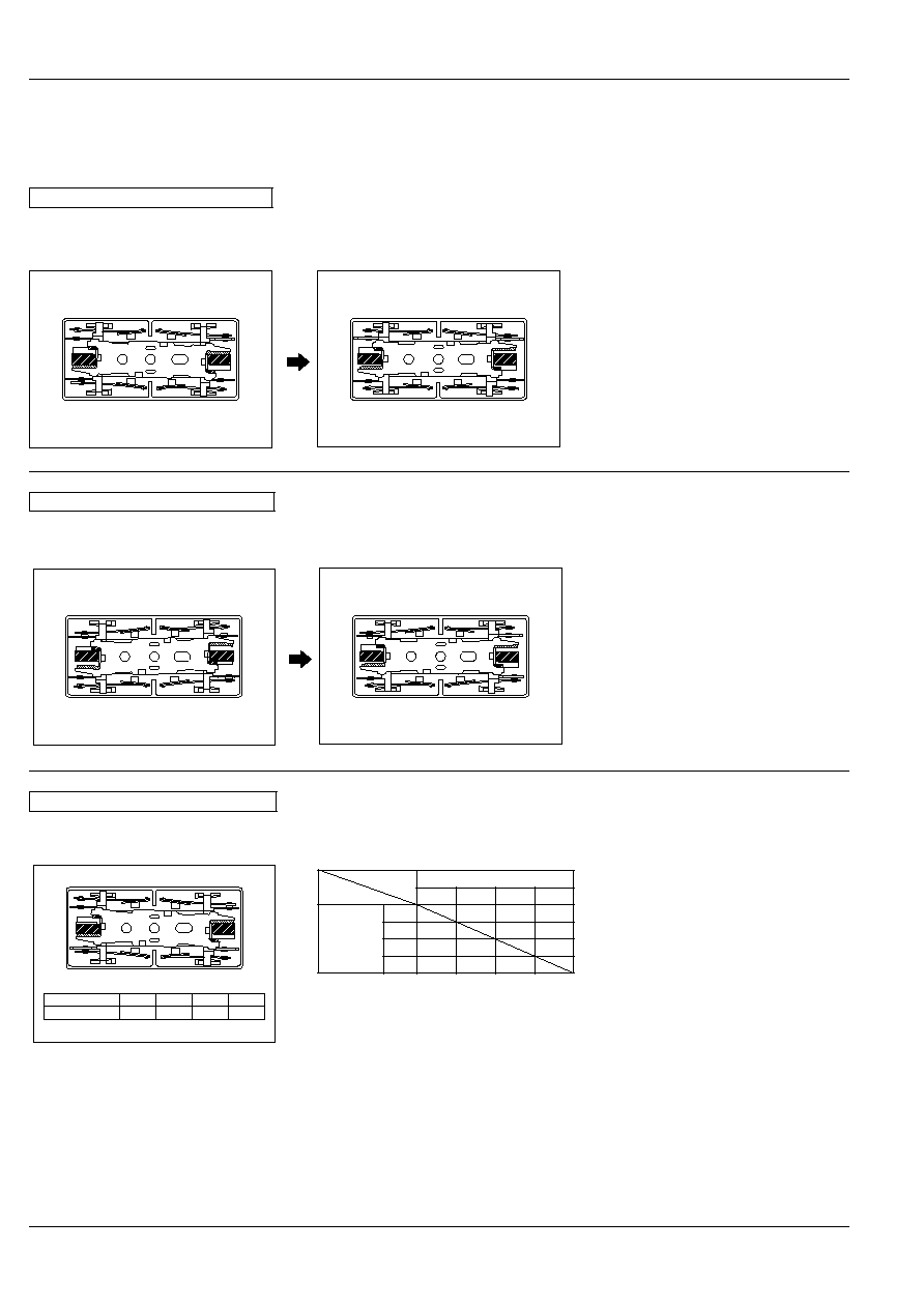
Form "a" Contact Weld
If the No. 2 contact welds.
Each of the two form "b" contacts (Nos. 1 and 3)
maintains a gap of greater than 0.5 mm
.020 inch
.
No.4
No.3
No.1
No.2
Energized
No.4
No.3
No.1
No.2
Non-energized (when no. 2 contact is welded)
No.4
No.3
No.1
No.2
Contact No.
No.1
No.2
No.3
No.4
Terminal No.
11≠12
7≠8
5≠6
9≠10
State of other contacts
1
2
3
4
Welded
terminal
No.
1
>0.5
>0.5
2
>0.5
>0.5
3
>0.5
>0.5
4
>0.5
>0.5
Note: Contact gaps are shown at the initial state.
If the contacts change state owing to loading/breaking
it is necessary to check the actual loading.
>0.5: contact gap is kept at min. 0.5 mm
.020 inch
Empty cells: either closed or open
Contact No.
Contact No.
The table below shows the state of the other contacts when the current through the welded form "a" contact is 0 V and the rated
voltage is applied through the form "b" contact.
Contact Operation Table
1) 2a2b Type
If the form "b" contacts (Nos. 1 and 3) weld, the armature becomes non-operational and the contact gap of the two form "a" contacts
is maintained at greater than 0.5 mm
.020 inch
. Reliable isolation is thus ensured.
Form "b" Contact Weld
If the No. 1 contact welds.
A gap of greater than 0.5 mm
.020 inch
is main-
tained at each of the two form "a" contacts (Nos.
2 and 4).
No.4
No.3
No.1
No.2
Non-energized
No.4
No.3
No.1
No.2
Energized (when no. 1 contact is welded)
THE OPERATION OF SF RELAYS (when contacts are welded)
SF relays work to maintain a normal operating state even when overloading or short-circuit currents occur. It is also easy to include
weld detection circuits and safety circuits in the design to ensure safety even if contacts weld.