 | –≠–ª–µ–∫—Ç—Ä–æ–Ω–Ω—ã–π –∫–æ–º–ø–æ–Ω–µ–Ω—Ç: D1723GF | –°–∫–∞—á–∞—Ç—å:  PDF PDF  ZIP ZIP |
Document Outline
- COVER
- FEATURES
- ORDERING INFORMATION
- FUNCTIONS
- RADIO FUNCTIONS
- PIN CONFIGURATION (Top View)
- PIN DESCRIPTIONS
- 1. KEY MATRIX CONFIGURATION
- 1.1 KEY MATRIX LAYOUT
- 1.2 SWITCH CONNECTION
- 1.3 KEY MATRIX CONNECTION
- 1.4 DESCRIPTION OF KEY MATRIX
- 2. MODE TRANSITION
- 2.1 WHEN INITIALIZE DIODE RDON = 1 (RADIO ON/OFF BY CE PIN)
- 2.2 RADIO ON/OFF BY RDSET SWITCH
- 2.3 DESCRIPTION OF EACH MODE
- 2.4 RADIO ON/OFF BY POWER KEY
- 3. DISPLAY
- 3.1 LCD PANEL
- 3.2 FONT
- 3.3 SEGMENT LINES
- 3.4 COMMON LINES
- 3.5 LCD ASSIGNMENT TABLE
- 3.6 DESCRIPTION OF DISPLAYS
- 4. RADIO MUTE OUTPUT TIMING (RDMUTE)
- 4.1 RADIO MUTE (RDMUTE# PIN) OUTPUT TIMING CHARTS
- 4.2 RADIO MUTE (RDMUTE# PIN) AND AUDIO MUTE (AMUTE# PIN) OUTPUT TIMING CHARTS
- 5. PIN I/O CIRCUITS
- 6. APPLICATION CIRCUITS
- 6.1 POWER ON/OFF (NO CLOCK DISPLAY AT POWER OFF) BY ALTERNATE SWITCH
- 6.2 POWER ON/OFF (CLOCK DISPLAY AT POWER OFF) BY ALTERNATE SWITCH
- 6.3 POWER ON/OFF (CLOCK DISPLAY AT POWER OFF) BY MOMENTARY SWITCH
- 7. ELECTRICAL SPECIFICATIONS
- 8. PACKAGE DIMENSION
- 9. RECOMMENDED SOLDERING CONDITIONS
MOS INTEGRATED CIRCUIT
µ
PD1723GF-013,
µ
PD1723GF-213
PLL FREQUENCY SYNTHESIZER AND CONTROLLER
FOR FM/MW/LF TUNER (CAR AUDIO)
Document No.
IC≠2772
(O.D.No. IC≠8187)
Date Published January 1991 P
Printed in Japan
The
µ
PD1723GF-013 and
µ
PD1723GF-213 are CMOS LSI developed for worldwide PLL frequency synthesizer
FM/MW/LW tuner use.
Their package is a 64-pin QFP. On-chip PLL frequency synthesizer, controller, 200 MHz prescaler, LCD driver,
and IF counter allow the construction of a compact FM/MW/LW tuner with a high-performance clock for high-
end car stereo and home stereo sets.
FEATURES
∑
Worldwide FM/MW banks and European LW band can be received.
∑
Abundant tuning functions, including manual tuning, autotuning (seek, scan), and preset memory scan
∑
Six buttons, independent preset memories for 18 FM stations (FM1, FM2, FM3; 6 stations each), 12 MW
stations (MW1, MW2; 6 stations each), 6 LW stations, and VF band
∑
FM: 3, MW: 2, LW: 1, VF: 1 last channel memories
∑
VF broadcast station (traffic information) autotuning (SK signal search) and DK standby function
∑
MONO (MONORAL) and LOC (LOCAL/DX) control output and display
∑
"ST" (STEREO) display
∑
MTL (METAL), NR
1
(NOISE REDUCTION), NR
2
, and AMS (AUTO MUSIC SEARCH) control output and display
∑
Auto preset memory function
∑
"
" (Compact Disk) display
∑
LOUD (LOUDNESS) control output and display
∑
12 hour and 24 hour clock display function (no clock display also possible)
∑
Single 5 V
±
10 % power supply
∑
On-chip prescaler (200 MHz max. V
in
= 0.3 V
P-P
), IF counter, LCD driver (1/2 duty, 1/2 bias drive, frame frequency
(100 Hz))
ORDERING INFORMATION
Order Code
Package
Quality Grade
µ
PD1723GF-011-3BE
64-pin plastic QFP (14x20)
Standard
µ
PD1723GF-211-3KE
64-pin plastic QFP (14x20)
Standard
DATA SHEET
Please refer to "Quality grade on NEC Semiconductor Devices" (Document number IEI-1209) published by NEC
Corporation to know the specification of quality grade on the devices and its recommended applications.
©
1991
2
µ
PD1723GF-013,
µ
PD1723GF-213
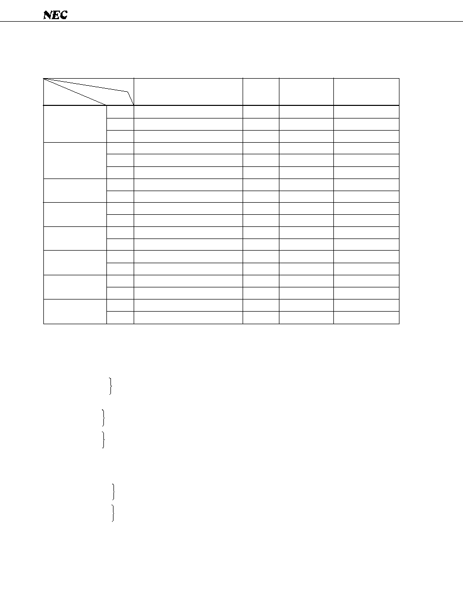
FUNCTIONS
Receiving frequency, channel spacing, reference frequency, intermediate frequency
Item
Area
Band
Receiving Frequency
Channel
Space
Reference
Frequency
Intermediate
Frequency
FM
MW
LW
FM
MW
LW
FM
MW
FM
MW
FM
MW
FM
MW
FM
MW
FM
MW
87.500 to 108.00 MHz
522 to 1620 kHz
144 to 290 kHz
87.500 to 108.000 MHz
522 to 1620 kHz
144 to 290 kHz
87.5 to 108.0 MHz
530 to 1620 kHz
87.5 to 107.9 MHz
630 to 1620 kHz
87.5 to 107.9 MHz
530 to 1710 kHz
87.5 to 108.0 MHz
531 to 1602 kHz
76.0 to 90.0 MHz
522 to 1629 kHz
87.5 to 108.0 MHz
520 to 1620 kHz
50 kHz
9 kHz
1 kHz
50 kHz
9 kHz
1 kHz
100 kHz
10 kHz
200 kHz
10 kHz
200 kHz
10 kHz
100 kHz
9 kHz
100 kHz
9 kHz
100 kHz
5 kHz
25 kHz
9 kHz
1 kHz
25 kHz
9 kHz
1 kHz
25 kHz
10 kHz
25 kHz
10 kHz
25 kHz
10 kHz
25 kHz
9 kHz
25 kHz
9 kHz
25 kHz
5 kHz
10.7 MHz
450 kHz
450 kHz
10.7 MHz
459 kHz
459 kHz
10.7 MHz
450 kHz
10.7 MHz
450 kHz
10.7 MHz
450 kHz
10.7 MHz
450 kHz
≠10.7 MHz
450 kHz
10.7 MHz
450 kHz
Europe 1
Europe 2
United States 1
United States 2
United States 3
Australia and
Middle East
Japan
Central and
South America
RADIO FUNCTIONS
(1) Manual tuning
Manual up
Manual down
(2) Autotuning
Seek up
Seek down
Scan up
Scan down
(3) Preset memory scan
(4) VF autotuning
SK seek up
SK seek down
SK scan up
SK scan down
............. Step and fast
............. When a broadcast station is detected that frequency is held.
............. Broadcast station is received every 5 seconds.
............. Contents of independent FM, MW and LW preset memories are received
every 5 seconds.
............. When an SK signal is detected, that frequency is held.
............. Broadcast station with SK signal is received every 5 seconds.

3
µ
PD1723GF-013,
µ
PD1723GF-213
(5) Preset memory
FM band .......... FM1: 6 stations, FM2: 6 stations, FM3: 6 stations
MW band ........ MW1: 6 stations, MW2: 6 stations
LW band .......... 6 stations
VF band ........... 6 stations
When the LW band is used, MW2 cannot be used.
(6) Last preset memory ........ FM1, FM2, FM3, MW1, MW2, LW and VF; 1 station each
(7) LOC (LOCAL) control output and display (Auto Local Function selection possible)
(8) FM MONO (MONORAL) control output and display (VF band is same as FM)
(9) "ST" (STEREO) display ....... Effective at FM and VF
(10) Auto preset memory
(11) DK standby and SK alarm functions
TAPE FUNCTIONS
(1) Tape direction display ......... Flashes at 2 MHz at fast forward.
(2) AMS (AUTO MUSIC SEARCH) control output and display
(3) MTL (METAL) control output and display
(4) NR
1
(NOISE REDUCTION) and NR
2
control output and display
CLOCK FUNCTIONS
(1) 12 hour clock display (with "AM" and "PM" display) or 24 hour clock display selectable
(2) Colon (" : ") flashing (1 Hz) selectable
(3) In non-clock mode, low consumption current (10
µ
A max.) backup possible
OTHERS
(1) LOUD (LOUDNESS) control output and display ......... Common in radio, tape, and CD modes
(2) Key acknowledge (BEEP) output (2.25 kHz, 40 ms) ........ Output by effective momentary key
(3) Display switching and priority display functions
(4) "
" (compact disk) display
(4) "
" (compact disk) display

4
µ
PD1723GF-013,
µ
PD1723GF-213
PIN CONFIGURATION (Top View)
33
34
35
36
37
38
39
40
41
42
43
44
45
46
47
48
49
50
51
19
18
17
16
15
14
13
12
11
10
9
8
7
6
5
4
3
2
1
32 31 30 29 28 27 26 25 24 23 22 21 20
52 53 54 55 56 57 58 59 60 61 62 63 64
LCD
LCD
LCD
LCD
LCD
LCD
LCD
LCD /KS
LCD /KS
LCD /KS
LCD /KS
LCD /KS
LCD /KS
LCD /KS
LCD /KS
LCD /KS
LCD /KS
LCD /KS
LCD /KS
22
21
20
19
18
17
16
15
14
13
12
11
10
9
8
7
6
5
4
15
14
13
12
11
10
9
8
7
6
5
4
LOUD (PA )
MONO/NR (PA )
FMIF (PA )
AMIF (PA )
AMUTE (PC )
RDMUTE (PC )
BAND (PC )
BAND (PC )
MODE (PD )
LOC (PD )
AGCC (PD )
V
CE
FM (VCOH)
AM (VCOL)
V
EO
EO
NC
3
2
0
3
2
1
0
3
2
1
DD2
DD1
2
1
2
1
2
1
LCD
LCD
LCD
LCD
LCD
BEEP (CGP)
GND
XI
XO
POWER (PB )
NR (PB )
MTL (PB )
AMS (PB )
23
24
25
26
27
2
3
2
1
0
LCD /KS
LCD /KS
LCD /KS
LCD /KS
COM
COM
GND
K
K
K
K
SD (AD)
ST (INT)
3
2
1
0
1
2
1
3
2
1
0
3
2
1
0
1

5
µ
PD1723GF-013,
µ
PD1723GF-213
PIN DESCRIPTIONS
OUTPUT
TYPE
This pin is not connected to the internal chip. There-
fore, leave it open or connect it to GND, V
DD
, etc.
PLL (Phase Locked Loop) error output pins.
When the frequency obtained by dividing the local
oscillation frequency (VCO output) is higher than the
reference frequency, High level is output from these
pins. When it is lower than the reference frequency,
Low level is output from these pins. When the two fre-
quencies are the same, these pins are floated.
This output is input to an external LPF (Low Pass Filter)
and is applied to a varactor diode through the LPF. EO
1
and EO
2
output the same waveform so that the pin to
be used can be freely selected. When the radio is OFF,
these pins are floated.
Device power supply input pin.
This pin supplies 5 V
±
10 % power voltage during
device operation (radio, tape, and CD modes). When
the diode matrix NOCLK switch is 1 (shorted by diode),
when the CE pin (pin 7) is made Low level, this pin
drops to 2.5 V and data hold is enabled. When a voltage
of 0
4.5 V is supplied to this pin, the data is initialized.
Supply 0
4.5 V to this pin within 500 ms.
Always connect pins 4 and 8 to the same potential. V
DD1
(pin 4) is the analog system (PLL, A/D converter, INT,
CE) power supply and V
DD2
(pin 8) is the digital system
(CPU, LCD driver, IF counter) power supply.
The AM (MW and LW band) local oscillation output
(VCO output) is input to this pin. When the radio is
turned on and the MW or LW band is received, this pin
becomes active. Otherwise, it is pulled down
internally.
The input amplitude is 0.3 V
P-P
MIN.
Since there is an on-chip AC amplifier, block the DC
component with a capacitor.
DESCRIPTION
PIN NAME
SYMBOL
PIN No.
AM
AM local
oscillation
input
5
No
connection
NC
1
2
3
EO
1
EO
2
4
8
Power
supply input
V
DD1
V
DD2
--
CMOS
3-state
--
Input
Error out