 | –≠–ª–µ–∫—Ç—Ä–æ–Ω–Ω—ã–π –∫–æ–º–ø–æ–Ω–µ–Ω—Ç: EF2-3T | –°–∫–∞—á–∞—Ç—å:  PDF PDF  ZIP ZIP |
Document Outline
- ˛ˇ
- ˛ˇ
- ˛ˇ
- ˛ˇ
- ˛ˇ
- ˛ˇ
- ˛ˇ
- ˛ˇ
- ˛ˇ
- ˛ˇ
- ˛ˇ
- ˛ˇ
- ˛ˇ
- ˛ˇ
- ˛ˇ
- ˛ˇ
- ˛ˇ
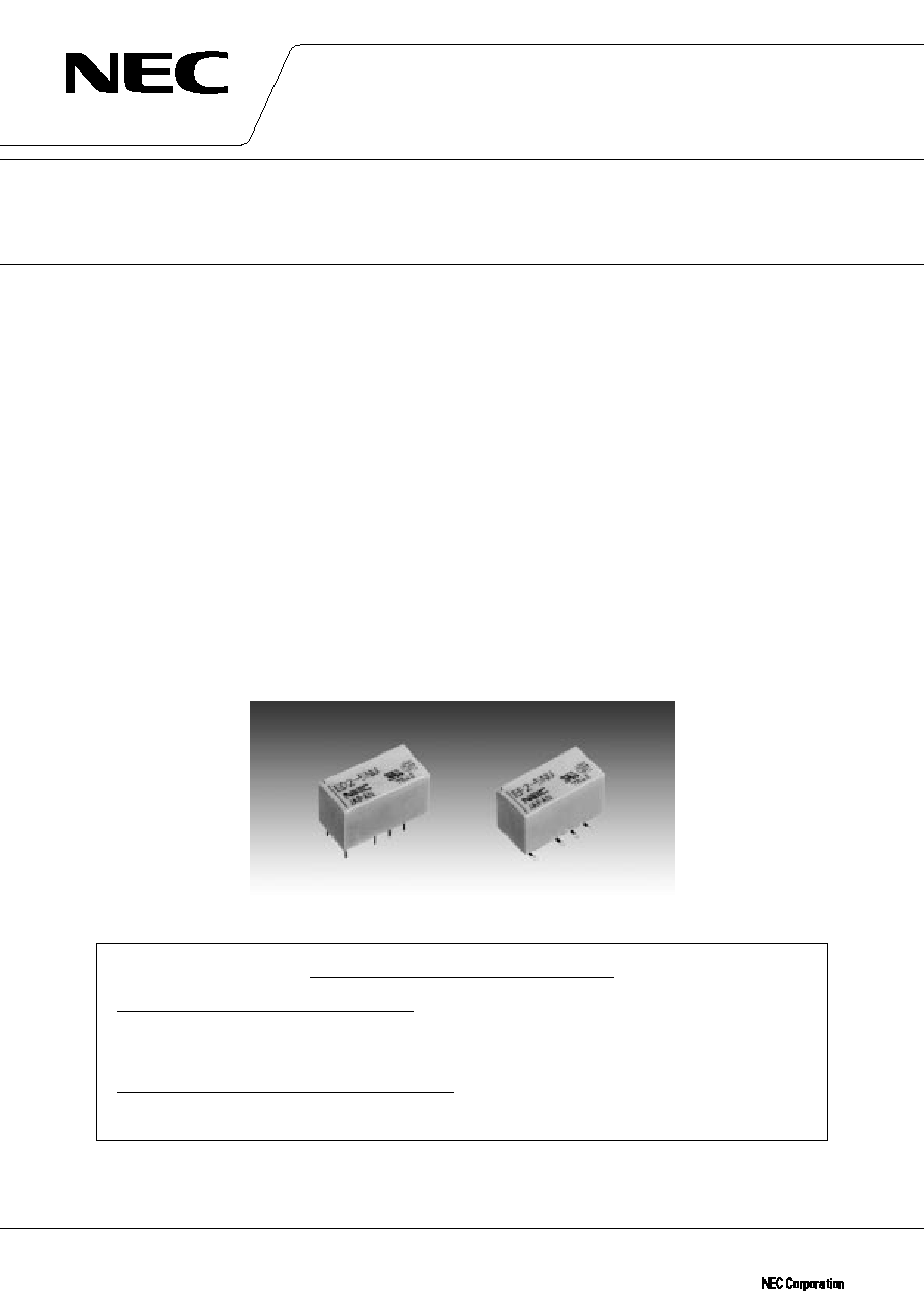
DATA S H E E T
ED2/EF2 SERIES
MINIATURE SIGNAL RELAY
Ultra-low power, compact and lightweight, High breakdown voltage,
Surface mounting type
DESCRIPTION
NEC's new miniature signal relays, ED2/EF2 series, achieved 50 mW of ultra low power consumption.
FEATURES
TM Low power consumption (50 mW)
TM Applicable for the surge voltage standard of FCC (1500 V, 10
◊
160
µ
s) and BELLCORE (2500 V, 2
◊
10
µ
s)
TM Two types for through-hole mounting (ED2 series) and surface mounting (EF2 series)
TM Variation of dense mounting type and/or long-joint-life type for latest SMT
∑ Compatible configuration and terminal allocation with dense mounting type of EE2 series
∑ Upgraded soldering joint reliability between the relay terminal and PCB by optimization of the terminal
configuration;
20-year-joint-life under 35∞C-per-day-temperature-difference specified in IPC-SM-785 for telecommuication
equipment
APPLICATIONS
Electronic switching systems, PBX, terminal equipment, telephone system, instrumental equipment.
For Right Use of Miniature Relays
DO NOT EXCEED MAXIMUM RATINGS.
Do not use relays under exceeding conditions such as over ambient temperature, over voltage
and over current. Incorrect use could result in abnormal heating, damage to related parts or
cause burning.
READ CAUTIONS IN THE SELECTION GUIDE.
Read the cautions described in NEC's "Miniature Relays" (ER0046EJ
) when you choose relays
for your application.
Document No. ER0304EJ2V0DS00 (2nd edition)
Date Published February 1999 M
Printed in Japan
The information in this document is subject to change without notice.
©
1997

ED2/EF2 SERIES
DATA SHEET ER0304EJ2V0DS00
2
DIMENSIONS AND PAD LAYOUTS (Unit : mm (inch))
ED2 SERIES
Note. General tolerance :
±
0.2 (
±
0.008)
Dimensions in show basic size.
NJ type : Leads-2.8 mm (0.110)
Note. General tolerance :
±
0.1 (
±
0.004)
4
◊
2.54 (0.100)
2
◊
2.54(0.1)
2.54(0.1)
8 - 0.8 (0.031)
5
◊
2.54 (0.100)
2
◊
2.54(0.100)
2.54(0.100)
2.54
(0.100)
2.54
(0.100)
10- 0.8 (0.031)
Non-latch and Single coil latch
Double coil latch
(Bottom fiew)
7.5 (0.30) MAX.
9.4(0.37) MAX.
3.2
(0.13)
5.08
0.25
(0.01)
0.5
(0.02)
15.0 (0.59) MAX.
5.08 2.54 2.54 2.54
(0.20)(0.10)(0.10)(0.10)
(0.20)
EF2 SERIES
15.0 MAX.
(0.591)
15.0 MAX.
(0.591)
EF2-..
EF2-..NU
EF2-..NUX
EF2-..NUN
EF2-..NUH
7.5 MAX.
(0.296)
15.0 MAX.
(0.591)
7.5 MAX.
(0.296)
15.0 MAX.
(0.591)
7.5 MAX.
(0.296)
7.5 MAX.
(0.296)
1.0
(0.039)
10.0 MAX.
(0.394)
1.0
(0.039)
10.0 MAX.
(0.394)
1.6
(0.063)
10.6 MAX.
(0.418)
1.35
(0.053)
10.35 MAX.
(0.408)
2-2.54
(2-0.100)
2-2.54
(2-0.100)
5.08
(0.200)
note2
note2
note2
2-2.54
(2-0.100)
5.08
(0.200)
2-2.54
(2-0.100)
5.08
(0.200)
Note 1. General torelance :
±
0.2 (
±
0.008)
Note 2. This pair of pins at the right end applies
to double coil latch type only.
note2
5.08
(0.200)
9.5
(0.374)
5.08
(0.200)
5.08
(0.2)
9.0
(0.354)
7.5
(0.295)
5.08
(0.200)
5.08
(0.200)
7.5
(0.295)
Note 1. General torelance :
±
0.1 (
±
0.004)
Note 2. This pair of pads at the right end
applies to double coil latch type only.
Type
A
B
EF2-..
3.0 (0.118)
7.29 (0.287)
EF2-..NU
3.0 (0.118)
7.29 (0.287)
EF2-..NUX
2.73 (0.107)
7.02 (0.276)
EF2-..NUH
2.0 (0.079)
6.29 (0.248)
EF2-..NUN
2.0 (0.079)
6.29 (0.248)
1.0(0.039)
note2
note2
B
A
5.08
(0.200)
3-2.54
(0.100)
(Bottom view)
ED2/EF2 SERIES
3
DATA SHEET ER0304EJ2V0DS00
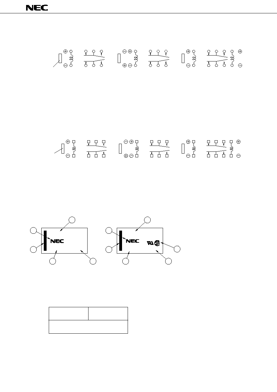
PIN CONFIGURATIONS (bottom view)
ED2 SERIES
Index mark of
relay direction
Non-latch type
(not energized position)
Single coil latch type
(reset position)
Double coil latch type
(reset position)
S : Coil polarity of set (operate)
R : Coil polarity of reset (release)
1
3
4
5
6
12
10
9
8
7
1
3
4
5
12
10
9
8
1
3
4
5
12
10
9
S
R
S
R
8
1
3
4
5
12
10
9
8
R
Index mark of
relay direction
1
3
4
5
12
10
9
8
6
7
1
3
4
5
12
10
9
8
S
R
S
Non-latch type
(not energized position)
Single coil latch type
(reset position)
Double coil latch type
(reset position)
S : Coil polarity of set (operate)
R : Coil polarity of reset (release)
EF2 SERIES
ED2-5NU
9717
JAPAN
JAPAN
1
4
3
6
5
2
ED2-5
9717
1
4
3
5
2
q Part number
w Manufacturer
e Country of origin
r Date code
t Index mark of relay direction
(pin No. 1, 12)
y UL, CSA Marking
Standard type
UL recognized,
CSA certified type (Under application for latch type)
MARKINGS (top view)
UL Recognized
CSA Certificated
(UL508)*
(CSA C22.2 No14)
File No E73266
File No LR46266
30 Vdc, 1 A
(Resistive)
110 Vdc, 0.3 A (Resistive)
125 Vac, 0.5 A (Resistive)
* Spacing : UL114, UL478
SAFETY STANDARD AND RATING
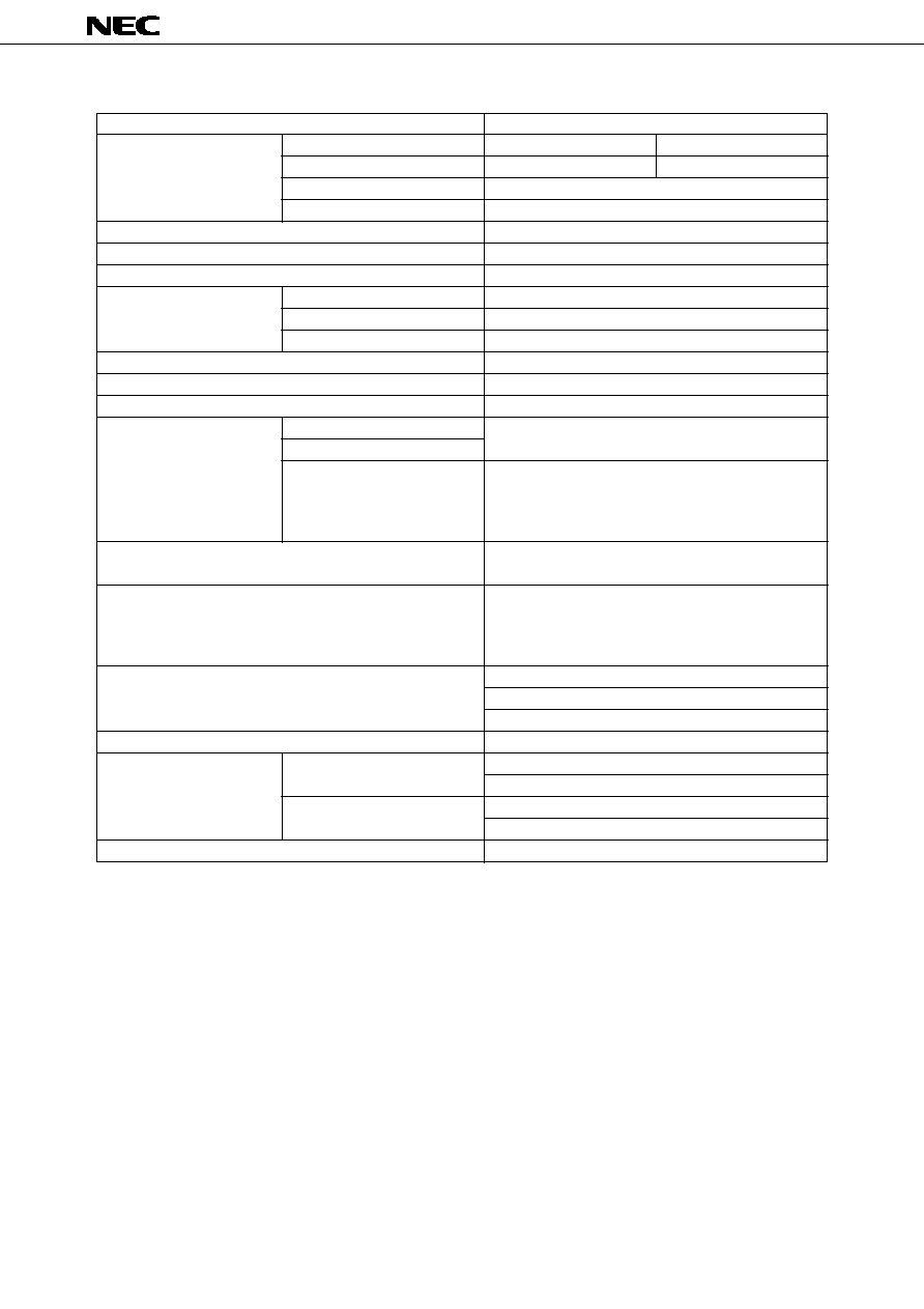
ED2/EF2 SERIES
DATA SHEET ER0304EJ2V0DS00
4
2 Form c
30 W (resistive)
62.5 VA (resistive)
220 Vdc
250 Vac
1 A
2 A
10 mV.dc, 10
µ
A *
4
50 m
typ. (Initial)
Silver alloy with gold alloy overlay
50 to 70 mW
30 to 80 mW
50 to 80 mW
Approximately 3 ms
Approximately 2 ms without diode
1000 M
at 500 Vdc
1000 Vac for one minute (1500 V surge, 10
◊
160
µ
s
1
)
Non-latch type and single-coil latch type
1500 Vac for one minute (2500 V surge, 2
◊
10
µ
s *
2
)
Double-coil latch type
1000 Vac for one minute (1500 V surge, 10
◊
160
µ
s *
1
)
735 m / s
2
(75 G) (misoperating)
980 m / s
2
(100 G) (destructive failure)
10 to 55 Hz at double amplitude of 3 mm (20 G)
(misoperating)
10 to 55 Hz, double amplitude of 5 mm (30 G)
(Destructive failure)
Non-latch type (Additional "N"): ≠40 to +85∞C
Non-latch type (Standard): ≠40 to +70∞C
Latch type : ≠40 to +70∞C
7 degrees at nominal coil voltage (50 mW)
1
◊
10
8
*
3
operations (Non-latch type)
1
◊
10
7
operations (Latch type)
50 Vdc 0.1 A (resistive), 1
◊
10
6
operations at 70∞C
10 Vdc 10 mA (resistive), 1
◊
10
6
operations at 70∞C
Approximately 2.2 grams
Nominal Operating Power
Contact Form
Maximum Switching Power
Maximum Switching Voltage
Maximum Switching Current
Maximum Carrying Current
Minimum Contact Ratings
Initial Contact Resistance
Contact Material
Non-Latch Type
Single Coil Latch Type
Double Latch Type
Operate Time (Excluding Bounce)
Release Time (Excluding Bounce)
Insulation Resistance
Between Open Contacts
Breakdown Voltage
Between Adjacent Contacts
Between Coil and Contact
Shock Resistance
Vibration Resistance
Ambient Temperature
Coil Temperature Rise
No-load
Load
Weight
PERFORMANCE CHARACTERISTICS (Community)
Running specifications
1
rise time : 10
µ
s, fall time : 160
µ
s
2
rise time : 2
µ
s, fall time : 10
µ
s
3
This shows a number of operation where it can be running by which a fatal is not caused, and number of operation by wich
a stesdy characteristic is maintained is 1
◊
10
7
times.
4
This value is a reference value in the resistive load.
Minimum capacity changes depending on seitching frequency and enviroment temperature and the load.
Contact Ratings
ED2/EF2 SERIES
5
DATA SHEET ER0304EJ2V0DS00
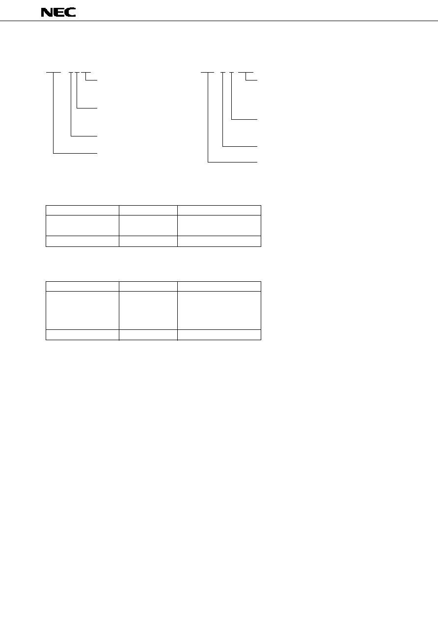
PART NUMBER SYSTEM
EF2 - 5 S NUH
Latch type
Nil : Non-latch type (Note 2)
S
: Single coil latch type
T
: Double coil latch type
Nominal coil voltage
1.5, 3, 4.5, 5, 6, 9, 12, 24 volts
EF2 series
Feature
Nil
: Standard type
NU
: UL recognized, CSA certified type
NUX : High solder joint reliability (20 years)
NUH : Minimum footprint (7.5
◊
15)
NUN : High solder joint reliability with minimum footprint
E D 2 ≠ 9 S NU
Nil : Standard type
NU : UL recognized, CSA certified type
NJ : Trimed leads
(UL recognized, CSA certified type)
Latch type
Nil : Non-latch type (Note 1)
S : Single coil latch type
T : Double coil latch type
Nominal coil voltage
1.5, 3, 4.5, 5, 6, 9, 12, 24 V
ED2 series
(UL, CSA : Under application for latch type)
Additional "N" type
Standard type
Part Number
ED2-*NU
-*NJ
ED2-
Must Operate Voltage
75%
80%
Note 1. There are two specification in operate voltage of Non-latch type relay.
: Nominal coil voltage
Additional "N" type
Standard type
Part Number
ED2-*NU
-*NUX
-*NUH
-*NUN
EF2-
Must Operate Voltage
75%
80%
Note 2. There are two specification in operate voltage of Non-latch type relay.
: Nominal coil voltage
ED2/EF2 SERIES
DATA SHEET ER0304EJ2V0DS00
6
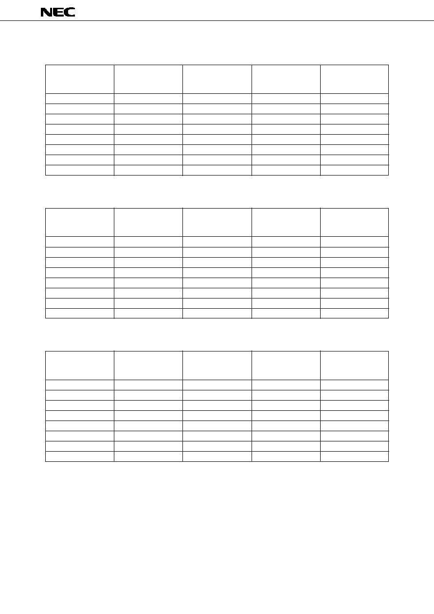
NOMINAL LINEUP (Community)
Non-latch Type (Standard)
Nominal Coil
Voltage
(Vdc)
1.5
3
4.5
5
6
9
12
24
Coil
Resistance
(
)
±
10 %
45
180
405
500
720
1473
2400
8229
Must Operate
Voltage
(Vdc)
1.2
2.4
3.6
4
4.8
7.2
9.6
19.2
Must Release
Voltage
(Vdc)
0.15
0.3
0.45
0.5
0.6
0.9
1.2
2.4
at 20∞C
Nominal
operate power
(mW)
50
50
50
50
50
55
60
70
Single-Coil Latch Type
Nominal Coil
Voltage
(Vdc)
1.5
3
4.5
5
6
9
12
24
Coil
Resistance
(
)
±
10 %
75
300
675
833
1200
2700
4800
7200
Must Operate
Voltage
(Vdc)
1.2
2.4
3.6
4
4.8
7.2
9.6
19.2
Must Release
Voltage
(Vdc)
1.2
2.4
3.6
4
4.8
7.2
9.6
19.2
at 20∞C
Nominal
operate power
(mW)
30
30
30
30
30
30
30
80
Non-latch Type (Additional "N")
Nominal Coil
Voltage
(Vdc)
1.5
3
4.5
5
6
9
12
24
Coil
Resistance
(
)
±
10 %
45
180
405
500
720
1473
2400
8229
Must Operate
Voltage
(Vdc)
1.13
2.25
3.38
3.75
4.5
6.75
9
18
Must Release
Voltage
(Vdc)
0.15
0.3
0.45
0.5
0.6
0.9
1.2
2.4
at 20∞C
Nominal
operate power
(mW)
50
50
50
50
50
55
60
70
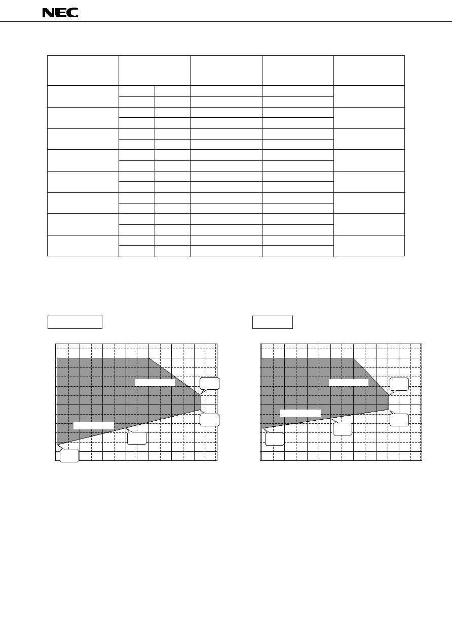
ED2/EF2 SERIES
7
DATA SHEET ER0304EJ2V0DS00
Coil
Resistance
(
)
±
10 %
S
45
R
45
S
180
R
180
S
405
R
405
S
500
R
500
S
720
R
720
S
1620
R
1620
S
2880
R
2880
S
7200
R
7200
Must Operate
Voltage
(Vdc)
1.2
≠
2.4
≠
3.6
≠
4
≠
4.8
≠
7.2
≠
9.6
≠
19.2
≠
Must Release
Voltage
(Vdc)
≠
1.2
≠
2.4
≠
3.6
≠
4
≠
4.8
≠
7.2
≠
9.6
≠
19.2
Nominal Coil
Voltage
(Vdc)
1.5
3
4.5
5
6
9
12
24
Double-Coil Latch Type
Nominal
operate power
(mW)
50
50
50
50
50
50
50
80
at 20∞C
Ambient temperature (∞C)
A ratio of nominal coil voltage (%)
50
≠ 40
≠ 40
≠ 40% / 45 deg
+ 20% / 65 deg
0
20
40
60
80
60
70
80
90
100
150
110%
95%
57%
75%
Ambient temperature (∞C)
A ratio of nominal coil voltage (%)
50
≠ 40
≠ 40
≠ 40% / 30 deg
+10% / 50 deg
0
20
40
60
80
60
70
80
90
100
150
110%
95%
73%
85%
Non latch typ
(Additional "N")
Recommended coil voltage with ambient temperature
Latch typ

ED2/EF2 SERIES
DATA SHEET ER0304EJ2V0DS00
8
q Coil Temperature Rise
q Operate Time
q Contact Resistance
q Switching Capacity
q Breakdown Voltage
q Release Time without diode
q Release Time with diode
q Transfer Time
20
15
10
5
0
50
100
150
200
Applied Power(mW) at 20∞C
Coil Temperature Rise(deg)
99.99
99.9
99
95
90
80
60
40
20
10
5
1
0.1
0.01
Cumulative Distribution(%)
Breakdown Voltage(KV,AC)
Between
adjacent
contacts
Between coil
and contacts
Between open
contacts
1
2
3
4
5
4
2
0
50
100
150
200
250
Bounce Time at Operate
Operate Time
Applied Power(mW)
Operate Time or
Bounce Time at Operate(ms)
2
1
0
50
100
150
200
Applied Power(mW)
Release Time
Bounce Time at Release
Release Time or
Bounce Time at Release(ms)
Cumulative Distribution(%)
Make contact
Break contact
0
10
20
30
40 50
60
70 80
90 100
99.99
99.9
99
95
90
80
60
40
20
10
5
1
0.1
0.01
Contact Resistance(m
)
4
2
0
50
100
150
200
Applied power(mW)
Release Time
Bounce Time at Release
Release Time or
Bounce Time at Release(ms)
2.0
1.0
0.5
0.4
0.3
0.2
30
100
200
DC Load
(resistive)
AC Load
(resistive)
Switching Voltage(V)
Switching Capacity(A)
99.99
99.9
99
95
90
80
60
40
20
10
5
1
0.1
0.01
Cumulative Distribution(%)
Transfer Time(ms)
At operate
At release
0
0.2 0.4 0.6 0.8
1
1.2 1.4 1.6 1.8
2
TYPICAL PERFORMANCE DATA
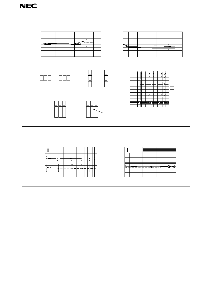
ED2/EF2 SERIES
9
DATA SHEET ER0304EJ2V0DS00
q Magnetic Interference (ED2 Relay)
q Mechanical Life
ON
ON
I
I
Drift of Operate Voltage(%)
II
III
IV
V
VI
ON
ON
Layout
Layout V
Sample
Layout VI
II
Layout
Layout
40
30
20
10
0
-10
-20
-30
-40
III
Layout
IV
Layout
OFF
OFF
OFF
OFF
OFF
OFF
ON
ON
ON
OFF
,
,
,
,
,
,
Max.
Min.
I
Drift of Release Voltage(%)
II
III
IV
V
VI
Layout
Mounting Layout mm(inch)
40
30
20
10
0
-10
-20
-30
-40
Max.
Min.
2.54 (0.1)
5
4
3
2
1
0
1
2
3
4
10
at 70∞C, 50 operation/sec
Operate Voltage
Release Voltage
Operate Voltage or
Release Voltage(V)
Number of Operations(x10
5
operations)
1000
500
300
200
100
50
30
20
10
1
0
2
3
5
10
at 70∞C, 50 operations/sec
Make contact
Break contact
Contact Resistance(m
)
Number of Operations(x10
5
operations)
ED2/EF2 SERIES
DATA SHEET ER0304EJ2V0DS00
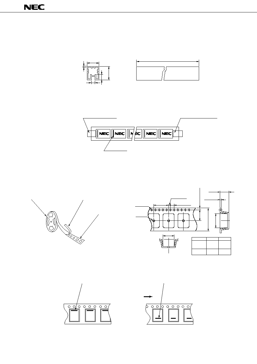
10
Reel
Top cover tape
Embossed carrying tape
APPEARANCE
TAPE DIMENSION mm (inch)
2.0(0.079)
0.4
(0.016)
A
4.0(0.157)
11.5
(0.453)
1.75(0.069)
24.0(0.945)
15.5
(0.610)
1.5
(0.054)
2.2
(0.087)
16.0(0.63)
B
A
B
EF2-
Max.10.9
10.0
EF2-
NU
(0.429)
(0.394)
EF2-
NUX
EF2-
NUH Max.11.1
8.0
EF2-
NUN
(0.437)
(0.315)
Relay orientation mark and tape carrying direction.
Orientation mark
Orientation mark
Tape carrying direction
L
EF2-***-L
Carrying tape type
Part number
R
EF2-****-R
Rubber stopper (Red)
Rubber stopper (Green)
Index Mark
543
±
1
11.9
±
0.3
15.5
±
0.3
(2.4)
(4.8)
(0.5 t)
( ) Reference
Outline of Package
Dimension of Package (Unit : mm)
35 pieces / Tube
Material : Polyvinyl chloride
(anti-static treated)
TUBE PACKAGE (ED2, EF2)
TAPE PACKAGE (EF2)
ED2/EF2 SERIES
11
DATA SHEET ER0304EJ2V0DS00
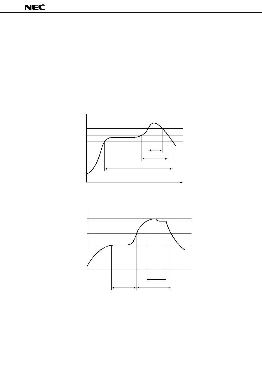
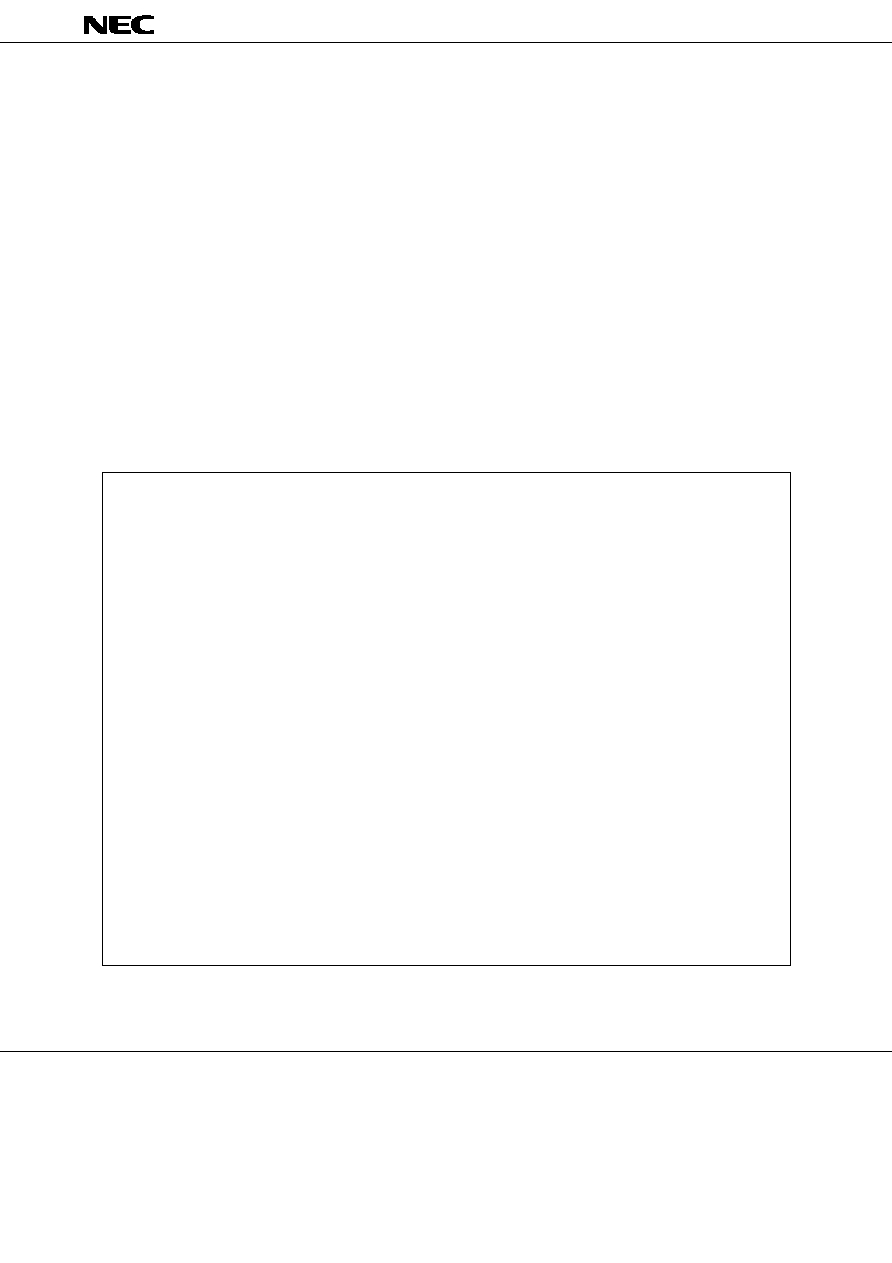
SOLDERING TEMPERATURE CONDITION
Through≠hole mounting type (ED2)
q Automatic soldering
* Preheating
: 100
∞
C max. 1 minute max.
* Solder temperature : 250
∞
C max.
* Solder time
: 10 seconds max.
w Manual soldering
* Solder temperature : 350
∞
C max.
* Solder time
: 3 seconds max.
Surface mounting type (EF2)
Time
Time
T max.; 215
T max.; 235
200 max.
Temperature (∞C)
165 max.
100 max.
200
IRS Method
VPS Method
Note:
1. Temperature profile shows printed circuit board surface temperature on the relay terminal portion.
2. Check the actual soldering condition to use other method except above mentioned temperature profiles.
175
150
Temperature (∞C)
60 sec. max.
90 sec. max.
60 sec.
200 sec.
80 sec.
30 sec.

ED2/EF2 SERIES
DATA SHEET ER0304EJ2V0DS00
12
GUIDE TO APPLICATIONS
1. When connecting coils, refer to the pin configuration to prevent misoperation or malfunction.
2. The latch type relay should be initialized at the appointed position (set or reset position) when using, and should
be energized or deenergized to the specified polarity to avoid wrong operations by reversed contact state.
3. Ultrasonic cleaning is not recommended to keep contact performance reliable. Alcohol based solvents are
available as proper solvents.
4. Pressurized stress on the relay cover may affect reliable operation.
5. Minimum contact load of the relay is 10 mVdc, 10
µ
A.
This value is a reference value in the resistance load.
Minimum capacity changes depending on switching frequency and environment temperature and the load.

ED2/EF2 SERIES
13
DATA SHEET ER0304EJ2V0DS00

ED2/EF2 SERIES
DATA SHEET ER0304EJ2V0DS00
14

ED2/EF2 SERIES
15
DATA SHEET ER0304EJ2V0DS00
ED2/EF2 SERIES
No part of this document may be copied or reproduced in any form or by any means without the prior
written consent of NEC Corporation. NEC Corporation assumes no responsibility for any errors which
may appear in this document.
NEC Corporation does not assume any liability for infringement of patents, copyrights or other intellec-
tual property rights of third parties by or arising from use of a device described herein or any other
liability arising from use of such device. No license, either express, implied or otherwise, is granted
under any patents, copyrights or other intellectual property rights of NEC Corporation or others.
While NEC Corporation has been making continuous effort to enhance the reliability of its electronic
components, the possibility of defects cannot be eliminated entirely. To minimize risks of damage or
injury to persons or property arising from a defect in an NEC electronic component, customers must
incorporate sufficient safety measures in its design, such as redundancy, fire-containment, and anti-
failure features.
NEC devices are classified into the following three quality grades:
"Standard", "Special", and "Specific". The Specific quality grade applies only to devices developed based
on a customer designated "quality assurance program" for a specific application. The recommended
applications of a device depend on its quality grade, as indicated below. Customers must check the
quality grade of each device before using it in a particular application.
Standard: Computers, office equipment, communications equipment, test and measurement equipment, au-
dio and visual equipment, home electronic appliances, machine tools, personal electronic equip-
ment and industrial robots
Special:
Transportation equipment (automobiles, trains, ships, etc.), traffic control systems, anti-disaster
systems, anti-crime systems, safety equipment and medical equipment (not specifically de-
signed for life support)
Specific: Aircrafts, aerospace equipment, submersible repeaters, nuclear reactor control systems, life
support systems or medical equipment for life support, etc.
The quality grade of NEC devices is "Standard" unless otherwise specified in NEC's Data Sheets or Data Books.
If customers intend to use NEC devices for applications other than those specified for Standard quality grade,
they should contact an NEC sales representative in advance.
Anti-radioactive design is not implemented in this product.