 | –≠–ª–µ–∫—Ç—Ä–æ–Ω–Ω—ã–π –∫–æ–º–ø–æ–Ω–µ–Ω—Ç: EP2-4L2T | –°–∫–∞—á–∞—Ç—å:  PDF PDF  ZIP ZIP |
AUTOMOTIVE RELAYS
Twin Relays EN2/EP2 Series
Single Relays EP1/MR301 Series
JC≠13003D (5th edition)
August 1995 M
Printed in Japan
©
1992
2
DESCRIPTION
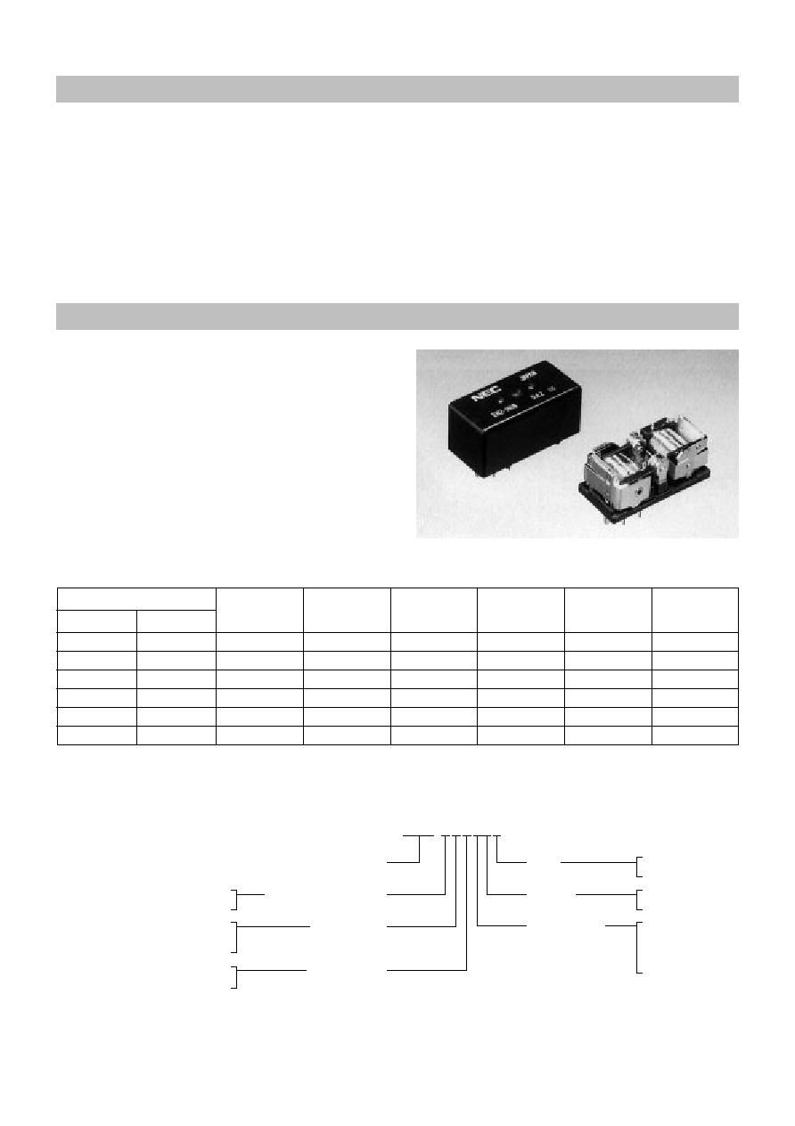
EN2 Series
The EN2, EP2, EPI and MR301 series power relays can meet the requirements of high quality and reliability in automotive
eIectronics applications.
The EN2 and EP2 series are the twin relays which have two units in one package and smaller than conventional two relays.
These relays are divided into two types for different usage. One is H bridge type and the other is separate type.
The EN2 series is suitable for heavy load applications (35 A max.). The EP2 series is designed for medium load applications
(25 A max.). The EP1 and MR301 series are the 1C contact form relays.
Many of these relays have been used in automotive electronics applications throughout the world.
FEATURES
q
Twin relay for motor and solenoid reversible control
q
30% Iess relay space than conventional two relays
q
Contact switching current of 35 A max.
q
High performance and productivity by unique
symmetrical structure
q
Flux tight housing
q
Delivered in stick-tube for automatic insertion machine
q
Washable type available
PART NUMBERS AND COIL RATINGS
Nominal
Coil
Nominal
Must
Must
Nominal
Voltage
Resistance
Current
Operate Voltage Release Voltage
Operate Power
(Vdc)
(
±
10%)
(mA)
(Vdc max.)
(Vdc min.)
(W)
12
125
96.0
6.5
0.6
1.15
12
125
96.0
7.0
0.6
1.15
12
180
67.0
7.5
0.6
0.8
12
180
67.0
8.0
0.6
0.8
12
250
53.0
8.0
0.9
0.64
12
250
53.0
8.5
0.9
0.64
Part Numbers
H Bridge Type Separate Type
EN2-1N1S
EN2-1N1ST
EN2-1N2S
EN2-1N2ST
EN2-2N3S
EN2-2N3ST
EN2-2N4S
EN2-2N4ST
EN2-3N4S
EN2-3N4ST
EN2-3N5S
EN2-3N5ST
at 25∞C (77∞F)
s PART NUMBER SYSTEM
E N 2 - B 1 N 1 S T
Wiring
Type
Enclosure
Carrying Current Capacity
Contact Material
Operate Voltage
(at 25
∞
C)
Coil Resistance
(at 25
∞
C)
Nil : H bridge type
T : Sparate type
Nil : Unsealed
S : Ssaled
1 : 6.5 V max.
2 : 7.0 V max.
3 : 7.5 V max.
4 : 8.0 V max.
5 : 8.5 V max.
Nil
: Standard type
B : High current type
1 : 125
±
10%
2 : 180
±
10%
3 : 225
±
10%
N : Silver oxide complex alloy type I
H : Silver oxide complex alloy type II

3
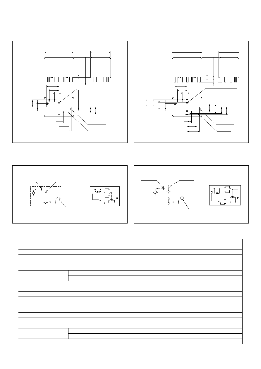
s DIMENSIONS
mm (inch)
[H Bridge Type]
[Separate (T) Type]
s PCB PAD LAYOUT and SCHEMATICS
(bottom view) mm (inch)
[H Bridge Type]
[Separate (T) Type]
33.0
±
0.5
(1.3)
2-0.5
◊
1.1
2-1.3
◊
1.3 (0.02
◊
0.05)
4- 0.6 ( 0.02)
(0.02
◊
0.04)
5.75
10.75
14.1
(0.23)
5.75
(0.23)
10.75
(0.42)
14.1
(0.56)
(0.42)
(0.56)
16.0
±
0.5
(0.63)
16.0
±
0.5
2.7
5.45
5.45
(0.21)
6.4
(0.11)
2.7
(0.11)
3.1
(0.12)
(0.21)
(0.25)
0.6(0.02)
35
(0.63)
(0.14)
33.0
±
0.5
(1.3)
4-0.5
◊
1.1 (0.02
◊
0.04)
2-1.3
◊
1.3 (0.02
◊
0.05)
4- 0.6 ( 0.02)
5.75
10.75
14.1
(0.23)
5.75
(0.23)
10.75
14.1
(0.42)
(0.56)
(0.42)
(0.56)
16.0
±
0.5
(0.63)
16.0
±
0.5
2.7
5.45
5.45
6.4
(0.25)
(0.21)
6.4
(0.11)
3.1
(0.12)
2.7
(0.11)
3.1
(0.12)
(0.21)
(0.25)
0.6(0.02)
35
(0.63)
(0.14)
5
6
7
2
1
4
8
3
2- 1.5
+0.1
≠ 0
( 0.059)
( 0.075)
2- 1.9
+0.1
≠ 0
4- 1.1
+0.1
≠ 0
( 0.043)
(Side A)
(Side B)
2
(Unit A)
(Unit B)
1
4
9
5
10
6
7
8
3
4- 1.5
+0.1
≠ 0
( 0.059)
( 0.075)
2- 1.9
+0.1
≠ 0
4- 1.1
+0.1
≠ 0
( 0.043)
Items
Contact Form
Contact Material
Contact Resistance
Contact Switching Voltage
Contact Switching Current
Contact Carrying Current
Standard
High
Operate Time
Release Time
Nominal Operate Power
Insulation Resistance
Breakdown Voltage
Shock Resistance
Vibration Resistance
Ambient Temperature
Coil Temperature Rise
Life Expectancy
Mechanical
Electrical
Weight
Specification
1 form C
◊
2 [H Bridge Type & Separate Type]
Silver oxide complex alloy (Special types available)
50 m
max. (measured at 7 A) initial
30 Vdc max.
5 Vdc min.
35 A max. (at 16 Vdc)
1 A min.
25 A max. (2 minutes max.) (at 12 Vdc, 85∞C)
35 A max. (2 minutes max.) (at 12 Vdc, 85∞C}
Approx. 5 ms max. (at 12 Vdc, excluding bounce) initial
Approx. 2 ms max. (at 12 Vdc, excluding bounce) initial, without diode
0.64 W/0.8 W/1.15 W (at 12 Vdc)
100 M
min. (at 500 Vdc) initial
500 Vdc min. (for 1 minute) initial
98 m/s
2
[Approx. 10 G] min. (misoperating)
10 to 300 Hz, 43 m/s
2
[Approx. 4.4 G] min. (misoperating)
≠40∞C to +85∞C (≠40∞F to +185 ∞F)
50∞C/W (contact carrying current 0 A)
1 x 10
6
operations
1 x 10
5
operations (at 14 Vdc, Motor Load 25 A/7 A)
Approx. 18 gr.
SPECIFICATIONS
at 25∞C (77∞F)
4
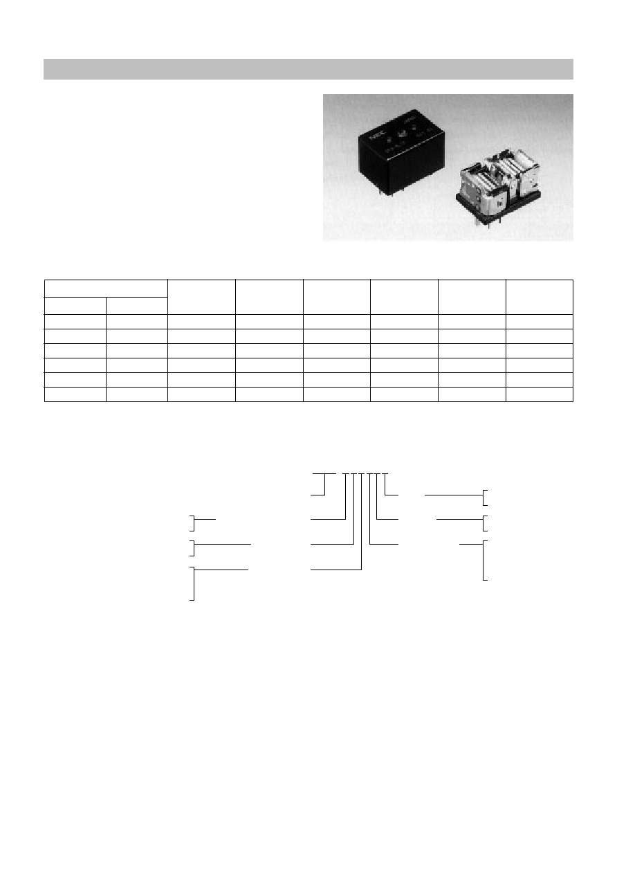
EP2 Series
FEATURES
q
Twin relay for motor and solenoid reversible control
q
50% Iess relay space than conventional two relays
q
Contact switching current of 25 A max.
q
High performance and productivity by unique
symmetrical structure
q
Flux tight housing
q
Delivered in stick-tube for automatic insertion machine
q
Washable type available
PART NUMBERS AND COIL RATINGS
Nominal
Coil
Nominal
Must
Must
Nominal
Voltage
Resistance
Current
Operate Voltage Release Voltage
Operate Power
(Vdc)
(
±
10%)
(mA)
(Vdc max.)
(Vdc min.)
(W)
12
225
53.3
6.5
0.9
0.64
12
225
53.3
7.0
0.9
0.64
12
225
53.3
7.5
0.9
0.64
12
300
40.0
7.5
0.9
0.48
12
300
40.0
8.0
0.9
0.48
12
300
40.0
8.5
0.9
0.48
Part Numbers
H Bridge Type Separate Type
EP2-3N1S
EP2-3N1ST
EP2-3N2S
EP2-3N2ST
EP2-3N3S
EP2-3N3ST
EP2-4N3S
EP2-4N3ST
EP2-4N4S
EP2-4N4ST
EP2-4N5S
EP2-4N5ST
at 25∞C (77∞F)
s PART NUMBER SYSTEM
E P 2 - B 3 L 1 S T
Wiring
Type
Enclosure
Carrying Current Capacity
Contact Material
Operate Voltage
(at 25
∞
C)
Coil Resistance
(at 25
∞
C)
Nil : H bridge type
T : Sparate type
Nil : Unsealed
S : Ssaled
1 : 6.5 V max.
2 : 7.0 V max.
3 : 7.5 V max.
4 : 8.0 V max.
5 : 8.5 V max.
Nil
: Standard type
B : High current type
3 : 225
±
10%
4 : 300
±
10%
L : Silver oxide complex alloy type I
N : Silver oxide complex alloy type II
G : Silver oxide complex alloy
(High current type)
5
s DIMENSIONS
mm (inch)
[H Bridge Type]
[Separate (T) Type]
s PCB PAD LAYOUT and SCHEMATICS
(bottom view) mm (inch)
[H Bridge Type]
[Separate (T) Type]
Items
Contact Form
Contact Material
Contact Resistance
Contact Switching Voltage
Contact Switching Current
Contact Carrying Current
Standard
High
Operate Time
Release Time
Nominal Operate Power
Insulation Resistance
Breakdown Voltage
Shock Resistance
Vibration Resistance
Ambient Temperature
Coil Temperature Rise
Life Expectancy
Mechanical
Electrical
Weight
Specification
1 form C
◊
2 [H Bridge Type & Separate Type]
Silver oxide complex alloy (Special types available)
50 m
max. (measured at 7 A) initial
30 Vdc max.
5 Vdc min.
25 A max. (at 16 Vdc)
1 A min.
20 A max. (2 minutes max.) (at 12 Vdc, 85∞C)
25 A max. (2 minutes max.) (at 12 Vdc, 85∞C)
Approx. 5 ms max. (at 12 Vdc, excluding bounce) initial
Approx. 2 ms max. (at 12 Vdc, excluding bounce) initial, without diode
0.48 W/0.64 W (at 12 Vdc)
100 M
min. (at 500 Vdc) initial
500 Vdc min. (for 1 minute) initial
98 m/s
2
[Approx. 10 G] min. (misoperating)
10 to 300 Hz, 43 m/s
2
[Approx. 4.4 G] min. (misoperating)
≠40∞C to +85∞C (≠40∞ F to +185∞F)
50∞C/ W (contact carrying current 0 A)
1 x 10
6
operations
1 x 10
5
operations (at 14 Vdc, Motor Load 20 A/3 A)
Approx. 15 gr.
SPECIFICATIONS
at 25∞C (77∞F)
2-1.3
◊
1.3
2-0.5
◊
1.1 (0.02
◊
0.04)
4- 0.6
( 0.02)
(0.05
◊
0.05)
3.5
8.0
(0.31)
10.1
(0.4)
(0.14)
(0.14) 3.5
8.0
(0.31)
10.1
(0.4)
16.2
±
0.5
(0.64)
23.8
±
0.5
(0.94)
16.0
±
0.5
2.2(0.09)
3.1(0.12)
5.45
(0.21)
6.4
(0.25)
2.2
(0.09)
5.45
(0.21)
0.5(0.02)
35
(0.63)
(0.14)
2-1.3
◊
1.3
4-0.5
◊
1.1 (0.02
◊
0.04)
4- 0.6
( 0.02)
(0.05
◊
0.05)
3.5
8.0
(0.31)
10.1
(0.4)
(0.14)
(0.14) 3.5
8.0
(0.31)
10.1
(0.4)
16.2
±
0.5
(0.64)
23.8
±
0.5
(0.94)
16.0
±
0.5
2.2 (0.09)
3.1(0.12)
5.45
(0.21)
6.4
(0.25)
2.2
3.1
(0.09)
(0.12)
5.45
(0.21)
6.4
(0.25)
0.5(0.02)
35
(0.63)
(0.14)
8
7
6
5
4
3
2
1
( 0.075)
2- 1.9
+0.1
≠ 0
( 0.059)
2- 1.5
+0.1
≠ 0
( 0.043)
4- 1.1
+0.1
≠ 0
(Side A)
(Side B)
2
3 9
4
6
6
10
7
8
1
( 0.075)
2- 1.9
+0.1
≠ 0
( 0.059)
4- 1.5
+0.1
≠ 0
( 0.043)
4- 1.1
+0.1
≠ 0
(Unit A)
(Unit B)