DATA S H E E T
EP2F/EP1F SERIES
AUTOMOTIVE RELAYS
HIGH HEAT RESISTIVITY
Document No. ER0145EJ1V0DS00
Date Published December 1995 M
Printed in Japan
1995
DESCRIPTION
The NEC EP2F / EP1F series are PC-board mount type automotive relays suitable for various motor controls
and other applications that require a high level of quality and performance.
The operate temperature range for EP2F / EP1F series is ≠40∞C through +125∞C.
By this high heat resistivity, the contact carrying current of EP2F / EP1F series at 25∞C increases 1.3 or 1.4 times
compared with that of EP2 / EP1 series.
FEATURES
TM Operating ambient temperature up to +125∞C (EP2 / EP1 : +85∞C)
TM Suitable for motor and solenoid reversible control
TM High performance and productivity by unique structure
TM Flux tight housing
APPLICATIONS
TM Power window control
TM Power sunroof
TM Wiper system
©
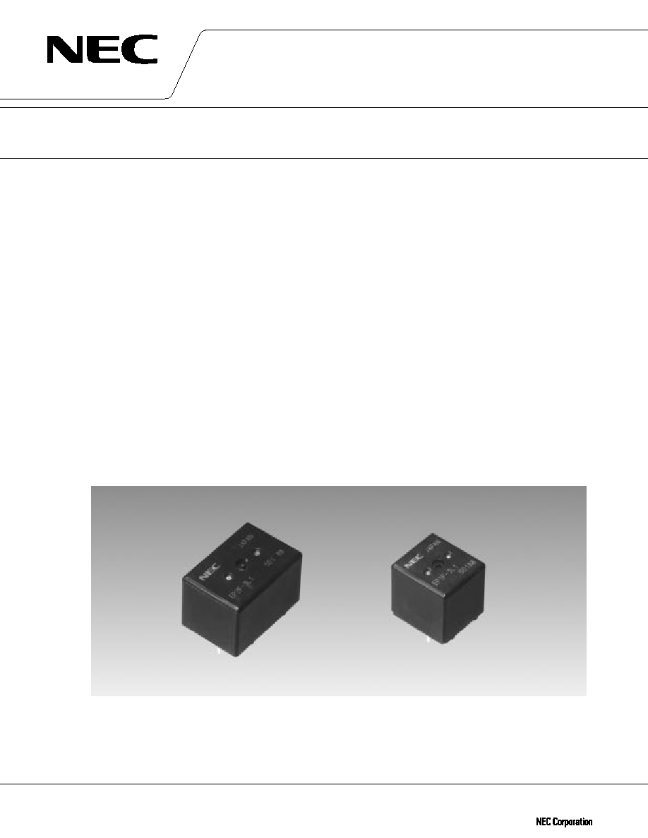
EP2F SERIES
EP1F SERIES

4
EP2F / EP1F SERIES
SPECIFICATIONS
Items
Contact Form
Contact Material
Contact Resistance
Contact Switching Voltage
Contact Switching Current
Contact Carrying Current
Operate Time
Release Time
Normal Operate Power
Insulation Resistance
Breakdown Voltage
Shock Resistance
Vibration Resistance
Ambient Temperature
Coil Temperature Rise
Life Expectancy
Weight
EP2F
EP1F
1 form C
◊
2 (H bridg type and separate type)
1 form C
Silver oxide complex alloy
50 m
max. (measured at 7 A) initial
16 Vdc max.
25 A max.
35 A (2 minutes max. 12 Vdc at 25∞C)
40 A (2 minutes max. 12 Vdc at 25∞C)
30 A (2 minutes max. 12 Vdc at 85∞C)
35 A (2 minutes max. 12 Vdc at 85∞C)
25 A (2 minutes max. 12 Vdc at 125∞C)
30 A (2 minutes max. 12 Vdc at 125∞C)
Approx. 5 ms (at 12 Vdc excluding bounce) initial
Approx. 2 ms (at 12 Vdc excluding bounce) initial
0.64 W (at 12 Vdc)
100 M
min. (at 500 Vdc) initial
500 Vdc min. (for 1 minute) initial
98 m / s
2
[Approx. 10 G] min. (misoperating)
10 to 300 Hz, 43 m / s
2
[Approx. 4.4 G] min. (misoperating)
≠40 ∞C to +125 ∞C (≠40 ∞F to +257 ∞F)
50 ∞C / W (without contact carrying current)
1
◊
10
6
operations
1
◊
10
5
operations (at 14 Vdc, Motor Load 25 A / 7 A) at 25 ∞C
1
◊
10
5
operations (at 14 Vdc, Motor Load 18 A / 5 A) at 125 ∞C
1
◊
10
5
operations (at 14 Vdc, Motor Load 20 A / 3 A) at 25 ∞C
1
◊
10
5
operations (at 14 Vdc, Motor Load 12 A / 2 A) at 125 ∞C
Approx. 15 gr
Approx. 8 gr
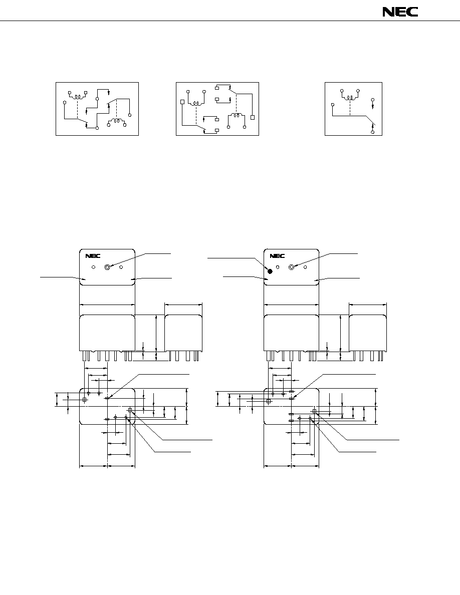
Mechanical
Electrical
Contact
G
Contact
L or N
COIL RATING
EP2F SERIES
EP1F SERIES
Contact
G
Contact
L or N
Part Number
H Bridge Type
Separate Type
EP2F-B3G1
EP2F-B3G1T
EP2F-B3G2
EP2F-B3G2T
EP2F-B3G3
EP2F-B3G3T
EP2F-B3L1
EP2F-B3L1T
EP2F-B3L2
EP2F-B3L2T
EP2F-B3L3
EP2F-B3L3T
Nominal
Voltage
(Vdc)
12
12
12
12
12
12
Coil
Resistance
(
10 %)
225
225
225
225
225
225
Must
Operate Voltage
(Vdc max.)
605
7.0
7.5
6.5
7.0
7.5
Must
Release Voltage
(Vdc min.)
0.9
0.9
0.9
0.9
0.9
0.9
Nominal
Operate Power
(W)
0.64
0.64
0.64
0.64
0.64
0.64
Contact
G
Contact
L or N
Part Number
EP1F-B3G1
EP1F-B3G2
EP1F-B3G3
EP1F-B3L1
EP1F-B3L2
EP1F-B3L3
Nominal
Voltage
(Vdc)
12
12
12
12
12
12
Coil
Resistance
(
10 %)
225
225
225
225
225
225
Must
Operate Voltage
(Vdc max.)
6.5
7.0
7.5
6.5
7.0
7.5
Must
Release Voltage
(Vdc min.)
0.9
0.9
0.9
0.9
0.9
0.9
Nominal
Operate Power
(W)
0.64
0.64
0.64
0.64
0.64
0.64
at 25 ∞C (77 ∞F)
at 25 ∞C (77 ∞F)
+
≠
+
≠
5
EP2F / EP1F SERIES
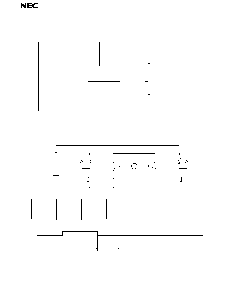
NUMBERING SYSTEM
Tr1
Tr2
100 ms min.
It is necessary to take more than 100 msec intervals for on / off timing between driving Tr1 and Tr2. If the interval
is less than 100 msec, an excessive current happen to flow to the relay contacts.
E P 2 F
≠
B
3
L
1
S
T
Wiring
Nil : H Bridge Type
T : Separate Type
Enclosure
Nil : Unsealed (Standard type)
T : Sealed
Operate Voltage
(at 25∞C)
1 : 6.5 V max.
2 : 7.0 V max.
3 : 7.5 V max.
Contact Material
L, N : Silver oxide complex alloy, type I
G : Silver oxide complex alloy, type II
Type
EP2F
EP1F
MOTOR
Tr1
Tr2
STOP
off
off
FORWARD
on
off
REVERSE
off
on
TYPICAL APPLICATION (H Bridge Type)
M
Tr1
Tr2
16 V