The information in this document is subject to change without notice.
AUTOMOTIVE RELAYS
ET2/ET1 SERIES
1998
©
Document No. ER0429EJ1V0DS00
Date Published May 1999 P
Printed in Japan
DATA SHEET
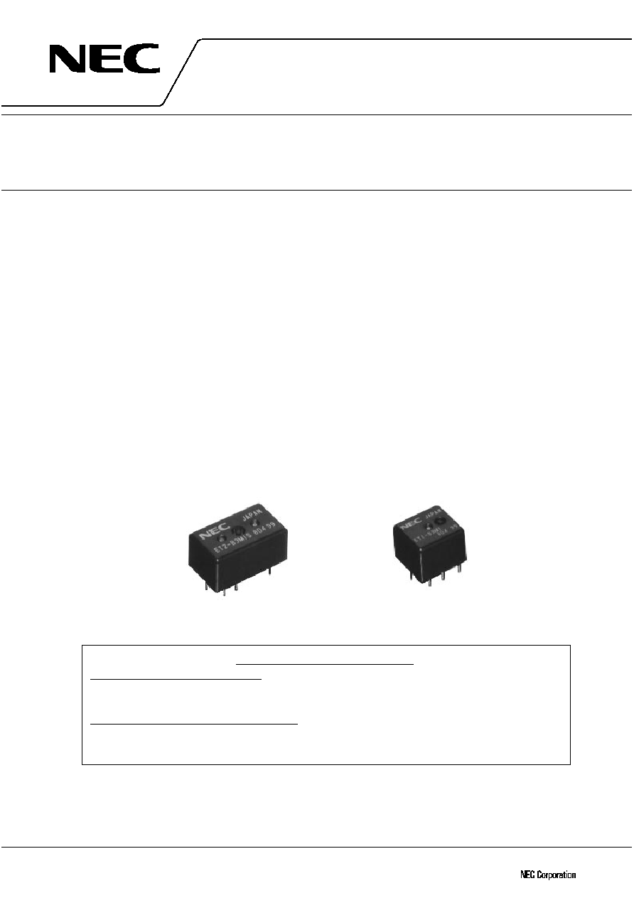
DESCRIPTION
The new NEC ET2/ET1 series is PC-board mount type automotive relay suitable for various motor and heater
control applications that require a high quality and performance. The ET2/ET1 series is the relay that succeeds
fundamental structure and performance of the NEC EP2/EP1 series that has the high share with a motor control
usage of the automobile of the world. Besides the ET2/ET1 series is succeeding in about 50% of miniaturization in
comparison with the EP2/EP1 series.
FEATURES
∑
PC board mounting
∑
Approx. 50% relay volume of EP2/EP1
∑
Approx. 75% relay space of EP2/EP1
∑
Approx. 70% relay height of EP2/EP1
∑
Approx. 50% relay weight of EP2/EP1
APPLICATIONS
∑
Motor control
∑
Heater control
∑
Solenoid control
Type ET2
Type ET1
For Proper Use of Miniature Relays
DO NOT EXCEED MAXIMUM RATING.
Do not use relay under excessive conditions such as over ambient temperature, over voltage and over
current. Incorrect use could result in abnormal heating and damage to the relay or other parts.
READ CAUTIONS IN THE SELECTION GUIDE.
Read the cautions described in NEC's "Miniature Relays" (ER0046EJ
) before dose designing your relay
applications.
3
ET2/ET1 SERIES
Data Sheet ER0429EJ1V0DS00
SPECIFICATIONS
(at 20
∞
C)
Twin
Single
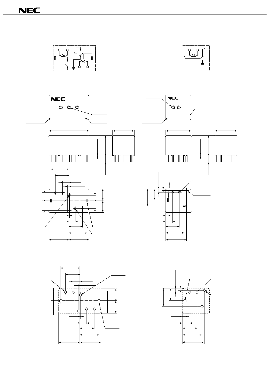
ET2-B3M1/ET2-B3M1S
ET1-B3M1/ET1-B3M1S
Contact Form
1 Form c
◊
2 (H Bridge)
1 Form c
Max. Switching Voltage
16 V dc
Max. Switching Current
25 A (at 16 Vdc)
Min. Switching Current
1 A (at 5 Vdc)
Contact Rating
Contact Resistance
4 m
typical (measured at 7 A) Initial
Contact Material
Silver oxide complex alloy
Operate Time (Excluding Bounce)
2.5 ms typical (at Nominal Voltage) Initial
Release Time (Excluding Bounce)
3 ms typical (at Nominal Voltage, with diode) Initial
Nominal Operate Power
640 mW
Insulation Resistance
100 M
at 500 V dc
Between Open Contact
500 V ac min. (for 1 minute)
Breakdown Voltage
Between Coil and Contact
500 V ac min. (for 1 minute)
Misoperation
98 m/s
2
(10 G)
Shock Resistance
Destructive Failure
980 m/s
2
(100 G)
Misoperation
10
300 Hz, 43 m/s
2
(4.4 G)
Vibration Resistance
Destructive Failure
10
500 Hz, 43 m/s
2
(4.4 G) 200 hour
Ambient Temperature
-
40 to +85
∞
C (
-
40 to +185
∞
F)
Coil Temperature Rise
70
∞
C (158
∞
F)/W
Mechanical
1
◊
10
6
operations
Power Window Motor
(14 V, 20 A, Locked)
100
◊
10
3
operations
Life
Expectancy
Electrical
Power Window Motor
(14 V, 20 A /3 A, Unlocked)
100
◊
10
3
operations
Weight
Approx. 7.5 g (0.26 oz)
Approx. 4.5 g (0.16 oz)
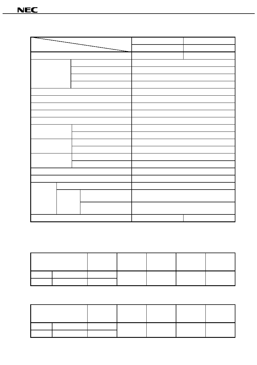
COIL RATING
SEALED TYPE
(at 20
∞
C)
Contact Form
Part Number
Nominal
Voltage
(Vdc)
Coil
Resistance
(
±
10%)
Must Operate
Voltage
(Vdc)
Must Release
Voltage
(Vdc)
Twin
1 Form c
◊
2
ET2-B3M1S
Single
1 Form c
ET1-B3M1S
12
225
6.5
0.9
UNSEALED TYPE
(at 20
∞
C)
Contact Form
Part Number
Nominal
Voltage
(Vdc)
Coil
Resistance
(
±
10%)
Must Operate
Voltage
(Vdc)
Must Release
Voltage
(Vdc)
Twin
1 Form c
◊
2
ET2-B3M1
Single
1 Form c
ET1-B3M1
12
225
6.5
0.9
Items
Types
4
ET2/ET1 SERIES
Data Sheet ER0429EJ1V0DS00
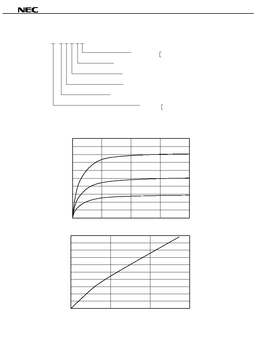
NUMBERING SYSTEM
E T 2 - B 3 M 1 S
Enclosure
Must Operate Voltage
Contact Material
Coil Resistance
Contact carrying current
Type
Nil : Unsealed
S : Sealed
1 : 6.5V
M : Silver oxide complex alloy
3 : 225
B : Standard type
1 : Single
2 : Twin
COIL TEMPERATURE RISE
Test piece : ET1-B3M1S
Coil temperature rise [deg.C]
Coil energized time [min.]
100
90
80
70
60
50
40
30
20
10
0
0
5
10
15
20
Coil saturated temperature rise [deg.C]
Coil energized power [W]
100
90
80
70
60
50
40
30
20
10
0
0
0.5
1
1.5
16V
12V
9V
5
ET2/ET1 SERIES
Data Sheet ER0429EJ1V0DS00
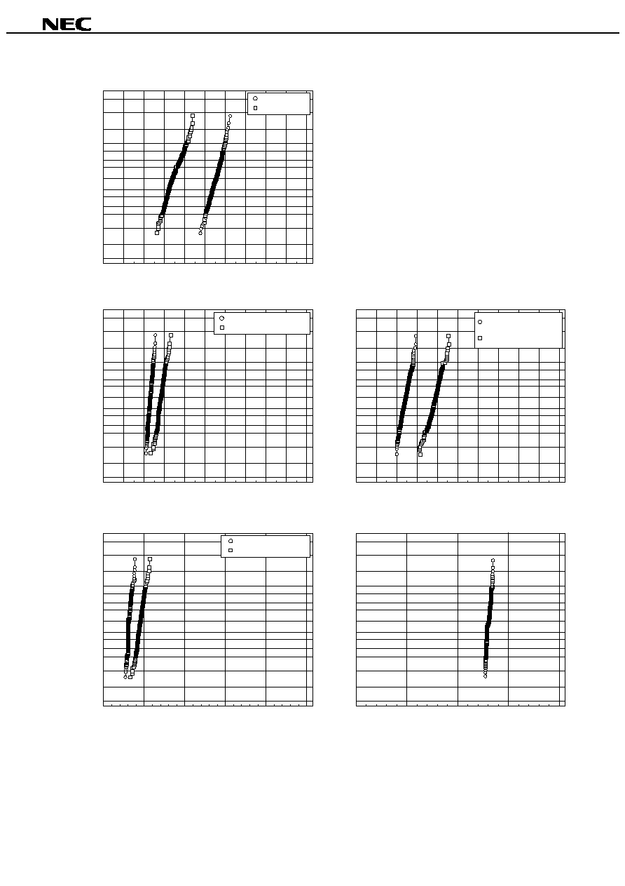
RELAY CHARACTERISTICS DISTRIBUTION (INITIAL)
Operate voltage
Release voltage
Operate/Release voltage [V]
CDF [%]
99.99
99.9
99
95
90
80
70
60
30
20
10
5
1
0.1
0.01
0
1
2
3
4
5
6
7
8
9
10
Excluding contact bounce
Including contact bounce
Operate time [ms]
CDF [%]
99.99
99.9
99
95
90
80
70
50
30
20
10
5
1
0.1
0.01
0
1
2
3
4
5
6
7
8
9
10
Release time [ms]
CDF [%]
99.99
99.9
99
95
80
70
60
50
30
20
10
5
1
0.1
0.01
0
1
2
3
4
5
6
7
8
9
10
Normal open contact
Normal close contact
Contact resistance [m
]
CDF [%]
99.99
99.9
99
95
90
80
70
50
30
20
10
5
1
0.1
0.01
0
5
10
15
20
25
Coil resistance [
]
CDF [%]
99.99
99.9
99
95
90
80
70
50
30
20
10
5
1
0.1
0.01
100
150
200
250
300
Excluding contact bounce
Including contact bounce
with diode