 | –≠–ª–µ–∫—Ç—Ä–æ–Ω–Ω—ã–π –∫–æ–º–ø–æ–Ω–µ–Ω—Ç: LD4606A | –°–∫–∞—á–∞—Ç—å:  PDF PDF  ZIP ZIP |

DATA S H E E T
Document No. ET0117EJ3V1DS00 (3rd edition)
Date Published August 1998 M
Printed in Japan
30 GHz, 380 W CW, HIGH EFFICIENCY, HIGH POWER GAIN
The information in this document is subject to change without notice.
©
1989
HIGH POWER CW KLYSTRONAMPLIFIER
FOR GROUND TERMINALS
LD4606A
For safe use of microwave tubes, refer to NEC document "Safety instructions to all personnel
handling electron tubes" (ET0048EJ
V
UM00)
GENERAL DESCRIPTION
The NEC LD4606A is a five-cavity Klystron amplifier and
ideal for use in the earth-to-satellite communications trans-
mitter.
This is designed for operating at 380 W CW power lev-
els in the frequency range of 27.50 to 29.10 GHz. The in-
stantaneous bandwidth of minus one-decibel is at least
70 MHz over the entire 1.6 GHz range.
The tube is forced-air-cooled at the 380 W operation.
Furthermore, this is of rugged and reliable design of-
fering long-life service.
FEATURES
1 High Efficiency
The DC to RF conversion efficiency is typically 23 %
by incorporating a 39 % depressed collector.
2 High Power Gain
The power gain is typically 40 dB at the 380 W level,
so the driving power is less than 50 mW.
3 Simple Cooling System
The klystron is all forced air cooled with only one
blower, so that the cooling systems are greatly sim-
plified.
4 Permanent Magnet
The klystron is permanent magnet focused, eliminat-
ing entirely the requirement for focusing power sup-
plied and interlock circuits.
5 Rugged Construction
The klystron is designed to be rugged.

2
LD4606A
GENERAL CHARACTERISTICS
ELECTRICAL
Frequency ......................................................
27.50 to 29.10 GHz
Output Power ................................................
380 W
Heater Voltage ................................................
4.3 V
Heater Current ................................................
2.5 A
Type of Cathode .............................................
Indirectly Heated, Impregnated
MECHANICAL
Dimensions ...................................................
See Outline
Focusing
......................................................
Permanent Magnet
Electrical Connections
Heater ......................................................
AMP (861647-8) Receptacle
Heater-Cathode ..........................................
AMP (861647-8) Receptacle
Body, Collector ..........................................
AMP (861647-8) Receptacle
RF Connections
Input .........................................................
Mates with FUBR-260
Output ......................................................
Mates with FUBR-260
Mounting Position ..........................................
Vertical (Cathode down)
Weight .........................................................
45 kg approx.
Cooling
Gun
.........................................................
Forced Air
Collector ...................................................
Forced Air
Body .........................................................
Forced Air
Cavity Tuning Method ....................................
Hand Tuning
ABSOLUTE RATINGS ( Note 1, 2 and 3 )
ELECTRICAL
Min.
Max.
Unit
Heater Voltage ................................................
3.5
5.5
V
Heater Surge Current
....................................
≠
5.5
A
Heater Warm-up Time ....................................
300
≠
s
Body Voltage
................................................
≠
9.5
kV
Collector Voltage .............................................
≠
9.0
kV
Beam Current ................................................
≠
400
mA
Body Current
................................................
≠
20
mA
Collector Current .............................................
≠
400
mA
DC Input Power .............................................
≠
2.5
kW
Load VSWR
Normal Value .............................................
≠
1.2
Instantaneous Value ....................................
≠
1.5
MECHANICAL
Collector Temperature ....................................
≠
200
∞
C
Cooling Air Temperature .................................
≠10
45
∞
C
Air Flow for Collector Body and Gun
...............
238
≠
kg/hr
Ambient Temperature
Operating ...................................................
≠10
45
∞
C
Storage ......................................................
≠40
70
∞
C

3
LD4606A
TYPICAL OPERATION (Note 3, 4 and 5)
Unit
Frequency ...............................................................
28.5
GHz
Heater Voltage (Note 4) .............................................
4.3
V
Heater Current .........................................................
2.5
A
Body Voltage ............................................................
8.5
kV
Body Current ............................................................
10
mA
Collector Voltage ......................................................
5.2
kV
Collector Current ......................................................
300
mA
DC Input Power
......................................................
1.65
kW
Driving Power .........................................................
44
mW
Output Power .........................................................
380
W
Power Gain
............................................................
40
dB
Band Width (-1 dB) ...................................................
80
MHz
Air Flow of Collector, Body and Gun ...........................
250
kg/hr
Note 1 : Absolute rating should not be exceeded under continuous or transient conditions. A single absolute
rating may be the limitation and simultaneous operation at more than one absolute rating may not be
possible. Equipment design should limit voltage and environmental variations so that ratings will be
exceeded.
Note 2 : The Klystron body should be at ground potential in operation.
Note 3 : All voltages are referred to the cathode potential except the heater voltage.
Note 4 : The optimum operating value is shown on a test performance sheet for each tube.
Note 5 : Characteristics and operating values on this Data Sheet are based on performance test. These values
may be changed as a result of additional information or product improvement. NEC should be con-
sulted before using this information for equipment design. This data sheet should not be referred to a
contractual specification.
No part of this document may be copied in any form or by any means without the prior written consent of
NEC Corporation.
NEC Corporation does not assume any liability for infringement of patents, copyrights or other intellectual
property rights of third parties by or arising from use of a device described herein or any other liability arising
from use of such device. No license, either express, implied or otherwise, is granted under any patents, copy-
rights or other intellectual property rights of NEC Corporation or of others.
LD4606A
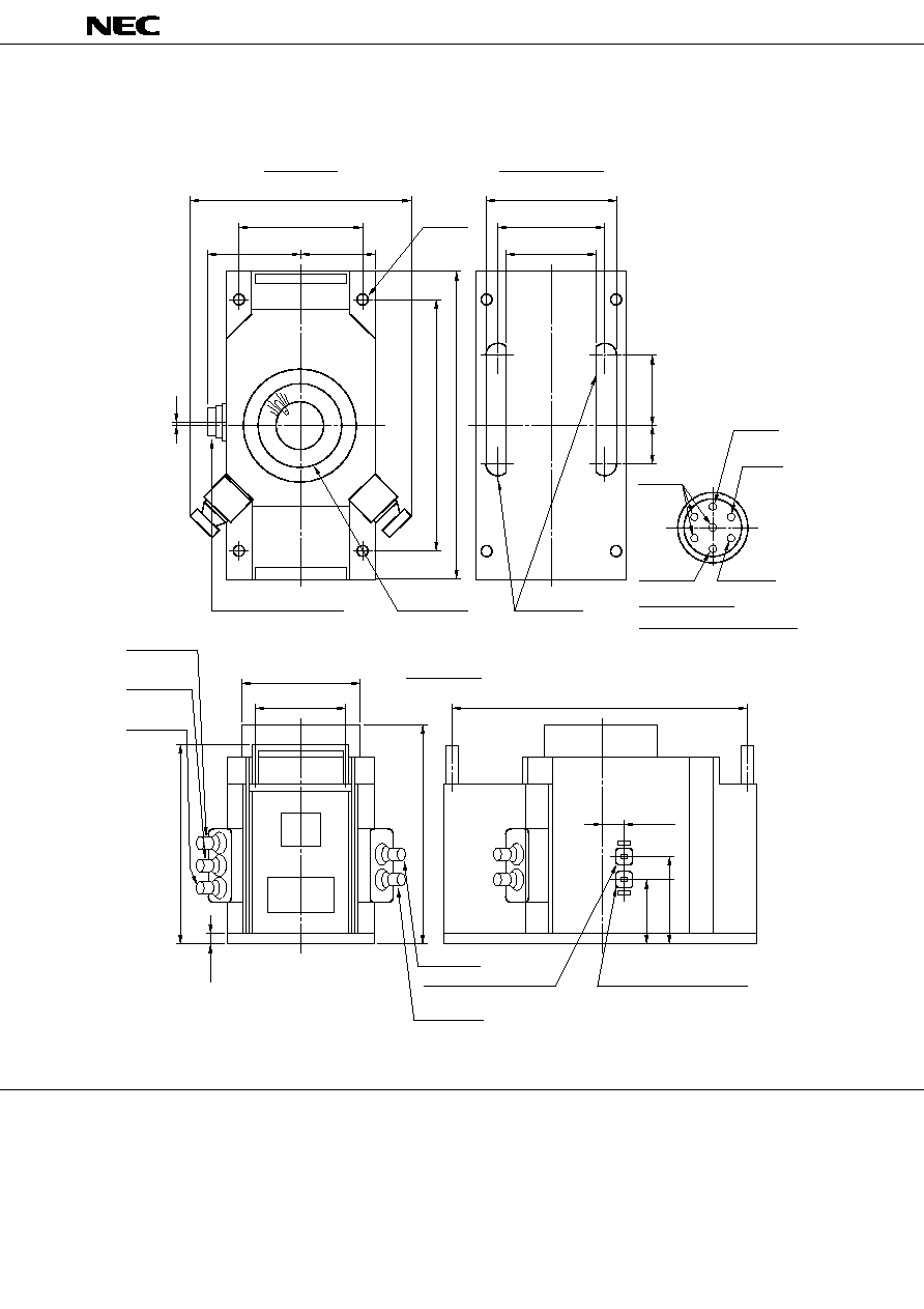
LD4606A OUTLINE (Unit in mm)
Air Inlet
Air Outlet
270 MAX.
TOP VIEW
BOTTOM VIEW
370 MAX.
291.6
±
1.5
6
85
42.5
148
±
1.5
90
152
122
4 - 12
132
±
1.5
100
5th
Cavity
3rd
Cavity
4th Cavity
2nd Cavity
RF Output
(MATES WITH FUBR-260)
RF INput
(MATES WITH FUBR-260)
1st
Cavity
270 MAX.
238.5
15.5
82.1
108.5
344
21.2
105
87.4
Electrical Connection
AMP (861647-8)
Body
AMP (861647-8)
Receptacle PIN Connection
Ground
Heater
Heater
Cathode
Collector
6
5
4
3
2
1
SIDE VIEW