 | –≠–ª–µ–∫—Ç—Ä–æ–Ω–Ω—ã–π –∫–æ–º–ø–æ–Ω–µ–Ω—Ç: LD7126 | –°–∫–∞—á–∞—Ç—å:  PDF PDF  ZIP ZIP |
DATA S H E E T
Document No. ET0213EJ3V0DS00 (3rd edition)
Date Published August 1998 M
Printed in Japan
17 GHz BAND, 2.0 kW/2.4 kW, HIGH EFFICIENCY, HIGH POWER GAIN
The information in this document is subject to change without notice.
©
1996
HIGH POWER CW KLYSTRON
FOR GROUND TERMINALS
LD7126 SERIES
For safe use of microwave tubes, refer to NEC document "Safety instructions to all personnel
handling electron tubes" (ET0048EJ
V
UM00)
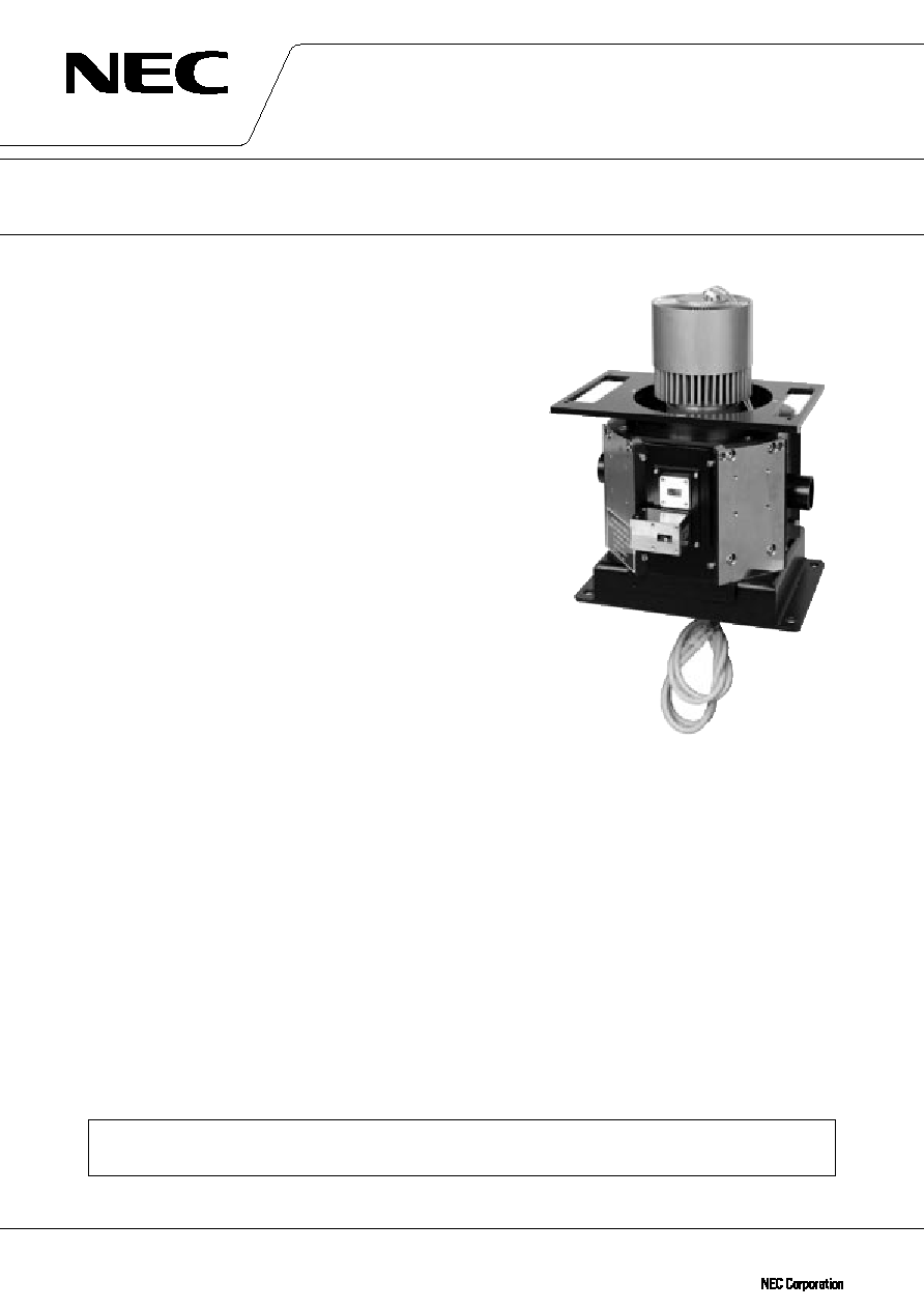
GENERAL DESCRIPTION
NEC LD7126 series are DBS Klystron Amplifiers which employ
five cavities and are ideal for use in the earth-to-satellite commu-
nication systems.
NEC provides the 2.0 kW model (Frequency : 17.3 to 18.1 GHz,
Bandwidth (-1dB) : 80 MHz ) and the 2.4 kW model ( Frequency :
17.3 to 17.8 GHz, Bandwidth (-1dB) : 45 MHz ).
All tubes are forced-air-cooled at any power level. An automatic
channel tuner, which changes the operating frequency very quickly
and simply, is available in all the series.
Furthermore, they are of rugged and reliable design offering
long-life service.
FEATURES
TM Compact and Light Weight (27 kg approx.)
TM High Efficiency
(The DC to RF conversion efficiency is typically 28 % or higher.)
TM High Power Gain
TM Long Life and High Stability
TM Simple Cooling System (forced-air-cooled)
TM Automatic Channel Tuner (8-12 Channels), Hand Tuner model
is also available
TM Permanent Magnet Focusing
TM Rugged Construction

2
LD7126 SERIES
GENERAL CHARACTERISTICS
ELECTRICAL
Frequency ......................................................
17.3 to 18.1 GHz / 17.3 to 17.8 GHz
Output Power ................................................
2.0 kW / 2.4 kW
Heater Voltage ................................................
6.6 V
Heater Current ................................................
3.3 A
Cathode Type ................................................
Indirectly Heated, Impregnated
Cathode Warm-up Time
.................................
300 s
MECHANICAL
Dimensions ...................................................
See Outline
Weight .........................................................
27 kg approx.
Focusing
......................................................
Permanent Magnet
Mounting Position ..........................................
Vertical (Cathode down)
Cooling .........................................................
Forced Air
Electrical Connections ....................................
See Outline
RF Connections
Input .........................................................
Mates with UG-419/U Flange
Output ......................................................
Mates with UG-419/U Flange
Cavity Tuning Method ....................................
8-12 Channel Preset Tuning
(Hand Tuner is also available)
ABSOLUTE RATINGS ( Note 1, 2 and 3 )
ELECTRICAL
Min.
Max.
Unit
Heater Voltage ................................................
4.5
7.5
V
Heater Surge Current
....................................
≠
7.0
A
Heater Current ................................................
≠
4.5
A
Heater Warm-up Time ....................................
300
≠
s
Body Voltage
................................................
≠
10.4
kV
Body Current
................................................
≠
30.0
mA
Collector Voltage .............................................
≠
10.4
kV
Collector Current .............................................
≠
1.1
A
Cathode Current .............................................
≠
1.1
A
DC Input Power .............................................
≠
11.44
kW
Load VSWR
Normal Value .............................................
≠
1.2 : 1
Instantaneous Value ....................................
≠
1.5 : 1
MECHANICAL
Collector Temperature ....................................
≠
+250
∞
C
Cooling Air Temperature .................................
≠10
+50
∞
C
Collector Air Flow ..........................................
650
≠
kg/hr
Body Air Flow ................................................
200
≠
kg/hr
Gun Air Flow
................................................
41
≠
kg/hr
MECHANICAL
Ambient Temperature
Operating ...................................................
+5
+50
∞
C
Storage ......................................................
≠50
+70
∞
C

3
LD7126 SERIES
TYPICAL OPERATION (Note 3, 4 and 5)
2.0 kW
2.4 kW
Unit
Frequency ......................................................
17.3 - 18.1
17.3 - 17.8
GHz
Heater Voltage (Note 4) ....................................
6.6
6.6
V
Heater Current ................................................
3.3
3.3
A
Body Voltage ...................................................
9.8
9.8
kV
Body Current ...................................................
10
10
mA
Collector Voltage .............................................
9.8
9.8
kV
Collector Current .............................................
0.9
0.9
A
Cathode Current .............................................
0.9
0.9
A
DC Input Power
.............................................
8.82
8.82
kW
Driving Power ................................................
84
24
mW
Output Power ................................................
2.1
2.5
kW
Power Gain
...................................................
44
50
dB
Band Width (-1 dB) ..........................................
82
47
MHz
Collector Air Flow
..........................................
660
660
kg/hr
Collector Air Pressure Drop ..............................
1225
1225
Pa
Body Air Flow ................................................
205
205
kg/hr
Body Air Pressure Drop ....................................
200
200
Pa
Gun Air Flow ...................................................
43
43
kg/hr
Note 1 : Absolute rating should not be exceeded under continuous or transient conditions. A single absolute
rating may be the limitation and simultaneous operation at more than one absolute rating may not be
possible. Equipment design should limit voltage and environmental variations so that ratings will be
exceeded.
Note 2 : The Klystron body should be at ground potential in operation.
Note 3 : All voltages are referred to the cathode potential except the heater voltage.
Note 4 : The optimum operating value is shown on a test performance sheet for each tube.
Note 5 : Characteristics and operating values on this Data Sheet are based on performance test. These values
may be changed as a result of additional information or product improvement. NEC should be con-
sulted before using this information for equipment design. This data sheet should not be referred to a
contractual specification.

4
LD7126 SERIES
LD7126 SERIES OUTLINE (Unit in mm)
Preset Tuner Model
5.8
±
0.1
234.7
±
0.5
(260)
(208)
252.5
±
0.25
(275)
(125)
(10)
(128)
(208)
139.7
±
0.25
142.2
±
0.5
133.4
±
0.25
106
±
3
(117.8)
33
±
1.5
(180)
(147)
A
B
Detail B
6.3
+ 0.01
≠ 0.05
5.8
±
0.1
View from A
Electrode
Heater
Heater-Cathode
Color of Lead
Yellow
White
115
±
1
Lock / Unlock Shaft
4-No.4-40 UNC
depth 5.8 MAX.
Body Col & Thermostat
Terminal
Thermostat
(Nomally Close)
RF Output
UG-419 / U
RF Input
UG-419 / U
Channel Shaft
36.84
±
0.3
36.84
±
0.3
17.5
±
0.3
15.5
±
0.3
190
±
2
148
±
2
390 MAX.
(111)
(224)
(201)
26.15
±
0.3
27
±
0.3
(136)
(6.5)
(7)
(8)
(14.65)
(13.4)
(335)
( 38)
4 - 5.6
( 70)
5 - 5

5
LD7126 SERIES
LD7126 SERIES OUTLINE (Unit in mm)
Motor Driven Preset Tuner (Fast Tuning) Model
View from A
Thermostat
(Nomally Close)
RF Output
UG-419 / U
RF Input
UG-419 / U
109
±
2
148
±
2
390 MAX.
5.8
±
0.1
Detail B
6.3
+ 0.01
≠ 0.05
5.8
±
0.1
Electrode
Heater
Heater-Cathode
Color of Lead
Yellow
White
115
±
1
Lock / Unlock Shaft
for urgent
4-No.4-40 UNC
depth 5.8 MAX.
Channel Shaft
15P D-sub
Body. Col & Thermostat
Terminal
36.84
±
0.3
36.84
±
0.3
17.5
±
0.3
15.5
±
0.3
(111)
(224)
(201)
26.15
±
0.3
(
27)
(136)
(6.5)
(
7)
(8)
(14.65)
(13.4)
(335)
(5 - 5)
234.7
±
0.5
(260)
(208)
252.5
±
0.25
(275)
(174)
(125)
(10)
(208)
139.7
±
0.25
142.2
±
0.5
(177.8)
(150)
133.4
±
0.25
106
±
3
33
±
1.5
A
B
4 - 5.6
4 - 11
( 70)