 | –≠–ª–µ–∫—Ç—Ä–æ–Ω–Ω—ã–π –∫–æ–º–ø–æ–Ω–µ–Ω—Ç: LD7237 | –°–∫–∞—á–∞—Ç—å:  PDF PDF  ZIP ZIP |
DATA S H E E T
Document No. ET0159EJ2V1DS00
Date Published August 1998 M
Printed in Japan
DBS Band, 400 W CW, PPM FOCUSING, HIGH POWER GAIN
The information in this document is subject to change without notice.
©
1996
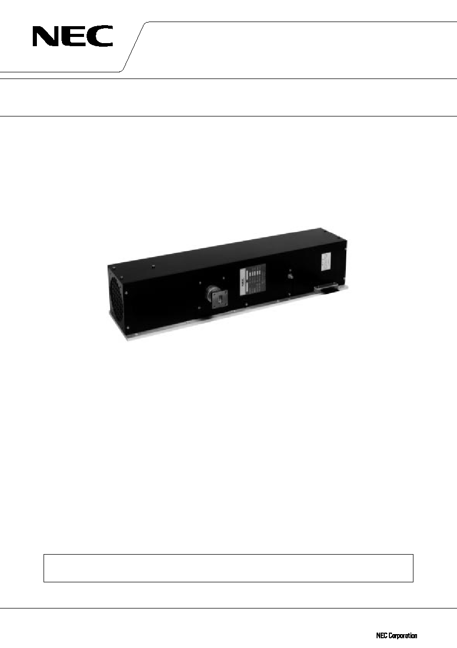
HIGH POWER TRAVELING WAVE TUBE
FOR DBS GROUND TERMINALS
LD7237
GENERAL DESCRIPTION
NEC LD7237 is PPM-focused traveling wave tube designed for use as final amplifier in the earth-to-satellite
communications transmitter.
This is capable of delivering an output power of 400 W over the range of 17.3 to 18.1 GHz and provides a high
power gain of 53 dB at 400 W output power.
Furthermore, this is of rugged and reliable design offering long-life service.
LD7237 is fully compatible with TH3694B.
FEATURES
TM High Power Gain
The power gain is typically 53dB at 400 W level.
TM Simple Cooling System
The tube is forced-air-cooled, so that the cooling systems are greatly simplified.
TM PPM Focusing
The tube is PPM (Periodic Permanent Magnet)-focused, eliminating entirely the focusing power supplies and
interlock circuits.
TM Rugged Construction
The tube is designed to be rugged, therefore it is suitable for the transportable systems.
TM Long Life and High Stability
The tube employs an advanced impregnated cathode with a low operating temperature for long life.
TM Microdischarge Free
The tube is carefully designed to be free from microdischarge in the electron gun for long term operation,
therefore it is suitable for digital communication service.
For safe use of microwave tubes, refer to NEC document "Safety instructions to all personnel
handling electron tubes" (ET0048EJ
V
UM00)

2
LD7237
GENERAL CHARACTERISTICS
ELECTRICAL
Frequency .................................................................................. 17.3 to 18.1 GHz
Output Power ............................................................................ 400 W
Heater Voltage ........................................................................... 6.3 V
Heater Current ........................................................................... 1.4 A
Type of Cathode ........................................................................ Indirectly heated, Impregnated
Cathode Warm-up Time ........................................................... 300 s
MECHANICAL
Dimensions ................................................................................ See Outline Drawing
Weight ........................................................................................ 6.0 kg approx.
Focusing .................................................................................... Periodic Permanent Magnet
Mounting Position .................................................................... Any
Electrical Connections .............................................................. AMP 861647-8 multi-pin connector
Heater, Heater-Cathode
Helix, Anode, Collector
and Thermal Protection
RF Connections
Input ................................................................................... Mates with SMA-Female
Output ................................................................................ Mates with UBR-140 Flange
Cooling ....................................................................................... Forced Air

3
LD7237
ABSOLUTE RATINGS
(Note 1, 2 and 3)
ELECTRICAL
Min.
Max.
Unit
Heater Voltage ..................................................................
6.0
6.6
V
Heater Surge Current ......................................................
≠
4.5
A
Heater Current ..................................................................
≠
3.0
A
Heater Warm-up Time .....................................................
300
≠
s
Helix Voltage ....................................................................
9.5
10.75
kV
Helix Current ....................................................................
≠
15
mA
Anode Voltage ..................................................................
8.55
10.25
kV
Anode Current ..................................................................
≠
0.5
mA
Collector Voltage ..............................................................
4.0
5.5
kV
Cathode Current ...............................................................
≠
350
mA
RF Drive Power ................................................................
≠
25
mW
Load VSWR ......................................................................
≠
1.5
MECHANICAL
Min.
Max.
Unit
Temperature at output Flange ........................................
≠
100
∞C
Air Flow ............................................................................
195
≠
kg/hr
Ambient Temperature
Storage .....................................................................
≠40
+80
∞C
Operation ..................................................................
≠10
+50
∞C

4
LD7237
TYPICAL OPERATION
(Note 2, 3 and 5)
Unit
Frequency ............................................................................... 17.3 to 18.1
GHz
Output Power .........................................................................
400
W
Heater Voltage (Note 4) ........................................................
6.3
V
Heater Current ........................................................................
1.4
A
Helix Voltage ...........................................................................
10
kV
Helix Current ...........................................................................
2
mA
Anode Voltage ........................................................................
9.5
kV
Anode Current ........................................................................
0.1
mA
Collector Voltage ....................................................................
4.7
kV
Cathode Current .....................................................................
290
mA
Power Gain
at small signal ..................................................................
58
dB
at rated output power .....................................................
53
dB
Gain Variation at small signal ...............................................
2
dB/800 MHz
Gain Slope at small signal ....................................................
0.01
dB/MHz
AM-PM Conversion
at small signal ..................................................................
0.5
∞
/dB
at rated output power .....................................................
2.0
∞
/dB
3rd Order Intermodulation
(two equal carriers, 40 W total) ......................................
≠32
dBc
Cooling Air Flow ....................................................................
195
kg/hr
Pressure Drop .........................................................................
650
Pa
Note 1 : Absolute rating should not be exceeded under continuous or transient conditions.
A single absolute rating may be the limitation and simultaneous operation at more than one absolute
rating may not be possible.
Note 2 : The tube body is at ground potential in operation.
Note 3 : All voltages are refferred to the cathode potential except the heater voltage.
Note 4 : The optimum operating parameters are shown on a test performance sheet for each tube.
Note 5 : These characteristics and operating values may be changed as a result of additional information or product
improvement. NEC should be consulted before using this information for equipment design.
This data sheet should not be referred to a contractual specification.

5
LD7237
LD7237 OUTLINE
(Unit in mm)
Pin No.
LEAD NAME
1
HEATER / CATHODE
2
HEATER
3
COLLECTOR
4
THERMAL PROTECTION
5
OPEN (NO CONNECTION)
6
HELIX (GROUND)
7
ANODE
PIN ASSIGNMENT
55
83
AIR OUTLET
4 - M3
98
66
87.5 MAX.
86
PIN CONNECTION
7
1
2
3
4
6
5
AMP861647-8 CONNECTOR
10- 6
4-M4
111
127 MAX.
85 MAX.
210 MAX.
29
157
900
±
50
101
101
101
19
6
RF INPUT
SMA FEMALE
RF OUTPUT
Mates with UBR-140 FLANGE
110 MAX.
178
505 MAX.
175
AMP861647-8
MULTI-PIN CONNECTOR
NOTE THERMAL PROTECTION : N / C (Normally
Closed) CONTACT