DATA SHEET
The information in this document is subject to change without notice. Before using this document, please
confirm that this is the latest version.
Not all devices/types available in every country. Please check with local NEC representative for
availability and additional information.
©
1999
Document No. P14039EJ2V0DS00 (2nd edition)
Date Published July 1999 NS CP(K)
Printed in Japan
LASER DIODE
NDL7605P Series
1 310 nm OPTICAL CATV RETURN PATH APPLICATIONS
InGaAsP MQW DFB LASER DIODE MODULE WITH ISOLATOR
The mark
∑
∑
∑
∑
shows major revised points.
DESCRIPTION
The NDL7605P Series is a 1 310 nm uncooled isolated coaxial DFB laser diode. It is especially designed for
optical CATV return path applications.
FEATURES
∑ Low distortion
IMD2 =
-
50 dBc MAX.
*1
@ T
C
= 25
∞
C
IMD2 =
-
45 dBc MAX.
*1
@ T
C
=
-
40 to +85
∞
C
IMD3 =
-
60 dBc MAX.
*1
@ T
C
=
-
40 to +85
∞
C
∑ Output power
P
f
= 2.0 mW
∑ Long wavelength
p
= 1 310 nm
∑ Internal InGaAs monitor PD and isolator
∑ Single mode fiber pigtail with FC-UPC, SC-UPC or SC-APC connector
∑ Wide operating temperature range
T
C
=
-
40 to +85
∞
C
*1 2-ch, Optical loss = 7 dB, OMI = 10 %/ch
Data Sheet P14039EJ2V0DS00
2
NDL7605P Series
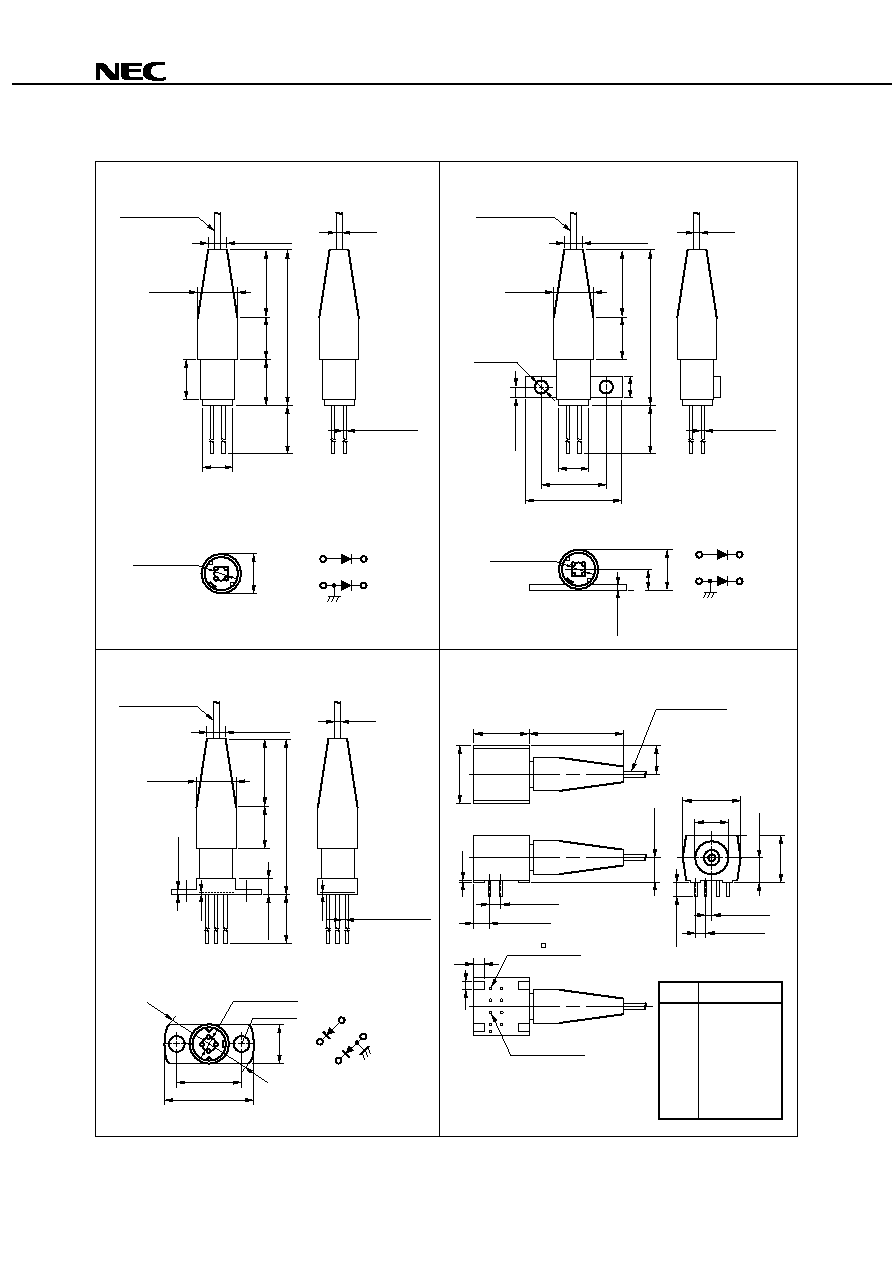
PACKAGE DIMENSIONS (in millimeters)
NDL7605P
Optical Fiber
SM-9/125
Length: 1 m
5.3±0.8
20±1.0
29.0±1.0
6±0.1
4.1±0.8
3.2±0.25
7±0.2
8
15
0.9
0.45±0.05
PIN CONNECTIONS
4
1
3
2
PD
LD
CASE
7±0.2
4 3
2
1
P.C.D. = 2
NDL7605P1
0.9
0.45±0.05
Optical Fiber
SM-9/125
Length: 1 m
2.0±0.2
20±1.0
29.0±1.0
4.0±0.2
3.2±0.25
7±0.2
8
15
12.7±0.2
17.0±0.2
2≠ 2.2
6±0.1
PIN CONNECTIONS
4
1
3
2
PD
LD
CASE
4 3
2
1
7.2±0.3
1.0±0.1
P.C.D. = 2
3.7±0.3
NDL7605P2
Optical Fiber
SM-9/125
Length: 1 m
19.5±1.0
29.3±1.0
3.2±0.25
7±0.2
8
15
0.5±0.2
0.3
2.5±1.0
0.9
4≠
0.45±0.05
0.3
PIN CONNECTIONS
PD
3
2
4
1
LD
CASE
7±0.2
12±0.15
16.0
16
P.C.D. = 2
NDL7605P4
PIN CONNECTIONS
Pin No.
Function
1
2
3
4
5
6
7
8
NC
PD anode
PD cathode
NC
NC
LD cathode
LD anode
NC
12.6±0.2
6.3±0.2
12.6±0.2
24.7±1.0
Optical Fiber
SM-9/125
Length: 1 m
7±0.2
12.6±0.2
10.2±0.2
1.27±0.2
2.54±0.3
5.1±0.2
3.6±0.5
5.1±0.1
3.81±0.3
2.54±0.3
0.2
4
3
2
1
5
6
7
8
4≠ 0.45
PIN 2, 3, 6, 7
4≠0.5
PIN 1, 4, 5, 8
2
3
2≠ 2.5
4
3
2
1
Data Sheet P14039EJ2V0DS00
3
NDL7605P Series
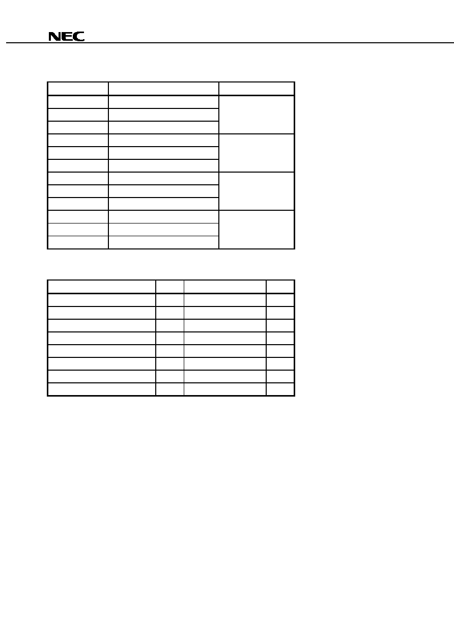
ORDERING INFORMATION
Part Number
Available Connector
Flange Type
NDL7605PC
With FC-UPC Connector
No Flange
NDL7605PD
With SC-UPC Connector
NDL7605PX
With SC-APC Connector
NDL7605P1C
With FC-UPC Connector
Flat Mount Flange
NDL7605P1D
With SC-UPC Connector
NDL7605P1X
With SC-APC Connector
NDL7605P2C
With FC-UPC Connector
Vertical Flange
NDL7605P2D
With SC-UPC Connector
NDL7605P2X
With SC-APC Connector
NDL7605P4C
With FC-UPC Connector
Lead Bend
NDL7605P4D
With SC-UPC Connector
NDL7605P4X
With SC-APC Connector
ABSOLUTE MAXIMUM RATINGS (T
C
= 25
∞
∞
∞
∞
C, unless otherwise specified)
Parameter
Symbol
Ratings
Unit
Optical Output Power from Fiber
P
f
5
mW
Forward Current of LD
I
F
I
th
+ 50
mA
Reverse Voltage of LD
V
R
2.0
V
Forward Current of PD
I
F
10
mA
Reverse Voltage of PD
V
R
15
V
Operating Case Temperature
T
C
-
40 to +85
∞
C
Storage Temperature
T
stg
-
40 to +85
∞
C
Lead Soldering Temperature (10 s)
T
sld
260
∞
C
Data Sheet P14039EJ2V0DS00
4
NDL7605P Series
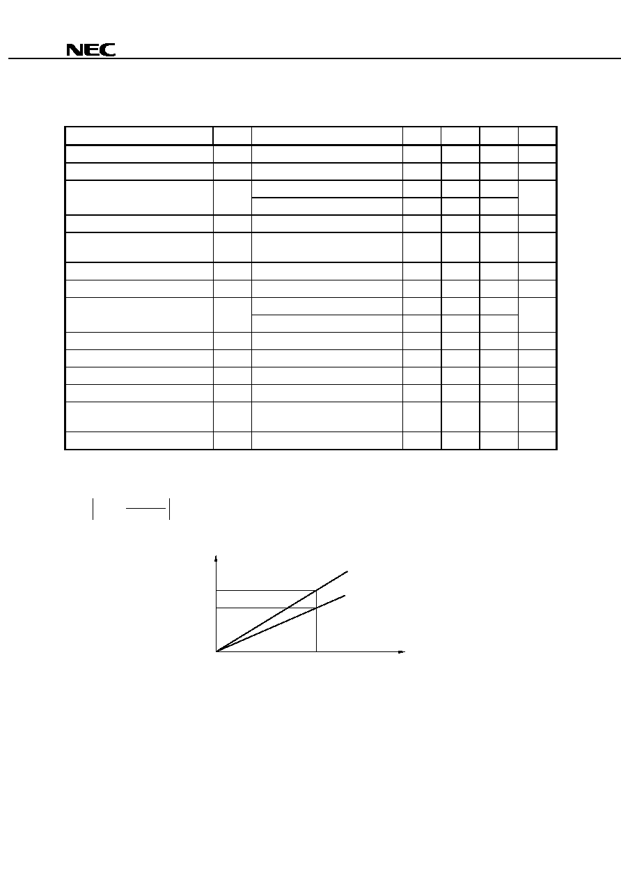
ELECTRO-OPTICAL CHARACTERISTICS
(T
C
= 25
∞
∞
∞
∞
C, Optical Reflection
-
-
-
-
50 dB, unless otherwise specified)
Parameter
Symbol
Conditions
MIN.
TYP.
MAX.
Unit
Forward Voltage
V
F
I
F
= 30 mA
0.9
1.1
1.3
V
Optical Output Power from Fiber
P
f
CW
2.0
mW
Threshold Current
I
th
CW
15
30
mA
CW, T
C
= 85
∞
C
40
60
Differential Efficiency from Fiber
d
P
f
= 2.0 mW
0.080
0.200
W/A
Temperature Dependence of
Differential Efficiency from Fiber
d
P
f
= 2.0 mW,
(85
∞
C) /
(25
∞
C)
-
3.0
dB
Peak Emission Wavelength
p
P
f
= 2.0 mW, RMS (
-
20 dB)
1 290
1 310
1 330
nm
Side Mode Suppression Ratio
SMSR
P
f
= 2.0 mW
30
dB
2nd Order Inter-modulation Distortion
IMD2
*1
-
50
dBc
*1, T
C
=
-
40 to +85
∞
C
-
45
3rd Order Inter-modulation Distortion
IMD3
*1, T
C
=
-
40 to +85
∞
C
-
60
dBc
Carrier to Noise Ratio
CNR
*1, T
C
=
-
40 to +85
∞
C
52
dB
Monitor Current
I
m
V
R
= 5 V, P
f
= 2.0 mW
100
500
1 000
µ
A
Dark Current
I
D
V
R
= 5 V
0.1
10
nA
Tracking Error
*2
I
m
= const., P
f
= 2.0 mW,
T
C
=
-
40 to +85
∞
C
1.5
dB
Optical Isolation
ISO
30
dB
*1 Conditions: P
f
= 2.0 mW, T
C
= 25
∞
C, 2 channel unmodulated carriers 13 MHz and 19 MHz,
Optical Reflection =
-
50 dB, Optical Loss = 7 dB, OMI = 10 %/ch
*2
= 10 log
I
m
P
f
(mW)
P
f
2.0
I
m
(@ P
f
(25 ∞C) = 2.0 mW)
0
T
C
= ≠40 to +85 ∞C
T
C
= 25 ∞C
P
f
2.0 mW
Data Sheet P14039EJ2V0DS00
5
NDL7605P Series
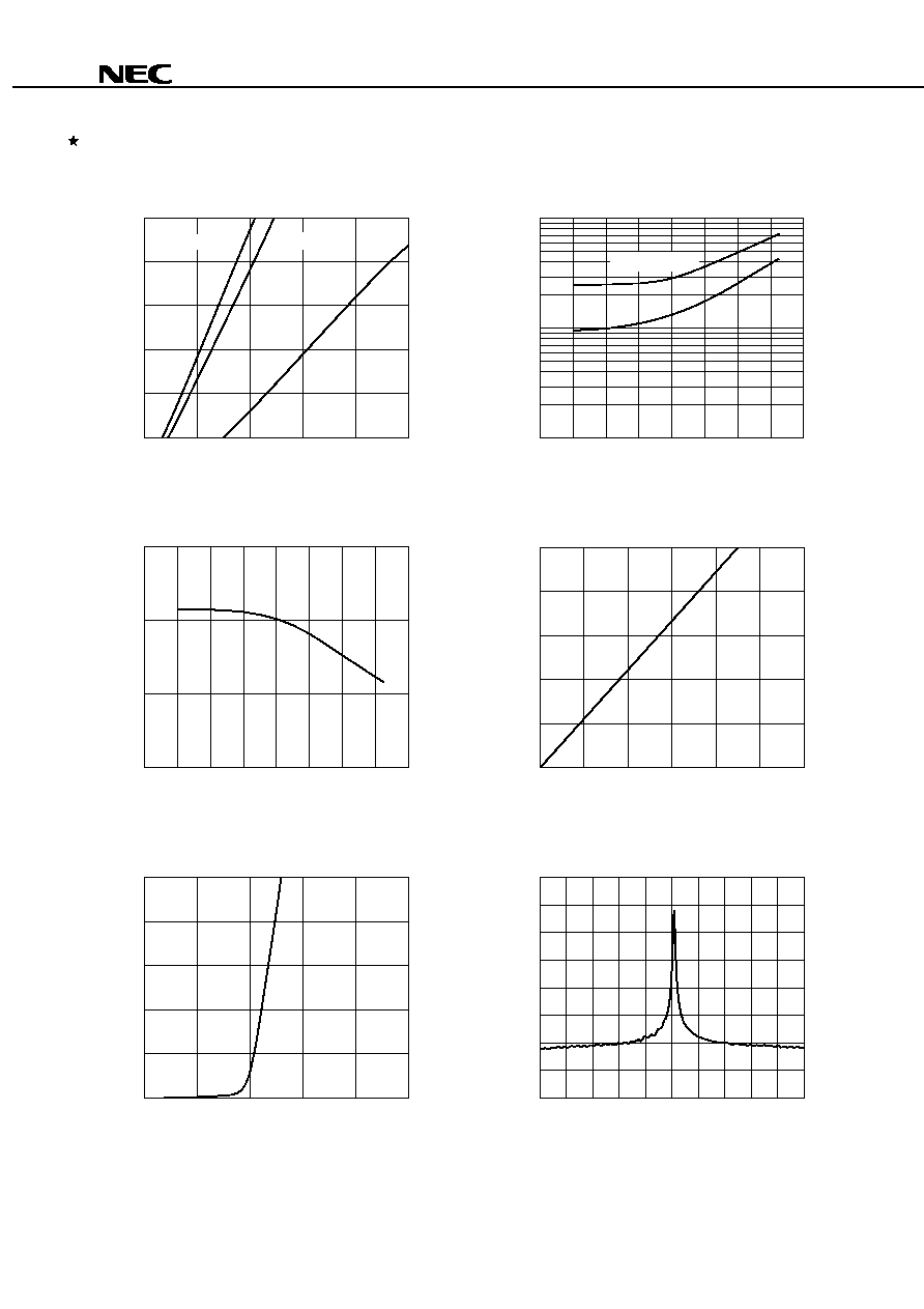
TYPICAL CHARACTERISTICS (T
C
= 25
∞
∞
∞
∞
C, unless otherwise specified)
FORWARD CURRENT vs.
FORWARD VOLTAGE
Forward Current I
F
(mA)
Forward Voltage V
F
(V)
100
60
40
20
0
80
0.5
1.0
1.5
2.0
2.5
LONGITUDINAL MODE FROM FIBER
Relative Intensity (dB)
Wavelength
(nm)
10
≠10
≠30
≠50
≠70
0
≠20
≠40
≠60
1 300
1 310
1 320
100
10
1
≠60
0
40
80
100
≠40
≠20
20
60
OPERATING CURRENT AND THRESHOLD
CURRENT vs. CASE TEMPERATURE
Case Temperature T
C
(∞C)
Operating Current I
op
(mA),
Threshold Current I
th
(mA)
I
th
I
op
@P
f
= 2 mW
0.18
0.12
0.06
0.00
≠40
≠60
≠20
0
20
40
60
80
100
TEMPERATURE DEPENEDENCE OF
DIFFERENTIAL EFFICIENCY FROM FIBER
Case Temperature T
C
(∞C)
Differential Efficiency from Fiber
d
(W/A)
0
1.0
2.0
3.0
4.0
5.0
20
40
60
80
100
Forward Current I
F
(mA)
Optical Output Power from Fiber P
f
(mW)
Optical Output Power from Fiber P
f
(mW)
OPTICAL OUTPUT POWER FROM
FORWARD CURRENT
T
C
= ≠40 ∞C
+85 ∞C
0.5
0
1.0
2.0
3.0
4.0
5.0
1.0
1.5
Monitor Current I
m
(mA)
OPTICAL OUTPUT POWER FROM
FIBER vs.MONITOR CURRENT
+25 ∞C
Data Sheet P14039EJ2V0DS00
6
NDL7605P Series
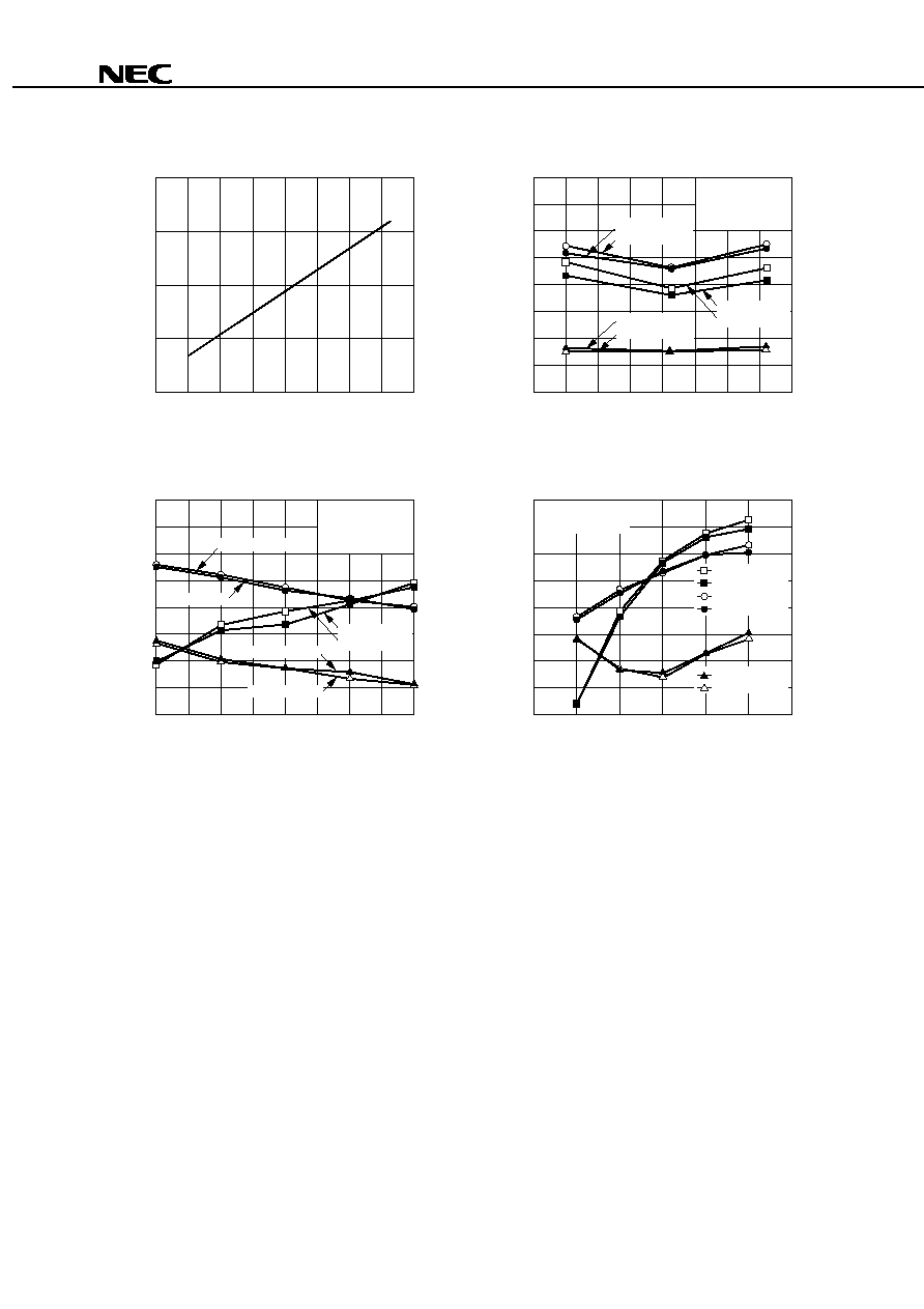
1 320
1 315
1 310
1 305
1 300
≠20
0
40
80
100
≠60
≠40
20
60
TEMPERATURE DEPENDENCE OF
PEAK EMISSION WAVELENGTH
Case Temperature T
C
(∞C)
Peak Emission Wavelength
p
(nm)
≠20
0
40
80
100
≠60
≠40
20
60
≠80
≠75
≠70
≠65
≠60
≠55
≠50
≠45
≠40
46
48
50
52
54
56
58
60
62
P
f
= 2 mW, 2-ch,
7 dB optical loss,
m = 10 %/ch
IMD2@6 MHz
IMD2@32 MHz
IMD3@7 MHz
IMD3@25 MHz
CNR@13 MHz
CNR@19 MHz
Case Temperature T
C
(∞C)
2nd Order Inter-modulation Distortion IMD2 (dBc),
Carrier to Noise Ratio CNR (dB)
3rd Order Inter-modulation Distortion IMD3 (dBc)
IMD2, IMD3, CNR vs.
CASE TEMPERATURE
Optical Modulation Index OMI (%/ch)
2nd Order Inter-modulation Distortion IMD2 (dBc),
Carrier to Noise Ratio CNR (dB)
3rd Order Inter-modulation Distortion IMD3 (dBc)
Optical Output Power from Fiber P
f
(mW)
2nd Order Inter-modulation Distortion IMD2 (dBc),
Carrier to Noise Ratio CNR (dB)
3rd Order Inter-modulation Distortion IMD3 (dBc)
IMD2, IMD3, CNR vs. OPTICAL
OUTPUT POWER FROM FIBER
IMD2, IMD3, CNR vs.
OPTICAL MODULATION INDEX
2-ch,
7 dB optical loss,
m = 10 %/ch
P
f
= 2 mW, 2-ch,
7 dB optical loss
≠80
1.0
1.5
2.0
2.5
3.0
≠75
≠70
≠65
≠60
≠55
≠50
≠45
≠40
46
48
50
52
54
56
58
60
62
CNR@13 MHz
CNR@19 MHz
IMD3@25 MHz
IMD3@7 MHz
IMD2@6 MHz
IMD2@32 MHz
≠80
≠75
≠70
≠65
≠60
≠55
≠50
≠45
≠40
46
48
50
52
54
56
58
60
62
0
5
10
15
20
25
30
CNR@19 MHz
CNR@13 MHz
IMD2@32 MHz
IMD2@6 MHz
IMD3@7 MHz
IMD3@25 MHz
Remark The graphs indicate nominal characteristics.

Data Sheet P14039EJ2V0DS00
7
NDL7605P Series
REFERENCE
Document Name
Document No.
NEC semiconductor device reliability/quality control system
C11159E
Quality grades on NEC semiconductor devices
C11531E
Semiconductor device mounting technology manual
C10535E
SEMICONDUCTORS SELECTION GUIDE Products & Packages (CD-ROM)
X13769X

Data Sheet P14039EJ2V0DS00
8
NDL7605P Series
[MEMO]

Data Sheet P14039EJ2V0DS00
9
NDL7605P Series
[MEMO]

Data Sheet P14039EJ2V0DS00
10
NDL7605P Series
[MEMO]
Data Sheet P14039EJ2V0DS00
11
NDL7605P Series
CAUTION
Within this device there exists GaAs (Gallium Arsenide) material which is a
harmful substance if ingested. Please do not under any circumstances break the
hermetic seal.
DANGER
INVISIBLE LASER RADIATION
AVOID DIRECT EXPOSURE TO BEAM
OUTPUT POWER mW MAX
WAVELENGTH nm
CLASS lllb LASER PRODUCT
AVOID EXPOSURE-Invisible
Laser Radiation is emitted from
this aperture
NEC Corporation
NEC Building, 7-1, Shiba 5-chome,
Minato-ku, Tokyo 108-01, Japan
Type number:
Manufactured:
Serial Number:
This product conforms to FDA
regulations as applicable
to standards 21 CFR Chapter 1.
Subchapter J.
SEMICONDUCTOR LASER

NDL7605P Series
The export of this product from Japan is prohibited without governmental license. To export or re-export this product from
a country other than Japan may also be prohibited without a license from that country. Please call an NEC sales
representative.
∑
The information in this document is subject to change without notice. Before using this document, please
confirm that this is the latest version.
∑
No part of this document may be copied or reproduced in any form or by any means without the prior written
consent of NEC Corporation. NEC Corporation assumes no responsibility for any errors which may appear in
this document.
∑
NEC Corporation does not assume any liability for infringement of patents, copyrights or other intellectual property
rights of third parties by or arising from use of a device described herein or any other liability arising from use
of such device. No license, either express, implied or otherwise, is granted under any patents, copyrights or other
intellectual property rights of NEC Corporation or others.
∑
Descriptions of circuits, software, and other related information in this document are provided for illustrative
purposes in semiconductor product operation and application examples. The incorporation of these circuits,
software, and information in the design of the customer's equipment shall be done under the full responsibility
of the customer. NEC Corporation assumes no responsibility for any losses incurred by the customer or third
parties arising from the use of these circuits, software, and information.
∑
While NEC Corporation has been making continuous effort to enhance the reliability of its semiconductor devices,
the possibility of defects cannot be eliminated entirely. To minimize risks of damage or injury to persons or
property arising from a defect in an NEC semiconductor device, customers must incorporate sufficient safety
measures in its design, such as redundancy, fire-containment, and anti-failure features.
∑
NEC devices are classified into the following three quality grades:
"Standard", "Special", and "Specific". The Specific quality grade applies only to devices developed based on a
customer designated "quality assurance program" for a specific application. The recommended applications of
a device depend on its quality grade, as indicated below. Customers must check the quality grade of each device
before using it in a particular application.
Standard: Computers, office equipment, communications equipment, test and measurement equipment,
audio and visual equipment, home electronic appliances, machine tools, personal electronic
equipment and industrial robots
Special: Transportation equipment (automobiles, trains, ships, etc.), traffic control systems, anti-disaster
systems, anti-crime systems, safety equipment and medical equipment (not specifically designed
for life support)
Specific: Aircraft, aerospace equipment, submersible repeaters, nuclear reactor control systems, life
support systems or medical equipment for life support, etc.
The quality grade of NEC devices is "Standard" unless otherwise specified in NEC's Data Sheets or Data Books.
If customers intend to use NEC devices for applications other than those specified for Standard quality grade,
they should contact an NEC sales representative in advance.
M7 98. 8