 | ÐлекÑÑоннÑй компоненÑ: NE38018 | СкаÑаÑÑ:  PDF PDF  ZIP ZIP |
Äîêóìåíòàöèÿ è îïèñàíèÿ www.docs.chipfind.ru
Hetero Junction Field Effect transistor
NE38018
L to S BAND LOW NOISE AMPLIFER
N-CHANNEL HJ-FET
©
1998
Document No. P13494EJ1V0DS00 (1st edition)
Date Published August 1998 N CP(K)
Printed in Japan
PRELIMINARY DATA SHEET
FEATURES
Super Low noise figure & High Associated Gain
NF = 0.55 dB typ. Ga = 14.5 dB typ. OIP
3
= 22 dBm (V67), OIP
3
= 23 dBm (V68) typ. at f = 2 GHz
NF = 0.4 dB typ. Ga = 20 dB typ. at f = 900 MHz
4 pins super mini mold package
Wg = 800
µ
m
ORDERING INFORMATION (PLAN)
Part Number
Quantity
Packing Style
NE38018-T1
3 kpcs/Reel.
Embossed tape 8 mm wide.
Pin3 (Source), Pin4 (Drain) face to perforation side of the tape.
NE38018-T2
3 kpcs/Reel.
Embossed tape 8 mm wide.
Pin1 (Source), Pin2 (Gate) face to perforation side of the tape.
Remark Please contact with responsible NEC person, if you require evaluation sample.
(Part number for sample order: NE38018)
ABSOLUTE MAXIMUM RATINGS (T
A
= 25°C)
Parameter
Symbol
Ratings
Unit
Drain to Source Voltage
V
DS
4.0
V
Gate to Source Voltage
V
GS
3.0
V
Drain Current
I
D
I
DSS
mA
Gate Current
I
G
100
µ
A
Total Power Temperature
P
tot
150
mA
Channel Temperature
T
ch
125
°C
Storage Temperature
T
stg
65 to +125
°C
RECOMMENDED OPERATING CONDITIONS (T
A
= 25°C)
Parameter
Symbol
MIN.
TYP.
MAX.
Unit
Drain to Source Voltage
V
DS
1
2
3
V
Drain Current
I
D
2
5
30
mA
Input Power
P
in
0
dBm
The information in this document is subject to change without notice.
2
NE38018
ELECTRICAL CHARACTERISTICS (T
A
= 25°C)
Parameter
Symbol
Test Conditions
MIN.
TYP.
MAX.
Unit
Gate to Source Leak Current
I
GSO
V
GS
= 3 V
1.0
20
µ
A
Saturated Drain Current
I
DSS
V
DS
= 2 V V
GS
= 0 V
40
170
mA
Gate to Source Cut off Voltage
V
GS(off)
V
DS
= 2 V I
DS
= 100
µ
A
0.1
1.5
V
Transconductance
g
m
V
DS
= 2 V I
DS
= 5 mA
50
mS
Noise Figure
NF
0.55
1.0
dB
Associated Gain
Ga
12.5
14.5
dB
Power Gain
Gs
V
DS
= 2 V I
DS
= 5 mA
f = 2 GHz
16
dB
17 (V67)
Output Power at 1 dB Gain
Compression Point
P
0(1 dB)
V
DS
= 3 V I
DS
= 30 mA
f = 2 GHz
18 (V68)
dBm
22 (V67)
Output Third-Order Distortion
Intercept Point
OIP
3
V
DS
= 2 V I
DS
= 5 mA
f = 2 GHz
23 (V68)
dBm
I
DSS
CLASSIFICATIONS
Rank
I
DSS
(mA)
Marking
67
40 to 90
V67
68
70 to 170
V68
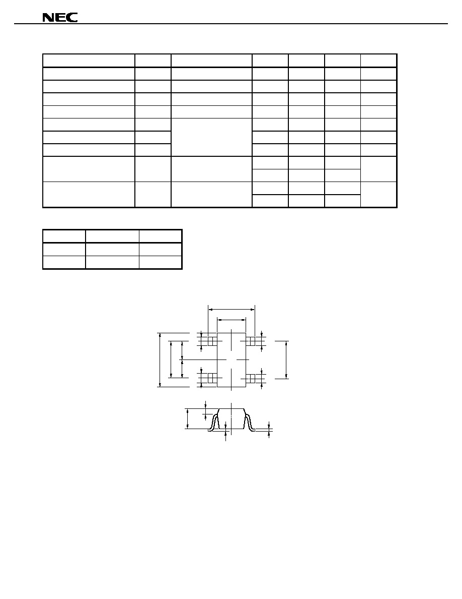
DIMENSIONS (Unit: mm)
0.3
+0.1 0.05
0.3
+0.1 0.05
0.15
+0.1 0.05
0.3
+0.1 0.05
0.4
+0.1 0.05
(1.3)
0.65
0.60
(1.25)
2.0±0.2
0.9±0.1
1.25±0.1
2.1±0.2
1
0.3
0 to 0.1
2
43
V67
PIN CONNECTIONS
1. Source
2. Gate
3. Source
4. Drain
Preliminary Data Sheet
3
NE38018
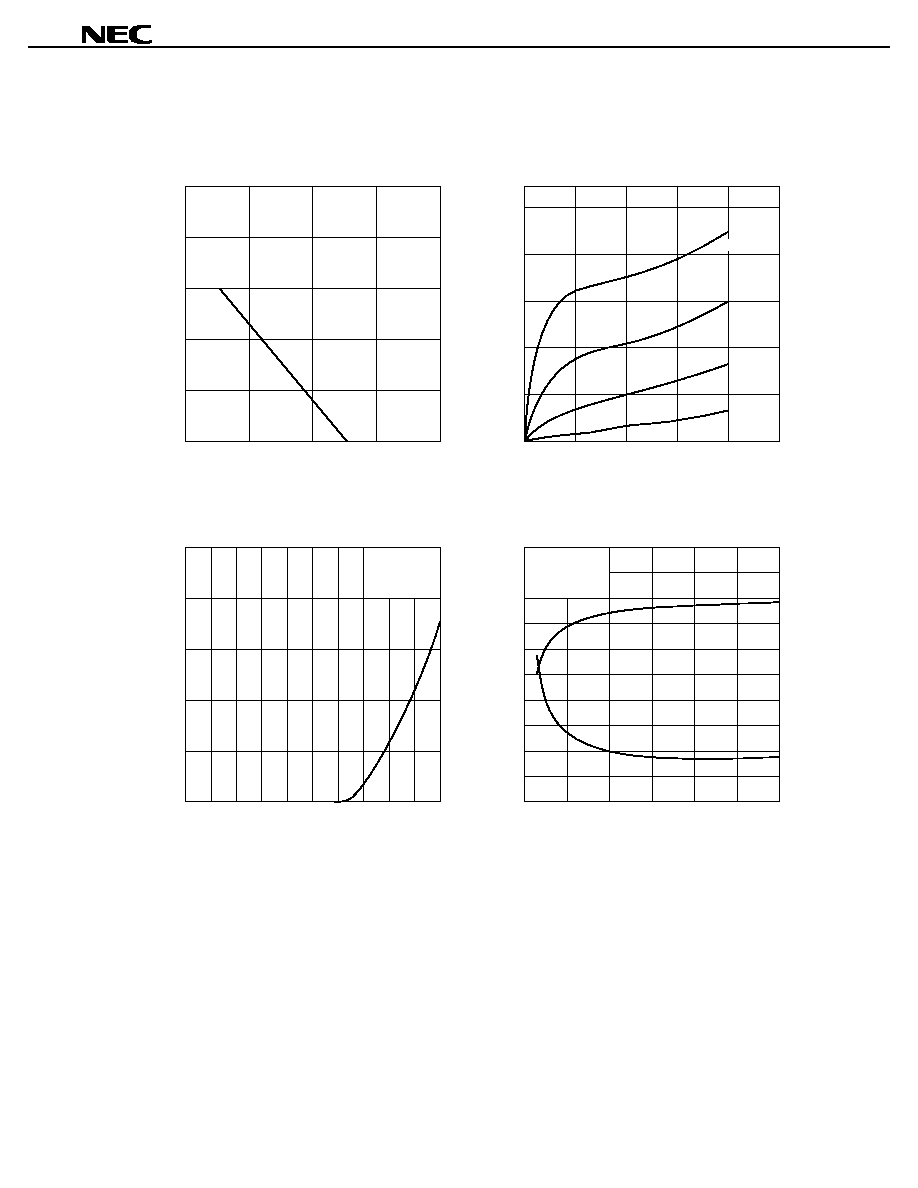
TYPICAL CHARACTERISTICS (T
A
= 25°C)
250
200
150
100
50
100
80
60
40
20
0
2.0
100
80
60
40
20
0
1.0
0
0
2.0
1.8
1.6
1.4
1.2
1.0
0.8
0.6
0.4
0.2
20
18
16
14
12
10
8
6
4
2
0
5
10
15
20
25
30
50
100
150
200
0
1
2
3
4
V
GS
=
0 V
V
DS
= 2 V
V
DS
= 2 V
f = 2 GHz
0.2 V
0.4 V
0.6 V
5
G
a
NF
TOTAL POWER DISSIPATION vs.
AMBIENT TEMPERATURE
DRAIN CURRENT vs.
DRAIN TO SOURCE VOLTAGE
DRAIN CURRENT vs.
GATE TO SOURCE VOLTAGE
NOISE FIGURE, ASSOCIATED GAIN vs.
DRAIN CURRENT
V
DS
- Drain to Source Voltage - V
T
A
- Ambient Temperature -°C
V
GS
- Gate to Source Voltage - V
I
D
- Drain Current - mA
I
D
- Drain Current - mA
I
D
- Drain Current - mA
P
tot
- Total Power Dissipation - mW
NF - Noise Figure - dB
G
a
- Associated Gain - dB
Preliminary Data Sheet

4
NE38018
S-PARAMETER
MAG. AND ANG.
V
DS
= 2 V, I
D
= 5 mA
FREQUENCY
S
11
S
21
S
12
S
22
MHz
MAG.
ANG.
MAG.
ANG.
MAG.
ANG.
MAG.
ANG.
(deg.)
(deg.)
(deg.)
(deg.)
500.0000
.962
30.1
5.769
154.6
.042
71.3
.643
21.7
600.0000
.949
36.0
5.770
149.8
.050
68.6
.632
26.0
700.0000
.941
41.6
5.650
145.1
.057
65.3
.623
29.7
800.0000
.930
46.8
5.582
140.8
.064
61.9
.613
33.5
900.0000
.915
52.4
5.518
136.4
.070
59.3
.602
36.9
1000.0000
.907
57.4
5.382
132.3
.076
55.7
.589
40.5
1100.0000
.881
63.0
5.296
127.9
.081
53.2
.578
43.7
1200.0000
.876
67.0
5.200
124.1
.086
50.8
.568
46.7
1300.0000
.861
72.2
5.093
120.1
.092
48.1
.557
49.7
1400.0000
.847
76.5
4.983
116.6
.097
45.6
.547
52.5
1500.0000
.833
80.9
4.873
112.8
.101
43.6
.534
55.2
1600.0000
.820
85.4
4.788
108.9
.105
41.5
.522
58.0
1700.0000
.804
89.6
4.682
105.6
.109
39.6
.513
60.7
1800.0000
.792
93.9
4.590
102.2
.113
37.4
.506
62.6
1900.0000
.774
98.2
4.490
98.8
.117
35.4
.496
65.1
2000.0000
.720
104.7
4.227
95.0
.115
33.2
.416
61.3
2100.0000
.702
108.5
4.138
91.7
.118
31.1
.405
65.1
2200.0000
.688
112.1
4.038
88.4
.121
29.4
.383
68.5
2300.0000
.680
116.4
3.951
85.4
.123
27.9
.364
70.8
2400.0000
.668
120.9
3.874
82.2
.126
26.1
.349
73.5
2500.0000
.649
125.8
3.776
78.9
.128
24.1
.336
76.7
2600.0000
.641
129.8
3.721
76.3
.129
22.7
.324
78.6
2700.0000
.619
134.5
3.613
73.0
.133
20.9
.307
82.9
2800.0000
.607
139.1
3.547
70.2
.133
19.6
.286
86.4
2900.0000
.593
144.2
3.459
67.4
.136
18.3
.271
89.3
3000.0000
.577
149.5
3.383
64.6
.137
16.8
.257
92.6
Preliminary Data Sheet

5
NE38018
AMP. PARAMETERS
V
DS
= 2 V, I
D
= 5 mA
FREQUENCY
GUmax
GAmax
S
21
2
S
12
2
K
Delay
Mason's U
G1
G2
MHz
dB
dB
dB
dB
ns
dB
dB
dB
500.0000
28.78
15.22
27.52
.13
.132
37.633
11.25
2.31
600.0000
27.49
15.22
26.00
.14
.132
10.06
2.21
700.0000
26.62
15.04
24.89
.15
.131
9.45
2.13
800.0000
25.70
14.94
23.88
.17
.121
8.72
2.05
900.0000
24.65
14.84
23.08
.19
.123
7.87
1.95
1000.0000
24.00
14.62
22.34
.20
.114
7.53
1.85
1100.0000
22.75
14.48
21.85
.23
.122
6.50
1.77
1200.0000
22.34
14.32
21.30
.24
.104
6.33
1.69
1300.0000
21.62
14.14
20.75
.26
.112
5.86
1.61
1400.0000
20.97
13.95
20.29
.28
.098
5.48
1.54
1500.0000
20.37
13.76
19.92
.30
.104
5.15
1.46
1600.0000
19.84
13.60
19.56
.31
.108
4.85
1.38
1700.0000
19.25
13.41
19.23
.33
.093
4.51
1.33
1800.0000
18.80
13.24
18.91
.35
.095
4.28
1.28
1900.0000
18.25
13.04
18.63
.37
.094
3.98
1.23
2000.0000
16.53
12.52
18.81
.53
.106
24.944
3.18
.83
2100.0000
16.06
12.34
18.53
.55
.090
24.408
2.95
.78
2200.0000
15.60
12.12
18.37
.58
.092
24.058
2.79
.69
2300.0000
15.25
11.93
18.18
.60
.084
24.196
2.70
.62
2400.0000
14.90
11.76
18.01
.62
.089
24.103
2.57
.57
2500.0000
14.43
11.54
17.84
.65
.090
23.007
2.37
.52
2600.0000
14.19
11.41
17.75
.66
.075
23.048
2.30
.48
2700.0000
13.69
11.16
17.54
.70
.091
22.005
2.10
.43
2800.0000
13.37
11.00
17.51
.73
.078
21.443
2.00
.37
2900.0000
13.00
10.78
17.34
.75
.077
20.972
1.89
.33
3000.0000
12.64
10.59
17.24
.78
.078
20.186
1.76
.30
Preliminary Data Sheet

6
NE38018
S-PARAMETER
MAG. AND ANG.
V
DS
= 2 V, I
D
= 10 mA
FREQUENCY
S
11
S
21
S
12
S
22
MHz
MAG.
ANG.
MAG.
ANG.
MAG.
ANG.
MAG.
ANG.
(deg.)
(deg.)
(deg.)
(deg.)
500.0000
.935
35.4
8.514
150.3
.037
71.4
.481
26.8
600.0000
.916
42.0
8.368
144.9
.043
67.9
.470
31.6
700.0000
.898
48.5
8.140
139.6
.049
65.0
.460
36.2
800.0000
.879
54.3
7.931
134.9
.056
62.4
.452
40.3
900.0000
.854
60.4
7.710
130.1
.060
60.2
.438
44.2
1000.0000
.838
66.0
7.472
125.5
.066
57.4
.426
48.1
1100.0000
.809
71.8
7.215
121.0
.070
55.1
.414
51.4
1200.0000
.794
76.5
7.025
117.1
.075
52.4
.403
55.0
1300.0000
.771
81.7
6.773
112.9
.079
50.2
.390
57.9
1400.0000
.754
86.3
6.550
109.1
.082
48.9
.382
61.0
1500.0000
.736
91.1
6.344
105.4
.087
47.1
.371
64.0
1600.0000
.717
95.5
6.149
101.6
.091
46.0
.359
67.2
1700.0000
.698
99.9
5.961
98.1
.094
43.8
.352
69.5
1800.0000
.682
104.2
5.793
94.8
.097
41.9
.344
71.7
1900.0000
.664
108.7
5.624
91.4
.101
40.5
.336
74.1
2000.0000
.625
115.4
5.254
88.4
.099
39.3
.252
67.5
2100.0000
.605
119.4
5.103
85.3
.103
37.7
.243
72.0
2200.0000
.591
122.9
4.945
82.1
.106
36.1
.224
76.0
2300.0000
.583
127.4
4.805
79.3
.109
34.7
.209
78.2
2400.0000
.572
132.2
4.676
76.4
.112
33.7
.198
81.8
2500.0000
.554
137.0
4.543
73.2
.114
32.5
.189
86.2
2600.0000
.549
141.1
4.428
70.7
.118
31.2
.180
88.6
2700.0000
.529
146.1
4.290
67.8
.120
29.7
.167
95.2
2800.0000
.522
150.7
4.176
65.3
.121
29.6
.151
100.3
2900.0000
.514
156.1
4.060
62.8
.124
27.8
.140
105.1
3000.0000
.503
161.5
3.954
60.3
.126
26.7
.129
112.4
Preliminary Data Sheet

7
NE38018
AMP. PARAMETERS
V
DS
= 2 V, I
D
= 10 mA
FREQUENCY
GUmax
GAmax
S
21
2
S
12
2
K
Delay
Mason's U
G1
G2
MHz
dB
dB
dB
dB
ns
dB
dB
dB
500.0000
28.74
18.60
28.57
.20
.152
40.416
8.99
1.15
600.0000
27.45
18.45
27.27
.23
.152
40.577
7.92
1.09
700.0000
26.37
18.21
26.12
.25
.145
7.13
1.03
800.0000
25.42
17.99
25.11
.28
.131
6.44
.99
900.0000
24.35
17.74
24.37
.31
.134
5.68
.92
1000.0000
23.59
17.47
23.65
.33
.126
5.26
.87
1100.0000
22.59
17.16
23.10
.37
.127
4.61
.81
1200.0000
22.02
16.93
22.55
.39
.107
4.32
.77
1300.0000
21.25
16.62
22.08
.43
.117
3.91
.72
1400.0000
20.66
16.32
21.72
.45
.104
3.65
.68
1500.0000
20.08
16.05
21.25
.47
.104
3.39
.64
1600.0000
19.51
15.78
20.81
.49
.104
3.13
.60
1700.0000
18.98
15.51
20.58
.52
.096
2.90
.57
1800.0000
18.52
15.26
20.23
.54
.093
2.72
.55
1900.0000
18.04
15.00
19.89
.56
.093
2.52
.52
2000.0000
16.85
14.41
20.05
.70
.083
27.137
2.15
.28
2100.0000
16.40
14.16
19.71
.73
.086
26.620
1.98
.27
2200.0000
15.97
13.88
19.48
.75
.090
25.873
1.87
.22
2300.0000
15.63
13.63
19.24
.77
.077
25.484
1.80
.19
2400.0000
15.29
13.40
19.05
.79
.083
25.825
1.72
.17
2500.0000
14.90
13.15
18.84
.81
.087
25.386
1.59
.16
2600.0000
14.63
12.92
18.55
.82
.069
25.606
1.56
.14
2700.0000
14.19
12.65
18.44
.86
.081
23.866
1.42
.12
2800.0000
13.90
12.41
18.36
.88
.069
23.850
1.38
.10
2900.0000
13.59
12.17
18.10
.90
.070
23.052
1.33
.09
3000.0000
13.28
11.94
17.97
.92
.069
22.305
1.27
.07
Preliminary Data Sheet

8
NE38018
S-PARAMETER
MAG. AND ANG.
V
DS
= 3 V, I
D
= 5 mA
FREQUENCY
S
11
S
21
S
12
S
22
MHz
MAG.
ANG.
MAG.
ANG.
MAG.
ANG.
MAG.
ANG.
(deg.)
(deg.)
(deg.)
(deg.)
500.0000
.962
29.9
5.774
154.7
.041
71.4
.657
21.3
600.0000
.951
35.6
5.771
150.0
.049
68.7
.645
25.4
700.0000
.942
41.3
5.650
145.4
.056
65.1
.636
29.1
800.0000
.931
46.4
5.582
141.0
.063
62.2
.627
32.8
900.0000
.916
51.9
5.527
136.7
.068
59.6
.615
36.0
1000.0000
.907
56.8
5.393
132.5
.075
56.3
.604
39.5
1100.0000
.882
62.4
5.299
128.1
.080
53.4
.593
42.7
1200.0000
.877
66.6
5.215
124.4
.086
51.4
.584
45.7
1300.0000
.862
71.5
5.114
120.4
.091
48.4
.571
48.7
1400.0000
.850
76.0
4.993
116.8
.096
45.6
.562
51.4
1500.0000
.835
80.4
4.878
113.2
.098
44.1
.549
54.0
1600.0000
.822
84.8
4.797
109.3
.104
41.7
.537
56.9
1700.0000
.806
89.0
4.696
106.0
.107
39.5
.528
59.3
1800.0000
.793
93.2
4.605
102.6
.111
37.4
.520
61.2
1900.0000
.777
97.5
4.510
99.1
.116
35.6
.511
63.7
2000.0000
.722
104.0
4.246
95.4
.114
33.3
.432
59.9
2100.0000
.705
107.7
4.154
92.1
.117
31.4
.422
63.6
2200.0000
.690
111.3
4.051
88.8
.119
29.8
.399
67.1
2300.0000
.681
115.6
3.970
85.8
.121
28.0
.380
69.1
2400.0000
.670
120.2
3.892
82.6
.124
26.3
.365
71.8
2500.0000
.650
124.9
3.802
79.3
.127
24.2
.351
74.7
2600.0000
.641
128.9
3.735
76.6
.129
22.6
.339
76.8
2700.0000
.620
133.7
3.639
73.4
.130
20.8
.322
80.6
2800.0000
.607
138.3
3.570
70.5
.132
20.1
.302
83.8
2900.0000
.594
143.5
3.481
67.7
.133
18.4
.288
86.6
3000.0000
.578
148.7
3.405
64.9
.135
16.6
.271
89.7
Preliminary Data Sheet

9
NE38018
AMP. PARAMETERS
V
DS
= 3 V, I
D
= 5 mA
FREQUENCY
GUmax
GAmax
S
21
2
S
12
2
K
Delay
Mason's U
G1
G2
MHz
dB
dB
dB
dB
ns
dB
dB
dB
500.0000
28.91
15.23
27.70
.13
.130
37.792
11.22
2.46
600.0000
27.73
15.23
26.26
.14
.130
10.17
2.34
700.0000
26.77
15.04
25.03
.15
.129
9.47
2.26
800.0000
25.85
14.94
23.98
.17
.121
8.74
2.17
900.0000
24.85
14.85
23.30
.18
.121
7.93
2.07
1000.0000
24.13
14.64
22.55
.20
.116
7.53
1.97
1100.0000
22.91
14.48
21.98
.23
.121
6.54
1.88
1200.0000
22.52
14.34
21.31
.23
.102
6.36
1.81
1300.0000
21.80
14.18
20.82
.26
.113
5.91
1.72
1400.0000
21.18
13.97
20.39
.28
.100
5.56
1.65
1500.0000
20.50
13.77
20.15
.29
.098
5.18
1.56
1600.0000
19.98
13.62
19.70
.31
.110
4.88
1.48
1700.0000
19.41
13.43
19.42
.33
.091
4.56
1.42
1800.0000
18.95
13.27
19.08
.35
.095
4.31
1.37
1900.0000
18.42
13.08
18.75
.37
.096
4.02
1.32
2000.0000
16.65
12.56
18.89
.52
.103
25.087
3.19
.90
2100.0000
16.21
12.37
18.62
.54
.094
25.123
2.99
.85
2200.0000
15.71
12.15
18.50
.57
.091
24.612
2.81
.75
2300.0000
15.36
11.98
18.31
.59
.084
24.225
2.71
.68
2400.0000
15.01
11.80
18.13
.61
.089
24.455
2.58
.62
2500.0000
14.56
11.60
17.93
.64
.090
23.164
2.38
.57
2600.0000
14.28
11.45
17.80
.66
.076
22.974
2.30
.53
2700.0000
13.81
11.22
17.72
.69
.089
21.882
2.11
.48
2800.0000
13.47
11.05
17.60
.72
.081
21.909
2.00
.41
2900.0000
13.10
10.83
17.49
.75
.078
21.134
1.89
.38
3000.0000
12.74
10.64
17.39
.78
.077
20.108
1.76
.33
Preliminary Data Sheet

10
NE38018
S-PARAMETER
MAG. AND ANG.
V
DS
= 3 V, I
D
= 10 mA
FREQUENCY
S
11
S
21
S
12
S
22
MHz
MAG.
ANG.
MAG.
ANG.
MAG.
ANG.
MAG.
ANG.
(deg.)
(deg.)
(deg.)
(deg.)
500.0000
.941
35.2
8.537
150.9
.036
71.6
.510
25.3
600.0000
.922
41.7
8.386
145.5
.043
67.9
.498
30.0
700.0000
.905
48.0
8.146
140.4
.048
65.3
.488
34.2
800.0000
.887
53.7
7.943
135.6
.054
62.7
.477
38.2
900.0000
.864
59.7
7.728
130.8
.060
60.3
.466
41.9
1000.0000
.847
65.1
7.479
126.4
.065
57.3
.452
45.5
1100.0000
.820
70.8
7.261
121.9
.068
54.6
.441
49.0
1200.0000
.807
75.4
7.042
118.0
.073
52.3
.429
52.0
1300.0000
.787
80.4
6.814
113.7
.078
51.1
.418
54.8
1400.0000
.768
85.0
6.597
110.1
.082
48.4
.407
57.7
1500.0000
.749
89.4
6.381
106.5
.085
46.8
.396
60.3
1600.0000
.733
93.8
6.200
102.7
.089
45.3
.384
63.1
1700.0000
.714
98.0
6.007
99.3
.092
43.6
.376
65.3
1800.0000
.700
102.2
5.849
96.0
.095
41.8
.368
67.3
1900.0000
.681
106.3
5.668
92.6
.099
40.5
.360
69.3
2000.0000
.638
113.1
5.314
89.5
.099
39.2
.277
61.9
2100.0000
.620
116.8
5.169
86.3
.101
37.3
.269
66.2
2200.0000
.606
120.5
5.005
83.3
.105
36.0
.248
69.4
2300.0000
.598
124.8
4.870
80.5
.107
35.1
.231
71.2
2400.0000
.587
129.5
4.744
77.5
.110
33.5
.219
74.3
2500.0000
.569
134.1
4.611
74.3
.112
32.0
.208
78.1
2600.0000
.561
138.2
4.506
71.8
.115
31.0
.198
79.5
2700.0000
.542
143.0
4.371
68.9
.117
29.2
.183
85.5
2800.0000
.532
147.6
4.255
66.3
.120
28.2
.163
89.5
2900.0000
.523
152.8
4.141
63.7
.121
27.0
.150
93.8
3000.0000
.511
158.4
4.037
61.3
.124
26.3
.137
99.4
Preliminary Data Sheet

11
NE38018
AMP. PARAMETERS
MAG. AND ANG.
V
DS
= 3 V, I
D
= 10 mA
FREQUENCY
GUmax
GAmax
S
21
2
S
12
2
K
Delay
Mason's U
G1
G2
MHz
dB
dB
dB
dB
ns
dB
dB
dB
500.0000
29.33
18.63
28.83
.18
.149
9.40
1.31
600.0000
27.97
18.47
27.37
.22
.149
47.710
8.26
1.24
700.0000
26.81
18.22
26.30
.24
.143
7.41
1.18
800.0000
25.82
18.00
25.37
.26
.134
6.70
1.12
900.0000
24.80
17.76
24.41
.29
.132
5.97
1.06
1000.0000
23.95
17.48
23.80
.32
.123
5.48
.99
1100.0000
23.01
17.22
23.30
.35
.127
4.85
.94
1200.0000
22.41
16.95
22.72
.37
.106
4.57
.89
1300.0000
21.70
16.67
22.17
.40
.119
4.20
.83
1400.0000
21.05
16.39
21.74
.42
.100
3.87
.79
1500.0000
20.41
16.10
21.40
.45
.103
3.58
.74
1600.0000
19.89
15.85
21.06
.47
.103
3.35
.69
1700.0000
19.33
15.57
20.69
.50
.096
3.10
.66
1800.0000
18.89
15.34
20.40
.52
.091
2.92
.63
1900.0000
18.38
15.07
20.11
.54
.094
2.71
.60
2000.0000
17.13
14.51
20.08
.68
.086
27.582
2.27
.35
2100.0000
16.70
14.27
19.92
.71
.088
26.662
2.11
.33
2200.0000
16.25
13.99
19.60
.73
.084
26.190
1.99
.27
2300.0000
15.91
13.75
19.40
.75
.079
26.581
1.92
.24
2400.0000
15.57
13.52
19.21
.77
.083
26.283
1.84
.21
2500.0000
15.17
13.28
19.00
.80
.087
25.503
1.70
.19
2600.0000
14.89
13.08
18.80
.81
.069
25.488
1.64
.17
2700.0000
14.47
12.81
18.64
.84
.082
23.995
1.51
.15
2800.0000
14.14
12.58
18.42
.86
.072
23.516
1.44
.12
2900.0000
13.83
12.34
18.31
.89
.072
22.858
1.39
.10
3000.0000
13.52
12.12
18.15
.91
.066
22.417
1.32
.08
Preliminary Data Sheet
12
NE38018
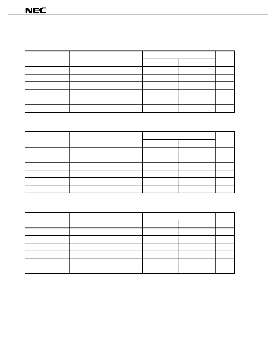
NOISE PARAMETERS
V
DS
= 2 V, I
DS
= 5 mA
opt
Frequency (GHz)
NF
min
(dB)
Ga (dB)
MAG.
ANG. (deg)
Rn/50
0.9
0.41
21.1
0.65
25.1
0.18
1.0
0.42
20.3
0.63
27.2
0.18
1.5
0.48
16.9
0.55
42.4
0.17
1.9
0.54
15.0
0.48
58.0
0.16
2.0
0.55
14.7
0.46
62.1
0.15
2.5
0.62
13.4
0.38
81.3
0.13
V
DS
= 2 V, I
DS
= 10 mA
opt
Frequency (GHz)
NF
min
(dB)
Ga (dB)
MAG.
ANG. (deg)
Rn/50
0.9
0.37
22.0
0.59
29.2
0.13
1.0
0.38
21.8
0.50
38.0
0.12
1.5
0.44
17.6
0.50
39.6
0.12
1.9
0.49
15.6
0.38
45.1
0.11
2.0
0.50
15.5
0.39
54.4
0.11
2.5
0.56
13.9
0.38
70.3
0.10
V
DS
= 3 V, I
DS
= 5 mA
opt
Frequency (GHz)
NF
min
(dB)
Ga (dB)
MAG.
ANG. (deg)
Rn/50
0.9
0.41
21.8
0.67
24.9
0.18
1.0
0.42
20.8
0.65
26.9
0.18
1.5
0.48
16.9
0.54
42.1
0.17
1.9
0.54
14.8
0.47
57.8
0.16
2.0
0.55
14.4
0.45
61.8
0.15
2.5
0.62
13.3
0.38
80.7
0.13
Preliminary Data Sheet
13
NE38018
RECOMMENDED SOLDERING CONDITIONS
This product should be soldered under the following recommended conditions. For soldering methods and
conditions other than those recommended below, contact your NEC sales representative.
Soldering Method
Soldering Conditions
Recommended Condition
Symbol
Infrared Reflow
Package peak temperature: 230°C or below
Time: 30 seconds or less (at 210°C)
Count: 3, Exposure limit
Note
: None
IR30-00-3
VPS
Package peak temperature: 215°C or below
Time: 40 seconds or less (at 200°C)
Count: 3, Exposure limit
Note
: None
VP15-00-3
Wave Soldering
Soldering bath temperature: 260°C or below
Time: 10 seconds or less
Count: 1, Exposure limit
Note
: None
WS60-00-1
Partial Heating
Pin temperature: 230°C
Time: 10 seconds or less (per pin row)
Exposure limit
Note
: None
Note After opening the dry pack, keep it in a place below 25°C and 65% RH for the allowable storage period.
Caution
Do not use different soldering methods together (except for partial heating).
PRECAUTION
Avoid high static voltage and electric fields, because this device is Hetero Junction field
effect transistor with shottky barrier gate.
Preliminary Data Sheet

14
NE38018
[MEMO]
Preliminary Data Sheet

15
NE38018
[MEMO]
Preliminary Data Sheet

NE38018
Caution
The Great Care must be taken in dealing with the devices in this guide.
The reason is that the material of the devices is GaAs (Gallium Arsenide), which is
designated as harmful substance according to the law concerned.
Keep the law concerned and so on, especially in case of removal.
No part of this document may be copied or reproduced in any form or by any means without the prior written
consent of NEC Corporation. NEC Corporation assumes no responsibility for any errors which may appear in
this document.
NEC Corporation does not assume any liability for infringement of patents, copyrights or other intellectual property
rights of third parties by or arising from use of a device described herein or any other liability arising from use
of such device. No license, either express, implied or otherwise, is granted under any patents, copyrights or other
intellectual property rights of NEC Corporation or others.
While NEC Corporation has been making continuous effort to enhance the reliability of its semiconductor devices,
the possibility of defects cannot be eliminated entirely. To minimize risks of damage or injury to persons or
property arising from a defect in an NEC semiconductor device, customers must incorporate sufficient safety
measures in its design, such as redundancy, fire-containment, and anti-failure features.
NEC devices are classified into the following three quality grades:
"Standard", "Special", and "Specific". The Specific quality grade applies only to devices developed based on a
customer designated "quality assurance program" for a specific application. The recommended applications of
a device depend on its quality grade, as indicated below. Customers must check the quality grade of each device
before using it in a particular application.
Standard: Computers, office equipment, communications equipment, test and measurement equipment,
audio and visual equipment, home electronic appliances, machine tools, personal electronic
equipment and industrial robots
Special: Transportation equipment (automobiles, trains, ships, etc.), traffic control systems, anti-disaster
systems, anti-crime systems, safety equipment and medical equipment (not specifically designed
for life support)
Specific: Aircrafts, aerospace equipment, submersible repeaters, nuclear reactor control systems, life
support systems or medical equipment for life support, etc.
The quality grade of NEC devices is "Standard" unless otherwise specified in NEC's Data Sheets or Data Books.
If customers intend to use NEC devices for applications other than those specified for Standard quality grade,
they should contact an NEC sales representative in advance.
Anti-radioactive design is not implemented in this product.
M4 96. 5
Document Outline