DATA S H E E T
SVS SERIES
SOLID TANTALUM CAPACITOR
Document No. EC0062EJ6V0DS00 (6th edition)
Date Published February 1998 M
Printed in Japan
The SVS series is a line-up of high performance ultra miniaturized tantalum chip capacitors.
The case dimensions are 2.0 mm
◊
1.25 mm
◊
1.2 mm as shown below.
FEATURES
TM The smallest molded chip tantalum capacitor (half size of the EIA standard A case)
TM Available up to 10
µ
F with case dimension of 2.0 mm
◊
1.25 mm
◊
1.2 mm (case code P)
APPLICATIONS
TM Portable stereos
TM VCR cameras
TM Hearing aids
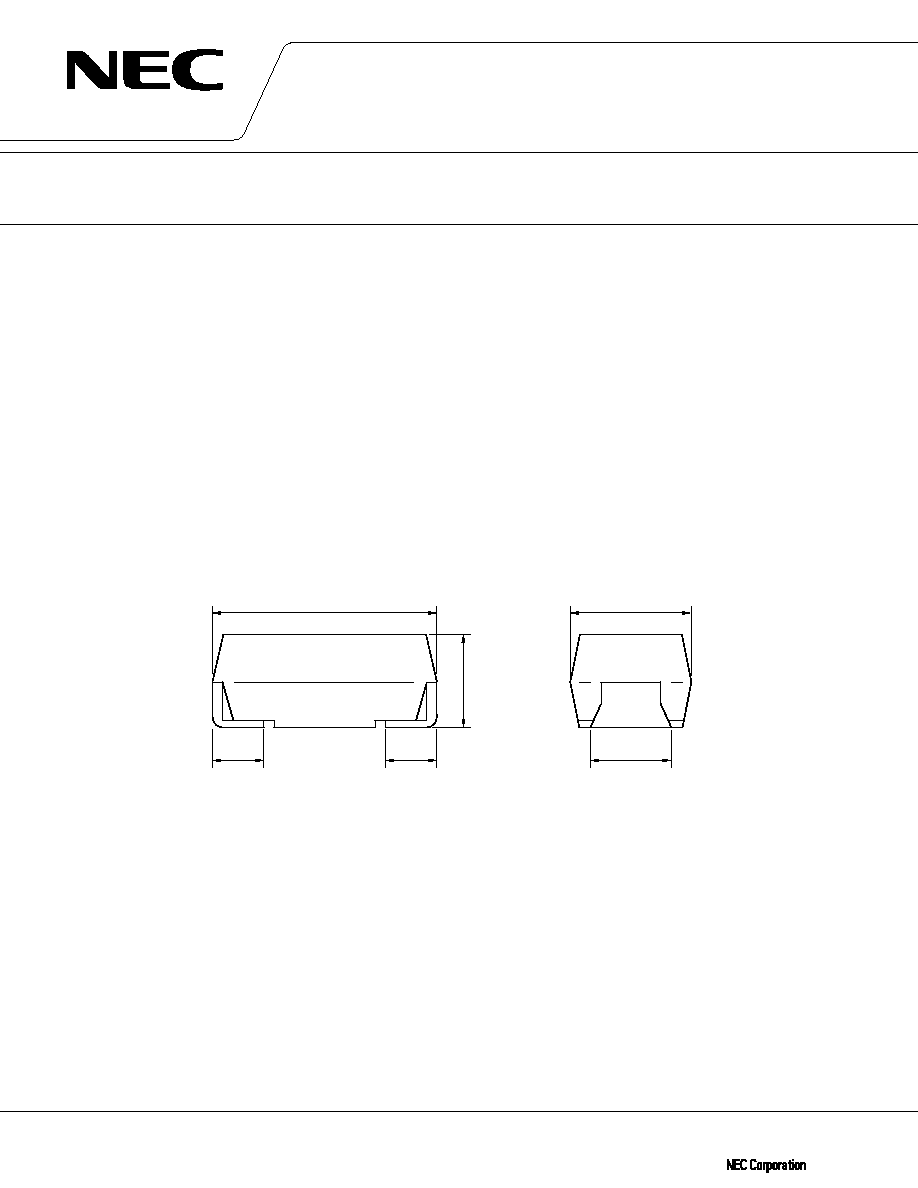
DIMENSIONS
Surface mount resin molded, Ultra miniaturized chip
©
1992(1996)
1.25
±
0.2
2.0
±
0.2
1.2 max.
(Unit : mm)
0.9
±
0 . 1
0.5
±
0 . 2
0.5
±
0 . 2
The information in this document is subject to change without notice.
2
SVS SERIES
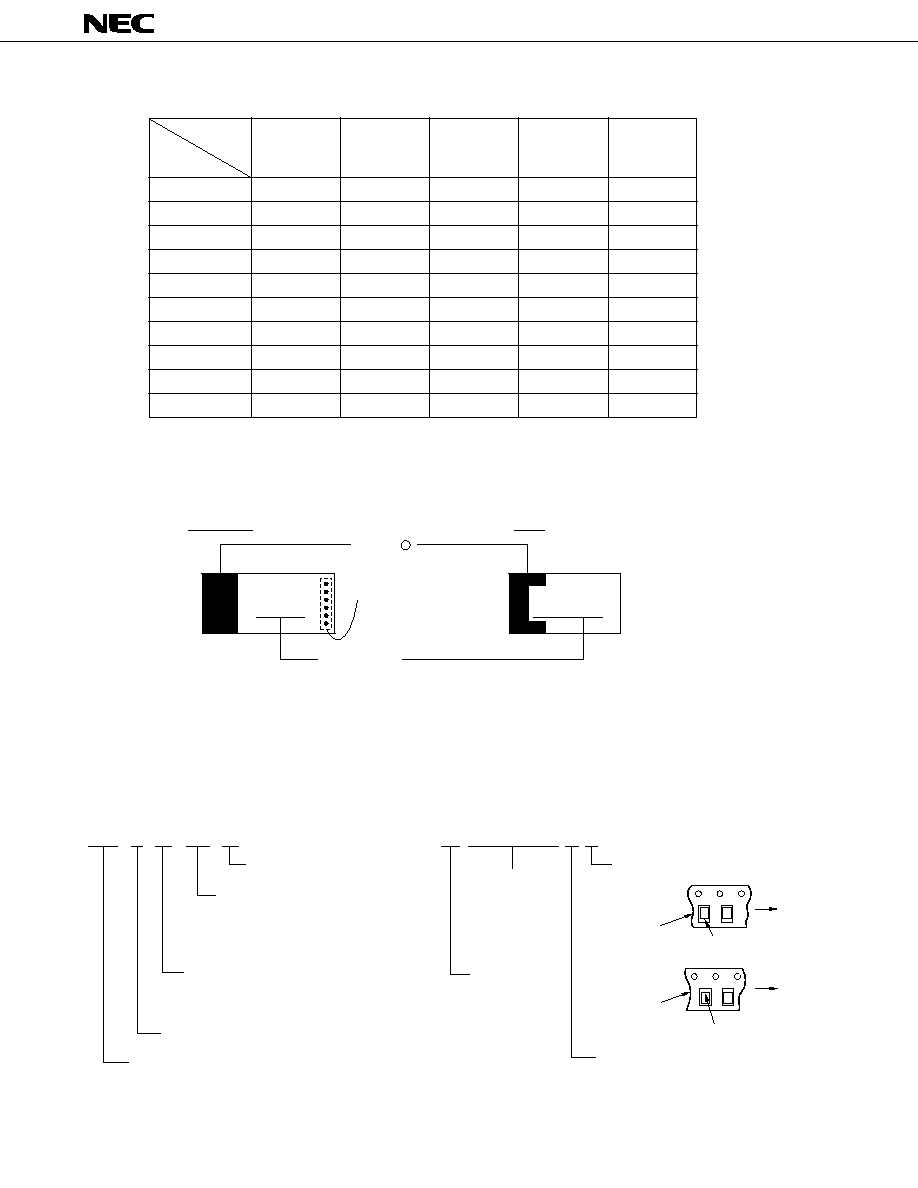
PRODUCT LINE-UP AND MARKING CODE
2.5
4
6.3
10
16
0.33
CN
0.47
CS
0.68
AW
CW
1
JA
AA
CA
1.5
GE
JE
AE
2.2
eJ
GJ
JJ
AJ
3.3
eN
GN
JN
AN
4.7
eS
GS
JS
6.8
eW
GW
JW
10
7eA
7GA
7JA
U
R
(Vdc)
Capacitance
(
µ
F)
U
R
: Rated voltage
PART NUMBER SYSTEM
[BULK]
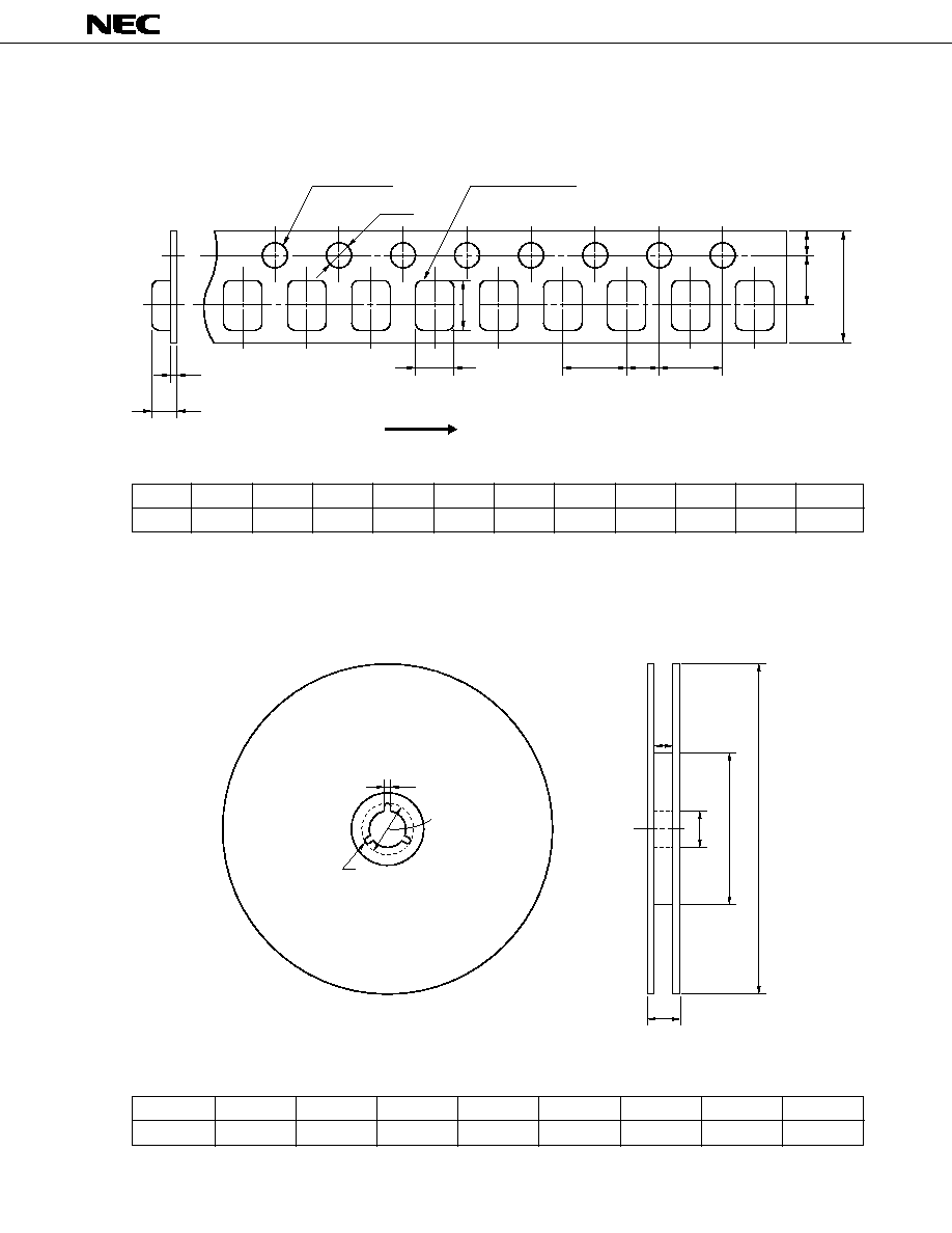
[TAPE & REEL]
Marking detail
SVS P 0J 105 M
TE SVSP0J105M 8 R
Polarity mark
Polarity mark
Feed direction
Tape
Tape
R : (Standard)
Orientation
L : (Non-Standard)
Orientation
Feed direction
Capacitance tolerance
±
20%
Packing orientation
Tape and reel
Tape width 8 mm
Part number of bulk
(see left)
Capacitance code in pF
First two digits represent significant
figures. Third digit specifies number
of zeros to follow.
Rated voltage
0E : 2.5 V, 0G : 4 V, 0J : 6.3 V
1A : 10 V, 1C : 16 V
Case code
SVS series
J A
Production date code
(indicated by dots)
Marking code
(corresponding to rated
voltage and capacitance)
Polarity
Implement date code on trial.
+
up to 6.8 F
µ
10 F
µ
7 J A
4
SVS SERIES
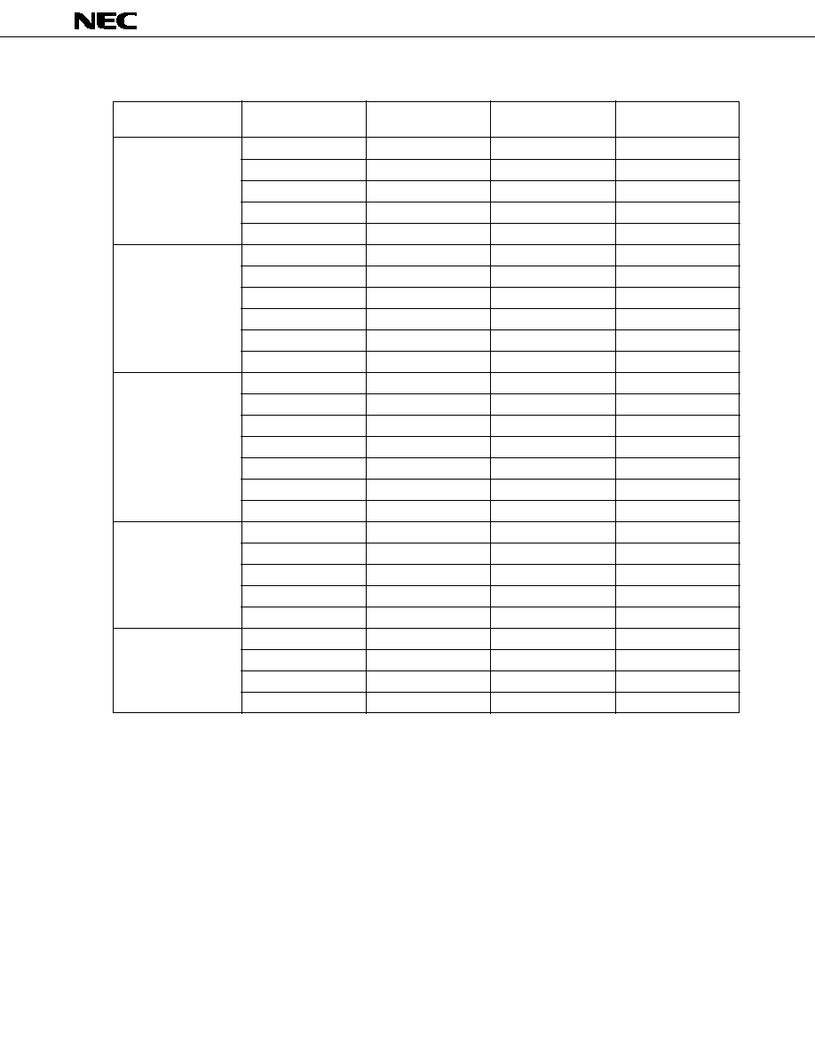
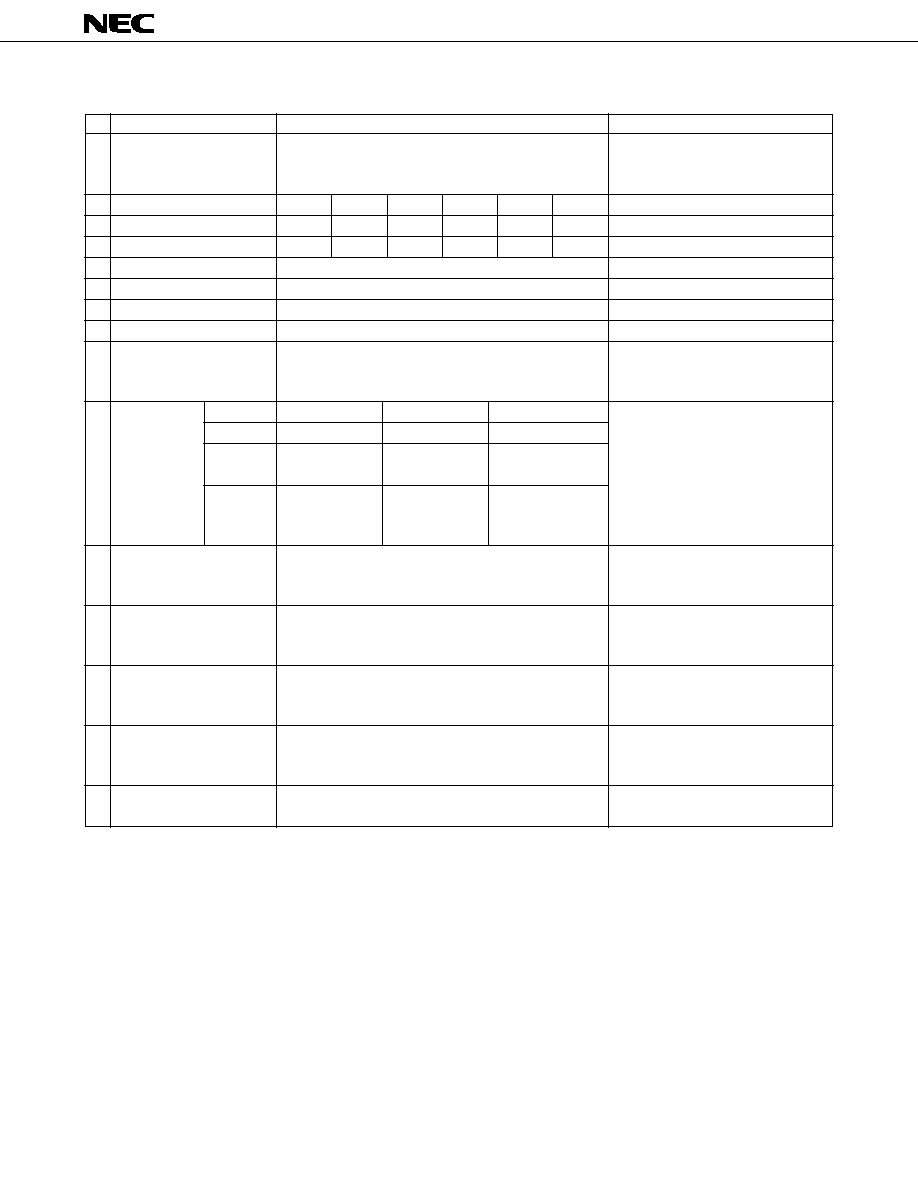
SPECIFICATIONS
No.
Items
1
Operating Temp. Range
2
Rated Voltage
3
Surge Voltage
4
Derated Voltage
5
Capacitance Range
6
Capacitance Tolerance
7
Leakage Current
8
Tangent of loss angle
9
Surge Voltage Resistance
Temp.
C /C
Tangent of
loss angle
Leakage
Current
11
Rapid change of temperature
12
Resistance to soldering
13
Damp Heat (Steady state)
14
Endurance
15
Failure Rate
Specifications
≠55 to +125∞C
2.5
4
6.3
10
16
Vdc
3.3
5.2
8
13
20
Vdc
1.6
2.5
4
6.3
10
Vdc
0.33 to 10
µ
F
±
20%
0.5
µ
A max.
0.1 max. / 0.2 max. (Refer to ratings)
C /C
:
±
20%
Tangent of loss angle : Initial requirement
Leakage Current
: Initial requirement
≠55∞C
+85∞C
+125∞C
%
%
%
150% of initial
Initial
150%of initial
requirement
requirement
requirement
0.1 CV or 5
µ
A
0.125 CV or 6.25
µ
A
≠≠
whichever is
whichever is
greater
greater
C /C
:
±
20%
Tangent of loss angle : Initial requirement
Leakage Current
: Initial requirement
C /C
:
±
20%
Tangent of loss angle : Initial requirement
Leakage Current
: Initial requirement
C /C
:
±
20%
Tangent of loss angle : 150% of Intial requirement
Leakage Current
: Initial requirement
C /C
:
±
20%
Tangent of loss angle : Initial requirement
Leakage Current
: 200% of Initial requirement
0
= 1% / 1 000 h
Test Conditions
Over 85∞C, applied voltage shall be derated
on the basis of the Derated Voltage at
125∞C specified in this table item no.4.
up to 85∞C
up to 85∞C
at 125∞C
at 120 Hz
at 120 Hz
5 min. after rated voltage applied
at 25∞C, 120 Hz
at 85∞C
Surge voltage for 30 sec. (Rs = 1 k
)
Discharge for 5 min. 30 sec.
1 000 cycles
Step1 : +25∞C
Step2 : ≠55∞C
Step3 : +25∞C
Step4 : +85∞C
Step5 : +125∞C
Step6 : +25∞C
IEC68-2-14 Test N and IEC68-2-33
Guidance
≠55 to +125∞C
5 cycles
IEC68-2-58 Test Td
Fully immersion to solder at 260∞C for
5 sec
IEC68-2-3 Test Ca
at 40∞C, 90 to 95% RH, for 500H
at 85∞C & 125∞C (Derated Voltage),
rated voltage applied for 2 000 H
at 85∞C & 125∞C (Derated Voltage),
rated voltage applied for 1 000 H
0
≠ 20
+20
0
+20
0
10
C /C : Capacitance change ratio
Characteris-
tics at high
and low
temperature