The
µ
PC1892 is a specific IC to reproduce surround sound by using phase shifters and a signal matrix.
The
µ
PC1892 provides wide sound with two speakers, and rich stereophonic sound with three speakers.
In case of stereo signal, the
µ
PC1892 has the movie mode to reproduce sense of immediacy (for movie) and the music mode
to emphasize vocal sound (for music), and it has the simulated mode to make monaural signal into wide deep sound. The modes
can be selected freely by using 2-bit parallel control pins.
In addition to this function reproducing surround sound, the
µ
PC1892 has a general sound processor that has volume, balance,
bass and treble control. So it is capable of reducing installation area.
All functions for processing signals of base band sound are provided on one chip.
FEATURES
∑ Three surround modes are available: movie, music and simulated
∑ Built in volume and balance control (All control voltage: 0 V to 5 V)
∑ Built in tone control (bass, treble) (All control voltage: 0 V to 5 V)
∑ Built in L+R output for woofer SP
∑
µ
PC1892CT-02: The volume and balance attenuation are bigger than
µ
PC1892CT.
APPLICATION
∑ TV
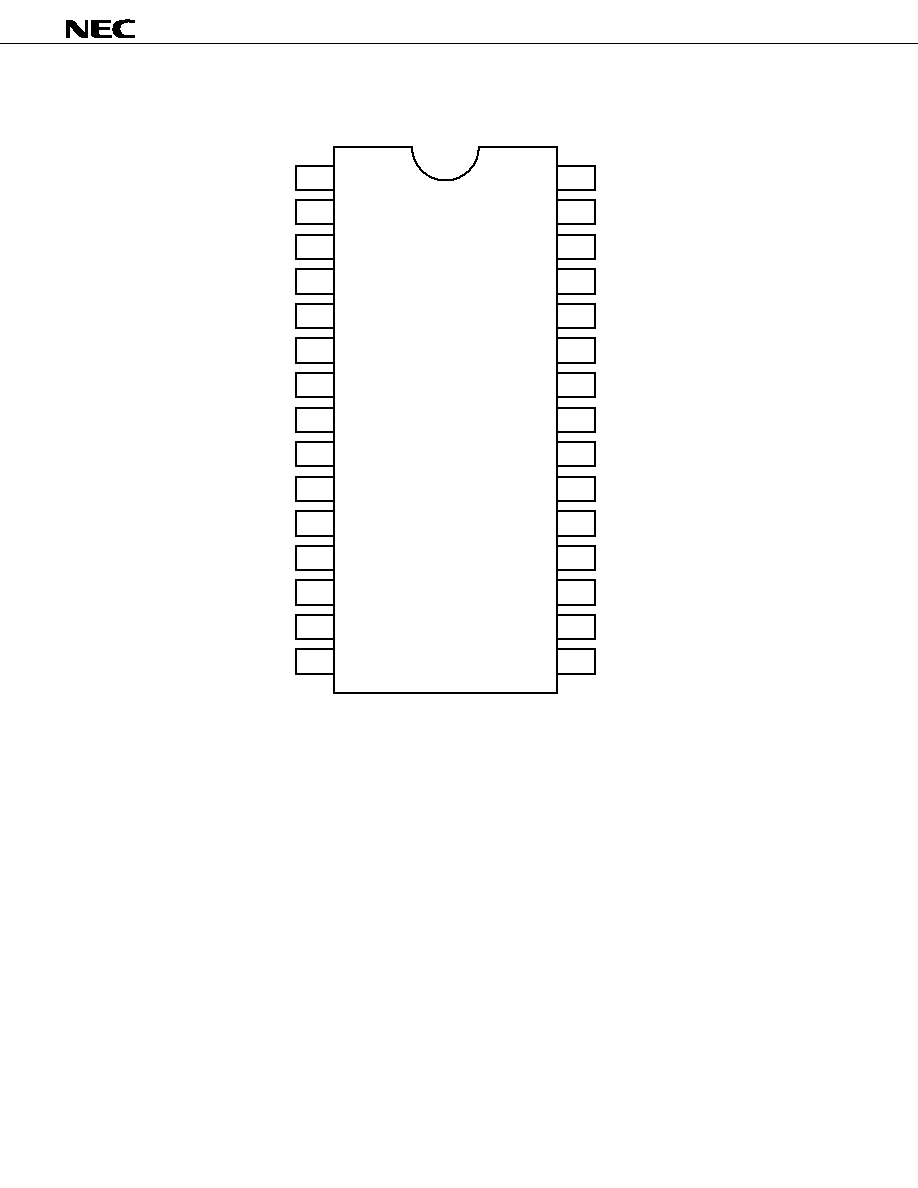
ORDERING INFORMATION
Part Number
Package
µ
PC1892CT
30-pin plastic shrink DIP (400 mil)
µ
PC1892CT-02
30-pin plastic shrink DIP (400 mil)
©
1991, 1992, 1995
DATA SHEET
MATRIX SURROUND SOUND PROCESSOR
WITH SOUND PROCESSOR
µ
PC1892
Bipolar Analog Integrated Circuit
Document No. S10650EJ3V0DS00 (3rd edition)
(Previous No. ID-2902)
Date Published October 1995 P
Printed in Japan
The information in this document is subject to change without notice.
µ
PC1892
2
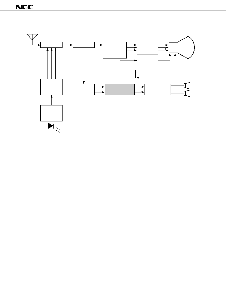
SYSTEM BLOCK DIAGRAM (TV)
Digital tuning
controller
PD17002
µ
PD17052
µ
PD17053
µ
PC1852
µ
L
R
µ
PC2800A
µ
PC2801A
µ
Tuner
PIF&SIF
Color
output
CRT
Vertical
output
Color, intensity
and defrecting
signal processor
Remote
control
reception
amplifier
PIN photo diode
Matrix surround
sound processor
US MTS
PC1310
PC1892
µ
PC1316C
µ
Power amplifier
CRT
µ
PC1892
3
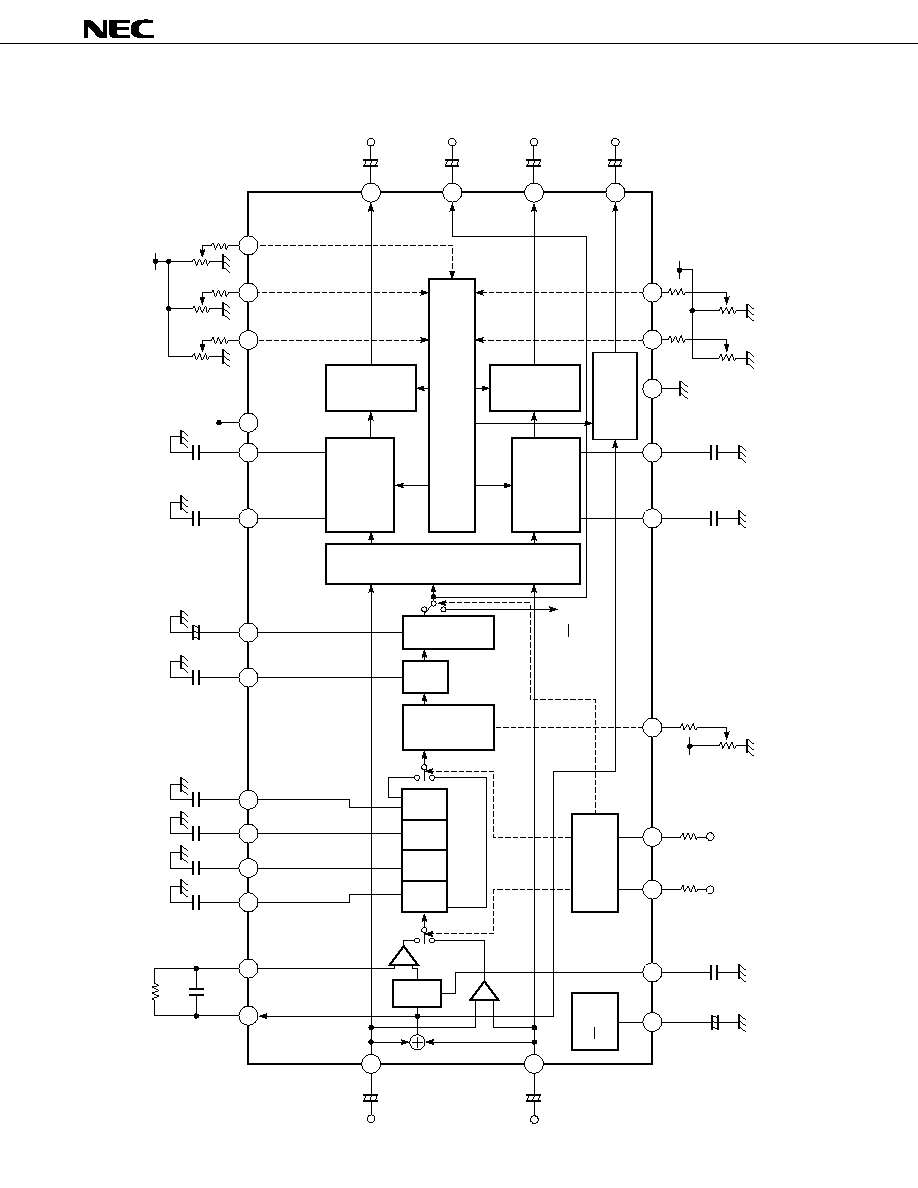
BLOCK DIAGRAM
HPF
28
29
2
3
4
5
30
22
21
1
20
19
18
14
9
12
26
25
13
16
DC CONTROL
17
15
11
10
23
8
7
27
24
MATRIX
EFFECT
CONTROL
Surround
OFFSET
ABSORPTION
VOLUME
BALANCE
CONTROL
VOLUME
BALANCE
CONTROL
VOLUME
CONTROL
TONE
(BASS, TREBLE)
CONTROL
TONE
(BASS, TREBLE)
CONTROL
6
820 k
2200 pF
FC1
FC2
FC3
FC4
0.022 F
0.1 F
0.082 F
µ
µ
1 F
+
µ
0.15 F
V
CC
+5 V
510
510
10 k
L OUTPUT
L+ (L≠R)
µ
VOLUME
CONTROL
BALANCE
CONTROL
L + R
VOLUME
CONTROL
10 k
510
10 k
+
4.7 F
R OUTPUT
R≠ (L≠R)
µ
+
4.7 F
L+R OUTPUT
L+R
µ
+
4.7 F
REAR OUTPUT
(L≠R)
(L≠R)
µ
+
4.7 F
6800 pF
µ
0.022 F 1000 pF
µ
µ
Note
Note
GND
+5 V
510
510
10 k
TREBLE
CONTROL
BASS
CONTROL
10 k
0.15 F
6800 pF
µ
+5 V
MS2
MS1
510
EFFECT
CONTROL
10 k
1 k
Music
OFF
L≠R
Movie/
Music
Simulated
≠
+
≠
+
Simulated/Movie
PS1
LPF
1
PS2 PS3 PS4
LPF
2
PHASE SHIFTER
1 k
V
CC
R
IN
MODE
CONTROL
+
680 pF
22 F
1
2
µ
+
22 F
µ
22 F
µ
L
IN
+
Note
Note
V
CC
1
2
Note Recommended Precision:
±
1 %
µ
PC1892
5
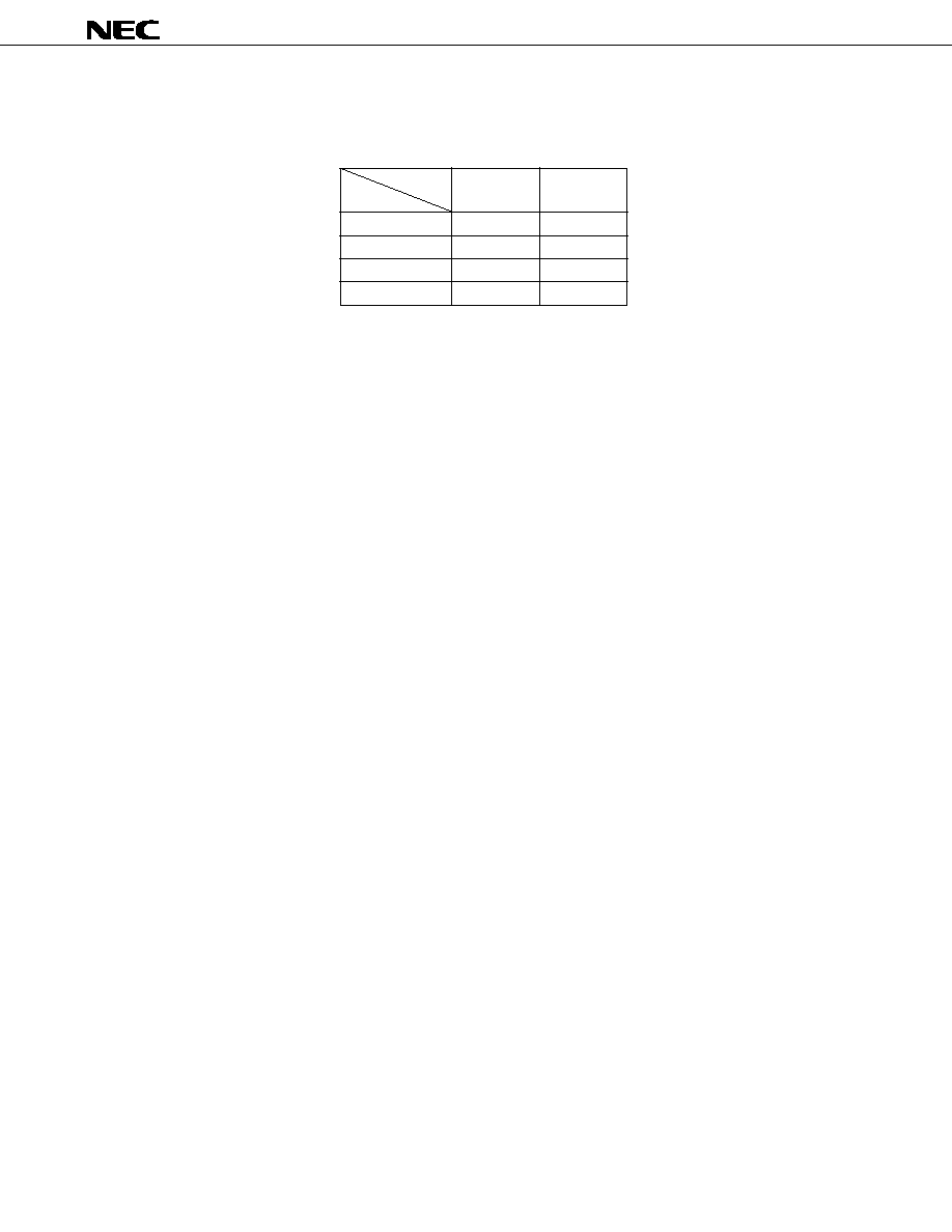
MODE SELECT CODE
Select among OFF, Movie, Music and Simulated mode by MS1 and MS2 (Pins 7 and 8).
Code
MS1
MS2
Mode
(Pin 7)
(Pin 8)
OFF
L
L
Music
H
L
Movie
L
H
Simulated
H
H
Cautions 1. In the case of changing surround mode and power ON/OFF, mute (approx. 200 ms) must be used for pop
noise reduction.
2. Insert resistors between mode select pins (pin 7, 8) and GND, between control pins (pin 16, 17, 18, 19, 20,
23) and GND.
3. Connect a electrolytic capacitor for power supply as close as possible to V
CC
(pin 1).
Remark
About "H" and "L", refer to RECOMMENDED OPERATING CONDITIONS.