 | –≠–ª–µ–∫—Ç—Ä–æ–Ω–Ω—ã–π –∫–æ–º–ø–æ–Ω–µ–Ω—Ç: UPD168103 | –°–∫–∞—á–∞—Ç—å:  PDF PDF  ZIP ZIP |
The information in this document is subject to change without notice. Before using this document, please
confirm that this is the latest version.
Not all products and/or types are available in every country. Please check with an NEC Electronics
sales representative for availability and additional information.
MOS INTEGRATED CIRCUIT
µ
PD168103
5-CHANNEL OPERATIONAL AMPLIFIER, IRIS DRIVER,
AND 4-CHANNEL H-BRIDGE DRIVER
DATA SHEET
Document No. S17332EJ1V0DS00 (1st edition)
Date Published February 2005 NS CP(K)
Printed in Japan
2004
DESCRIPTION
The
µ
PD168103 is the motor driver IC with IRIS control circuit, operational amplifier and 4-ch H-bridge output.
Smooth operation is possible for IRIS control with linear method.
The package is 48-pin thin type QFN and then it helps reduce the mounting area and height.
The
µ
PD168103 is suitable for the lens drive of a camcorder, DSC, etc.
FEATURES
∑ 5-ch H-bridge circuits employing power MOS FET
∑ Low-voltage driving
LV
DD
= 2.7 to 3.6 V, AV
DD
= 4.5 to 5.5 V, V
M12
= V
M34
= V
SHUTTER
= V
IRIS
= 2.7 to 5.5 V
∑ Output on-state resistance: 2.0 TYP., 3.0 MAX. (4-ch H-bridge block, sum of top and bottom stage, V
M
= 5 V)
∑ PWM output (ch1 to ch4)
∑ Output current
DC current:
±0.3 A/ch (when each channel is used independently)
Peak current:
±0.7 A/ch (when each channel is used independently)
∑ 3-ch general-purpose operational amplifier
Input offset voltage:
±5 mV
Input voltage range: 0 to AV
DD
- 1.5 V
Output voltage range: 0.2 to AV
DD
- 0.2 V
∑ 1-ch current sink amplifier
Output current: 5 mA
∑ 1-ch 1/2V
DD
output amplifier
∑ IRIS driver block supporting linear driving
∑ Pre-driver amplifier of the IRIS driver block
∑ Undervoltage lockout circuit
Output circuit and amplifier stop at LV
DD
= 1.7 V TYP. or less.
∑ Overheat protection circuit
Operates at 150∞C or more and shuts down the output circuit.
∑ Mounted on 48-pin plastic WQFN (7 x 7)
APPLICATIONS
Lens motor driving for DVC and DSC, etc.
ORDERING INFORMATION
Part Number
Package
Marking
Packing Type
µ
PD168103K9-5B4-A
Note
48-pin plastic WQFN (7 x 7)
D168103
∑ Tray stuffing
∑ Dry pack
Note Pb-free (This product does not contain Pb in external electrode and other parts.)
Data Sheet S17332EJ1V0DS
2
µ
PD168103
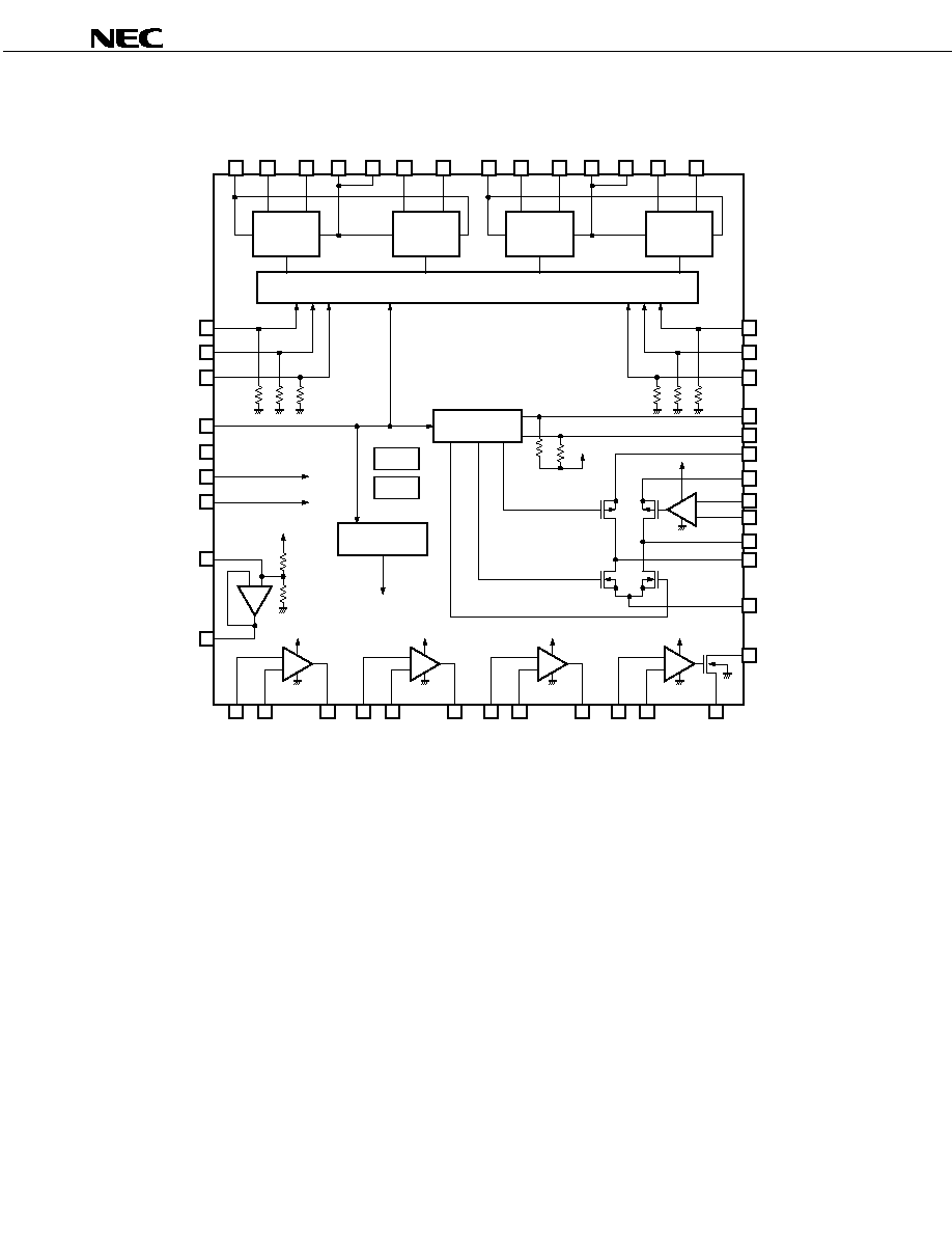
1. BLOCK DIAGRAM
OUT
1B
EN
12
OUT
1A
OUT
1
OUT
2A
OUT
2B
V
M12
PGND12
IN
1P
IN
1M
H-bridge Control
Amp. Control
TSD
UVLO
H-bridge
1
H-bridge
2
IN
1
IN
2
EN
34
IN
3
IN
4
GND
LV
DD
LV
DD
AV
DD
1/2LV
DD
AV
DD
OUT
3B
OUT
3A
OUT
4A
OUT
4B
V
M34
PGND34
H-bridge
3
H-bridge
4
LV
DD
RESETB
IR
IN1
OUT
4D
PGND5
Logic power
IN
REF
OUT
REF
Analog power
Amp.
ON/OFF
control
+
-
- +
AMP0
AMP1
OUT
2
IN
2P
IN
2M
AV
DD
+
-
AMP2
OUT
3
IN
3P
IN
3M
AV
DD
+
-
AMP3
OUT
4S
IN
4P
IN
4M
AV
DD
+
-
AMP4
AV
DD
GND
+
-
AMP5
IR
IN2
IN
IRP
IN
IRM
OUT
IRP
OUT
IRM
V
SUTTER
V
IRIS
IRIS Control
44
42
46
48
45
43
47
17
19
15
13
16
18
14
7
8
9
10
21
29
11
33
32
30
28
27
31
41
39
40
38
36
37
26
24
25
20
23
22
4
5
6
2
1
12
3
34
35
Cautions 1. P in pin name means plus, and M in pin name means minus.
2. A pull-down resistor (50 to 200 k
) is connected to the logic input pins (EN
12
, EN
34
, IN
1
, IN
2
, IN
3
,
and IN
4
). A pull-up resistor (50 to 200 k
) is connected to the IR
IN1
and IR
IN2
pins.

Data Sheet S17332EJ1V0DS
3
µ
PD168103
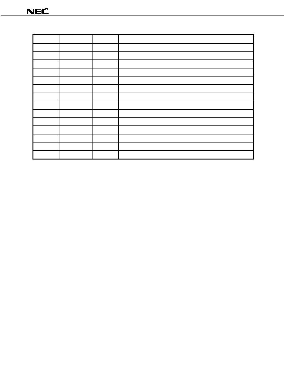
2. PIN FUNCTIONS
(1/2)
Pin No.
Pin Name
I/O
Function
1 LV
DD
-
Logic power supply voltage pin
2 GND
-
Logic and analog GND pin
3
RESETB
Input
Reset input pin
4 EN
12
Input
ch1 and ch2 output control input pin
5 IN
1
Input
ch1 input pin
6 IN
2
Input
ch2 input pin
7 EN
34
Input
ch3 and ch4 output control input pin
8 IN
3
Input
ch3 input pin
9 IN
4
Input
ch4 input pin
10 IR
IN1
Input
IRIS control logic input pin 1
11 IR
IN2
Input
IRIS control logic input pin 2
12 AV
DD
-
Analog power supply voltage pin
13 OUT
4B
Output
ch4 output pin B
14 PGND34
-
ch3 and ch4 GND pin
15 OUT
4A
Output
ch4 output pin A
16 VM
34
-
ch3 and ch4 power supply voltage pin
17 OUT
3B
Output
ch3 output pin B
18 PGND34
-
ch3 and ch4 GND pin
19 OUT
3A
Output
ch3 output pin A
20 OUT
4S
Output
Amplifier 4 (AMP4) source output pin (source)
21 OUT
4D
Output
Amplifier 4 (AMP4) drain output pin (sink)
22 IN
4M
Input
Amplifier 4 (AMP4) minus input pin
23 IN
4P
Input
Amplifier 4 (AMP4) plus input pin
24 IN
3P
Input
Amplifier 3 (AMP3) plus input pin
25 IN
3M
Input
Amplifier 3 (AMP3) minus input pin
26 OUT
3
Output
Amplifier 3 (AMP3) output pin
27 V
SHUTTER
-
Shutter (ON/OFF) power supply voltage pin
28 OUT
IRM
Output
IRIS minus output pin
29 PGND5
-
IRIS and shutter GND pin
30 OUT
IRP
Output
IRIS plus output pin
31 V
IRIS
-
IRIS (linear) power supply voltage pin
32 IN
IRM
Input
IRIS linear control (AMP5) minus input pin
33 IN
IRP
Input
IRIS linear control (AMP5) plus input pin
34 IN
REF
Input
1/2AV
DD
amplifier (AMP0) input pin (for capacitor connection)
Data Sheet S17332EJ1V0DS
4
µ
PD168103
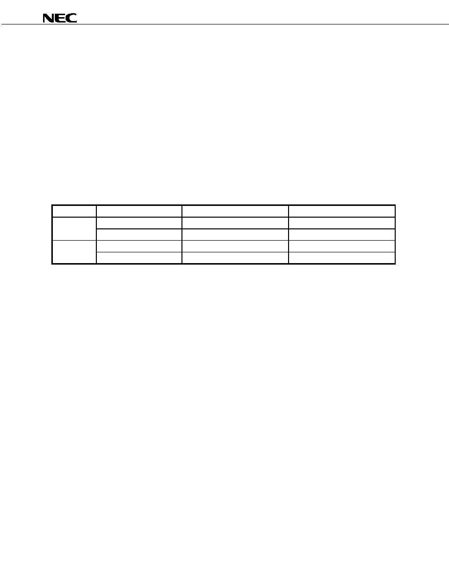
(2/2)
Pin No.
Pin Name
I/O
Function
35 OUT
REF
Output
1/2AV
DD
amplifier (AMP0) output pin
36 IN
2P
Input
Amplifier 2 (AMP2) plus input pin
37 IN
2M
Input
Amplifier 2 (AMP2) minus input pin
38 OUT
2
Output
Amplifier 2 (AMP2) output pin
39 IN
1P
Input
Amplifier 1 (AMP1) plus input pin
40 IN
1M
Input
Amplifier 1 (AMP1) minus input pin
41 OUT
1
Output
Amplifier 1 (AMP1) output pin
42 OUT
1A
Output
ch1 output pin A
43 PGND12
-
ch1 and ch2 GND pin
44 OUT
1B
Output
ch1 output pin B
45 V
M12
-
ch1 and ch2 power supply voltage pin
46 OUT
2A
Output
ch2 output pin A
47 PGND12
-
ch1 and ch2 GND pin
48 OUT
2B
Output
ch2 output pin B
Data Sheet S17332EJ1V0DS
5
µ
PD168103
3. FUNCTION OPERATION TABLE
3.1 Reset Function
The internal circuit is shut off and the circuit current is kept to 1
µ
A MAX. when the RESETB pin is made L (reset
status). In this status, the output pin goes into a Hi-Z (High impedance) state. Set the RESETB pin H for normal
usage.
Remark H: High level, L: Low level
3.2 Stepping Motor Driving Block
Table 3
-1. I/O Truth Table of the Stepping Motor Driving Block
EN
12
, EN
34
IN
1
, IN
2
, IN
3
, IN
4
OUT
1A
, OUT
2A
, OUT
3A
, OUT
4A
OUT
1B
, OUT
2B
, OUT
3B
, OUT
4B
H L
H
L
H
L
H
L L
Hi-Z
Hi-Z
H
Hi-Z
Hi-Z