Document Outline
- Cover
- FEATURES
- ORDERING INFORMATION
- PIN CONFIGURATION (TOP VIEW)
- CONTENTS
- 1. PIN FUNCTIONS
- 2. KEY MATRIX STRUCTURE
- 2.1 Placement of the Initial Setting Diode, Alternation, and Transistor Switch Matrixes
- 2.2 Switch Connection
- 2.3 Initial Setting Diode, Alternation, and Transistor Switch Matrix Connection
- 2.4 Momentary Key Matrix Placement
- 2.5 Momentary Key Matrix Connection
- 2.6 Description of the Key Matrixes
- 2.6.1 Initial setting diode matrixes
- 2.6.2 Alternation or transistor switch
- 2.6.3 Momentary keys
- 3. ALARM FUNCTION
- 3.1 Overview of the Alarm Function
- 3.2 Setting Alarm Mode
- 4. MODE TRANSITION
- 5. DISPLAY
- 5.1 LCD Panel
- 5.2 Character Style
- 5.3 Examples of Display
- 5.4 LCD Assignment
- 5.5 Pin Assignment of the LCD Controller/Driver (uPD7225)
- 5.6 Description of Display
- 6. REMOTE CONTROL FUNCTION
- 6.1 Remote-Controller Key Placement (When the uPD6121G Is Used)
- 6.2 Remote-Controller Keys
- 6.3 Remote-Controller Data Codes
- 6.4 Example of a Remote-Controller Circuit Using the uPD6121G-001
- 6.5 Example of a Remote-Controller Preamplifier Circuit Using the uPC2800HA
- 7. MUTE OUTPUT TIMING CHARTS
- 7.1 Radio Mute (RDMUTE# Pin) Output Timing Charts
- 7.2 Radio Mute (RDMUTE# Pin) and Audio Mute (AMUTE# Pin) Output Timing Charts
- 8. PIN I/O CIRCUITS
- 9. SAMPLE APPLICATION CIRCUITS
- 10. ELECTRICAL CHARACTERISTICS (PRELIMINARY)
- 11. PACKAGE DRAWING
- 12. RECOMMENDED SOLDERING CONDITIONS
- APPENDIX COMMUNICATION WITH ELECTRONIC VOLUME CONTROL IC (I2 C BUS INTERFACE)
PLL FREQUENCY SYNTHESIZER AND CONTROLLER
FOR FM/MW/LW TUNER (AUTOMOBILE APPLICATION)
PRELIMINARY DATA SHEET
MOS INTEGRATED CIRCUIT
µ
PD17012GF-058
Document No. U12506EJ1V0DS00 (1st edition)
Date Published July 1997 J
Printed in Japan
©
1990
The
µ
PD17012GF-058 is a CMOS LSI chip designed for use in FM/MW/LW tuners utilizing a PLL frequency
synthesizer design for worldwide applications.
The device incorporates a PLL frequency synthesizer controller, prescaler, and frequency counter. The device
enables detachable stereo systems, and is ideal for use in electronic volume control circuits for automobile
applications, high-performance FM/MW/LW tuners with a clock, and similar applications where compact dimensions
are essential.
FEATURES
∑
Capable of receiving broadcasts from stations in all of the world's FM and MW bands, as well as the European
LW band
∑
Applicable to AM up-conversion
∑
Many preset functions including manual tuning, auto-tuning (seek, scan), and preset memory scanning
∑
Independent preset memory with six buttons: up to 18 FM stations (six stations, each enabling the setting of FM1,
FM2, and FM3), up to 12 MW stations (six stations, each enabling the setting of MW1 and MW2), and up to six
LW stations
∑
Last channel memory for three FM stations, two MW stations, and one LW station
∑
ST (stereo) display (The ST display is also supported for the MW band.)
∑
Display and control output of MTL (METAL)
∑
Auto-preset memory function
∑
"
" (compact disc)/"
" (cassette tape) display
∑
LOUD (loudness) control output and display
∑
Clock function for 12-hour or 24-hour clock display
∑
Compatible with the external LCD controller/driver (
µ
PD7225)
∑
Built-in prescaler and frequency counter
∑
Remote-controller signal receiving function (when the
µ
PD6121 is used for transmitting signals)
∑
Detachable keys (or key section) and LCD panel
∑
Electronic volume control function (compatible with the I
2
C bus)
∑
Alarm function
ORDERING INFORMATION
Part number
Package
µ
PD17012GF-058-3BE
64-pin plastic QFP (14
◊
20 mm, 1.0 mm pitch)
1997
The information in this document is subject to change without notice.
µ
PD17012GF-058
2
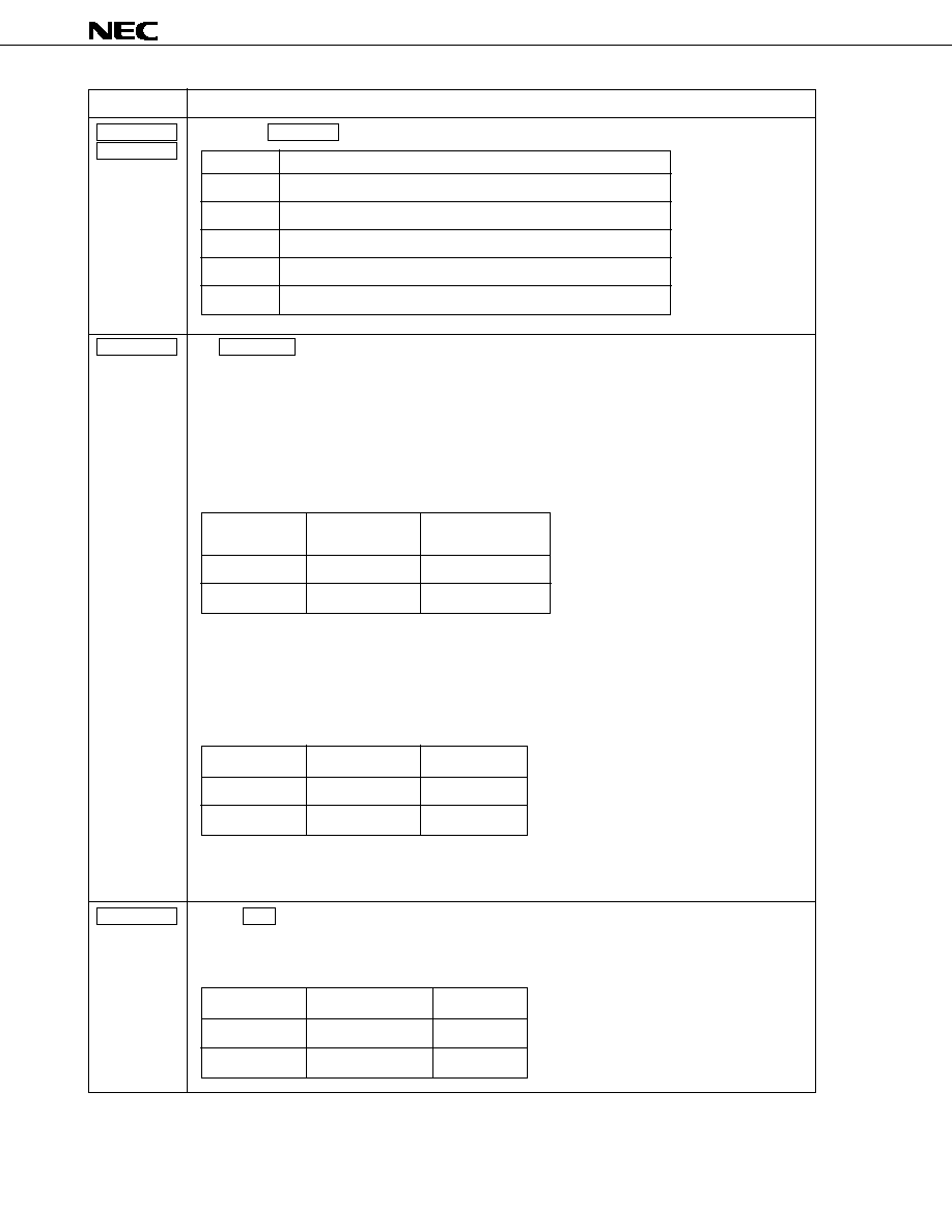
FUNCTION OVERVIEW
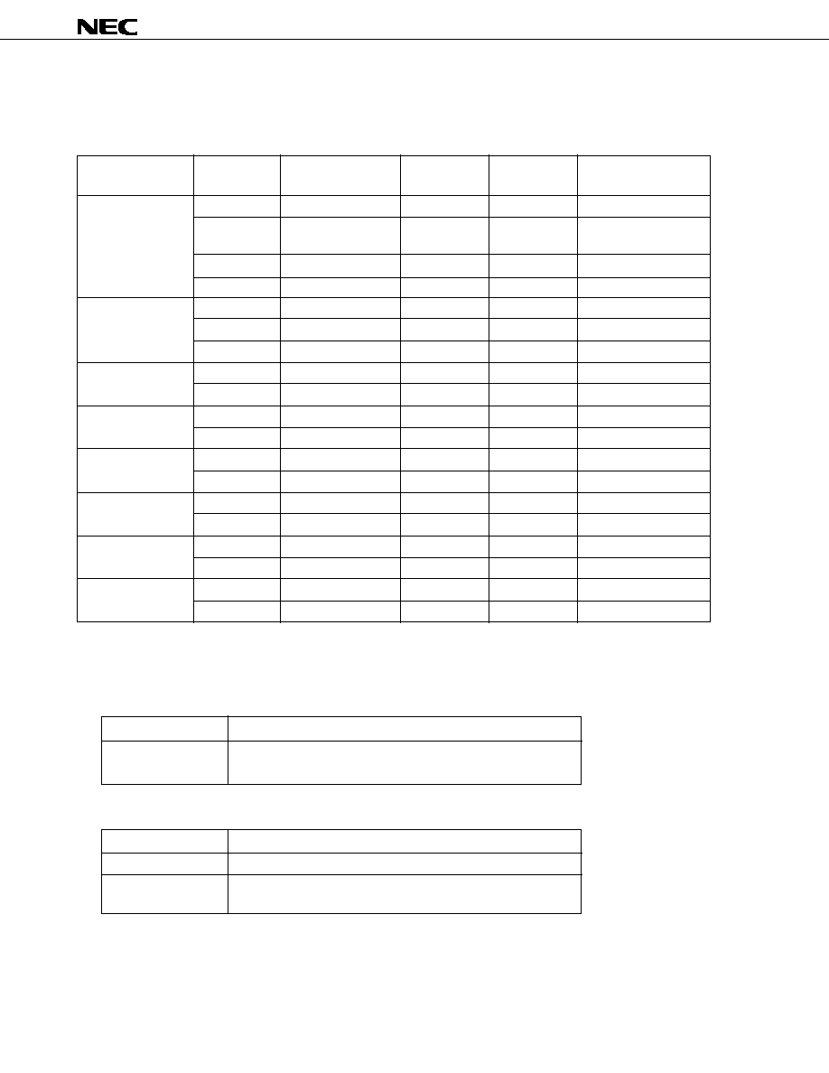
FREQUENCY TO BE RECEIVED, CHANNEL SEPARATION, REFERENCE FREQUENCY, AND INTERMEDIATE
FREQUENCY
RADIO FUNCTIONS
(1) Manual tuning
(2) Auto-tuning
(3) Preset memory scanning: Tunes to broadcasts of stations held in preset memory for five seconds each.
Function
Manual up
Manual down
Description
Carries out tuning in step-by-step or fast-forward mode.
Function
Seek up
Scan up
Scan down
Description
Detects a station and retains the frequency.
Tunes to broadcasts of different stations for five seconds each.
Eastern Europe
Western Europe
China
Australia, Middle
East
U.S.A. 1
U.S.A. 2
U.S.A. 3
Japan
65 - 74 MHz
87.5 - 108.0 MHz
522 - 1 620 kHz
144 - 290 kHz
87.5 - 108.0 MHz
522 - 1 620 kHz
144 - 290 kHz
87.0 - 108.0 MHz
531 - 1 602 kHz
87.5 - 108.0 MHz
531 - 1 602 kHz
87.5 - 108.0 MHz
530 - 1 620 kHz
87.5 - 107.9 MHz
530 - 1 620 kHz
87.5 - 107.9 MHz
530 - 1 710 kHz
76.0 - 90.0 MHz
522 - 1 629 kHz
10.7 MHz
10.7 MHz
450 kHz/+10.71 MHz
450 kHz/+10.71 MHz
10.7 MHz
450 kHz/+10.71 MHz
450 kHz/+10.71 MHz
10.7 MHz
450 kHz/+10.71 MHz
10.7 MHz
450 kHz/+10.71 MHz
10.7 MHz
450 kHz/+10.71 MHz
10.7 MHz
450 kHz/+10.71 MHz
10.7 MHz
450 kHz/+10.71 MHz
-10.7 MHz
450 kHz/+10.71 MHz
FM1
FM2
FM3
MW
LW
FM
MW
LW
FM
MW
FM
MW
FM
MW
FM
MW
FM
MW
FM
MW
50 kHz
50 kHz
9 kHz
1 kHz
50 kHz
9 kHz
1 kHz
50 kHz
9 kHz
100 kHz
9 kHz
100 kHz
10 kHz
200 kHz
10 kHz
200 kHz
10 kHz
100 kHz
9 kHz
25 kHz
25 kHz
9 kHz
1 kHz
25 kHz
9 kHz
1 kHz
25 kHz
9 kHz
25 kHz
9 kHz
25 kHz
10 kHz
25 kHz
10 kHz
25 kHz
10 kHz
25 kHz
9 kHz
Area
Reference
frequency
Intermediate
frequency
Channel
separation
Frequency to be
received
Band

µ
PD17012GF-058
3
(4) Preset memory
∑ FM band: FM1: Six stations, FM2: Six stations, FM3: Six stations
∑ MW band: MW1: Six stations, MW2: Six stations
∑ LW band: Six stations
(5) Last channel memory: One station each for FM1, FM2, FM3, MW1, MW2, LW
(6) LOC (local) control output and display (The auto local function can be selected.)
(7) ST (stereo) display function: Supported for the FM band. The display function is also supported for the MW band.
(A switching function is supported.)
(8) Auto-storage
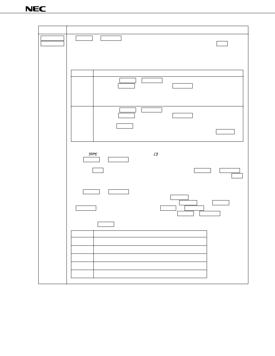
TAPE FUNCTIONS
(1) Tape running direction display: Can be blinked at 2.5 Hz in fast-forward mode
(2) MTL (METAL) control output and display
(3) "
" (cassette tape) display function
ELECTRONIC VOLUME CONTROL FUNCTIONS
(1) Volume/bass/treble/balance/fader function
(2) "
"/"
"/"
"/"
"/"
" display on the LCD panel
(3) Mute function (In the mute state, the entire panel display blinks.)
(4) Loudness function
(5) Four selectable gain levels (0 dB, 3.75 dB, 7.5 dB, or 11.25 dB)
CLOCK FUNCTIONS
(1) Selectable 12-hour clock display (with AM/PM indication) or 24-hour clock display
(2) Selectable colon (:) flashing (1 Hz)
(3) Capable of back-up with low current consumption (up to 10
µ
A) in no-clock mode
SECURITY FUNCTION
Enables of setting of the alarm function for security against car theft
OTHERS
(1) LOUD (loudness) control output and display: Common to radio, tape, and CD modes
(2) Key acknowledge (beep) output: Performed if a valid momentary key is on
(3) Display switching function and privileged display function
(4) "
" (compact disc) display
(5) Compatible with the external LCD controller/driver (
µ
PD7225)
(6) Remote-controller signal receiving function (when the
µ
PD6121 is used for transmitting signals)
(7) Detachable keys (or key section) and LCD panel

µ
PD17012GF-058
4
PIN CONFIGURATION (TOP VIEW)
64-pin plastic QFP (14
◊
20 mm, 1.0 mm pitch)
µ
PD17012GF-058-3BE
EVOL_SCK (P1A1)
EVOL_DA (P1A0)
EO
V
DD
1
VCOL
VCOH
CE
V
DD
2
SCK (P0A2)
SO (P0A1)
ALARMIN (P0A0)
FMIFC (P1B3)
AMIFC (P1B2)
KY-IN (ADC1/P1B1)
SD (ADC0/P1B0)
DSP1 (P0B3)
DSP2 (P0B2)
BEEP (P0B1)
IGNITION (P0B0)
51
50
49
48
47
46
45
44
43
42
41
40
39
38
37
36
35
34
33
64 63 62 61 60 59 58 57 56 55 54 53 52
20 21 22 23 24 25 26 27 28 29 30 31 32
1
2
3
4
5
6
7
8
9
10
11
12
13
14
15
16
17
18
19
KS6 (PYA6)
KS7 (PYA7)
KS8 (PYA8)
KS9 (PYA9)
MODE1 (PYA10)
MODE2 (PYA11)
CDOUT (PYA12)
MTL (PYA13)
IC (PYA14)
IC (PYA15)
LCD CS (P2E0)
IC (P2F0)
ILLUMI (P2G0)
POUT (P2H0)
IC (COM0)
IC (COM1)
IC (COM2)
BAND2 (P1D0)
BAND1 (P1D1)
AGCC (P1C3)
LOC (P1C2)
AMUTE (P1C1)
RDMUTE (P1C0)
X
OUT
X
IN
GND
ALARMOUT (P0C3)
KEYS2 (P0C2)
KEYS1 (P0C1)
KEYS0 (P0C0)
LOUD (P1D3)
POWER (P1D2)
REM (INT)
MONO (P1A2)
K0 (P0D0)
K1 (P0D1)
K2 (P0D2)
K3 (P0D3)
GND
KS0 (PYA0)
KS1 (PYA1)
KS2 (PYA2)
KS3 (PYA3)
KS4 (PYA4)
KS5 (PYA5)
Remarks 1. The pin names enclosed in parentheses are those for the
µ
PD17012GF-
◊◊◊
-3BE.
2. IC indicates that the pin is internally connected. Leave the IC pins open.

µ
PD17012GF-058
5
CONTENTS
1.
PIN FUNCTIONS ........................................................................................................................
7
2.
KEY MATRIX STRUCTURE ......................................................................................................
14
2.1
Placement of the Initial Setting Diode, Alternation, and Transistor Switch Matrixes ...........
14
2.2
Switch Connection ...........................................................................................................................
14
2.3
Initial Setting Diode, Alternation, and Transistor Switch Matrix Connection .........................
15
2.4
Momentary Key Matrix Placement .................................................................................................
16
2.5
Momentary Key Matrix Connection ...............................................................................................
16
2.6
Description of the Key Matrixes ....................................................................................................
17
2.6.1
Initial setting diode matrixes ............................................................................................
17
2.6.2
Alternation or transistor switch .......................................................................................
28
2.6.3
Momentary keys .................................................................................................................
29
3.
ALARM FUNCTION ....................................................................................................................
52
3.1
Overview of the Alarm Function ....................................................................................................
52
3.2
Setting Alarm Mode .........................................................................................................................
53
4.
MODE TRANSITION ..................................................................................................................
59
5.
DISPLAY .....................................................................................................................................
66
5.1
LCD Panel .........................................................................................................................................
66
5.2
Character Style .................................................................................................................................
66
5.3
Examples of Display ........................................................................................................................
66
5.4
LCD Assignment ..............................................................................................................................
67
5.5
Pin Assignment of the LCD Controller/Driver (
µ
PD7225) ..........................................................
67
5.6
Description of Display .....................................................................................................................
68
6.
REMOTE CONTROL FUNCTION ..............................................................................................
70
6.1
Remote-Controller Key Placement (When the
µ
PD6121G Is Used) ..........................................
70
6.2
Remote-Controller Keys ..................................................................................................................
71
6.3
Remote-Controller Data Codes ......................................................................................................
71
6.4
Example of a Remote-Controller Circuit Using the
µ
PD6121G-001 ..........................................
72
6.5
Example of a Remote-Controller Preamplifier Circuit Using the
µ
PC2800HA ........................
72
7.
MUTE OUTPUT TIMING CHARTS ............................................................................................
73
7.1
Radio Mute (RDMUTE Pin) Output Timing Charts ......................................................................
73
7.2
Radio Mute (RDMUTE Pin) and Audio Mute (AMUTE Pin) Output Timing Charts ..................
76
8.
PIN I/O CIRCUITS ......................................................................................................................
78

µ
PD17012GF-058
6
9.
SAMPLE APPLICATION CIRCUITS .........................................................................................
82
10. ELECTRICAL CHARACTERISTICS (PRELIMINARY) ............................................................
83
11. PACKAGE DRAWING ................................................................................................................
86
12. RECOMMENDED SOLDERING CONDITIONS ........................................................................
87
APPENDIX COMMUNICATION WITH ELECTRONIC VOLUME CONTROL IC
(I
2
C BUS INTERFACE) ................................................................................................
88
µ
PD17012GF-058
7
1
2
3
4
8
5
6
7
9
10
11
EVOL_SCK
EVOL_DA
EO
V
DD
1
V
DD
2
VCOL
VCOH
CE
SCK
SO
ALARMIN
Clock output of
electronic
volume control
Data input/
output of
electronic
volume control
Error out
Power supply
AM local
oscillator input
FM local
oscillator input
Chip enable
Serial clock
output
Serial data
output
Door switch
input
CMOS
push-pull
output
Input/output
CMOS
push-pull
output
CMOS
tristate
output
-
Input
Input
Input
CMOS
push-pull
output
CMOS
push-pull
output
Input
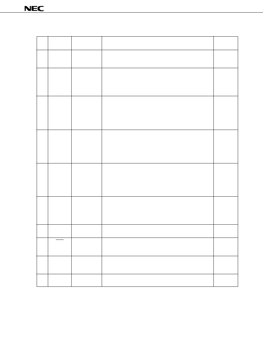
Clock output pin of electronic volume control
For details of data output, see Appendix.
Data input/output pin of electronic volume control
For details of data output, see Appendix.
Charge pump output pin of phase detector built into a PLL. If a
divided oscillator frequency is higher than the reference frequency,
the output of this pin goes high. If the divided oscillator frequency
is lower, the output goes low. If the divided oscillator frequency
agrees with the reference frequency, the output enters the floating
state.
Power-supply pin of the device
This pin supplies a voltage of 5 V
±
10 % while the device is
operating. The rise time (0 to 4.5 V) of V
DD
must not exceed 500
ms. If the rise time is significantly long or if the voltage falls below
the operating voltage but is between 0 V and 3.5 V, the state of an
initial setting diode switch may be read incorrectly.
Input pin of the local oscillator output (VCO) in the AM (MW, LW)
band
When tuned to broadcasts in the MW or LW band, this pin becomes
active. Otherwise, the pin is internally pulled down.
To protect the built-in AC amplifier, block the flow of direct current
with a capacitor, then input the frequency.
Input pin of the local oscillator output (VCO) in the FM band
When tuned to broadcasts in the FM band, this pin becomes active.
Otherwise, the pin is internally pulled down.
Because an AC amplifier is incorporated, block the flow of direct
current with a capacitor, then input the frequency.
Input pin of the device selection signal
Always pull up the pin.
Serial clock output pin for controlling the LCD controller/driver
(
µ
PD7225)
Serial data output pin for controlling the LCD controller/driver
(
µ
PD7225)
Input pin of the door switch
See Chapter 3 for details.
Pin
No.
Symbol
Pin name
Description
I/O type
1. PIN FUNCTIONS
µ
PD17012GF-058
8
12
13
14
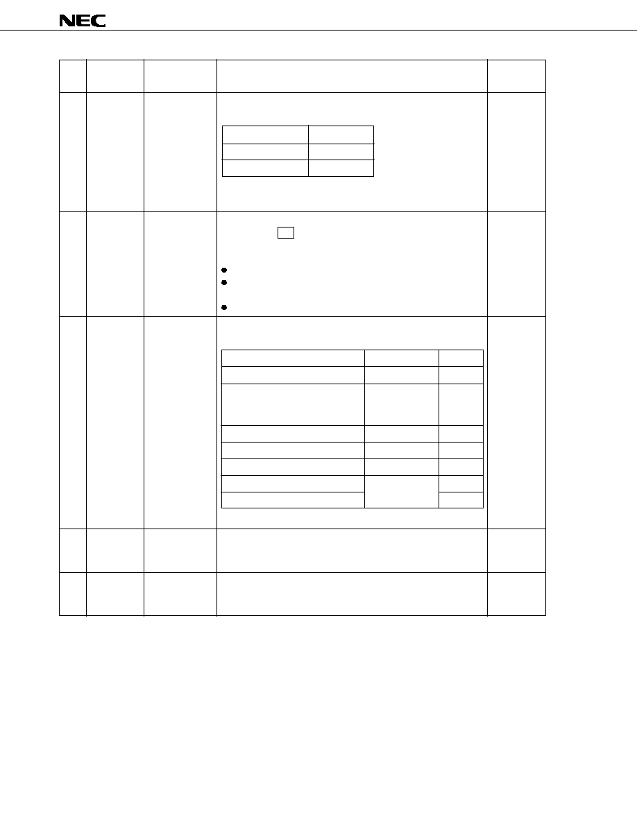
FMIFC
AMIFC
KY-IN
FM intermediate
frequency input
AM intermediate
frequency input
Key input
Input
Input
Input
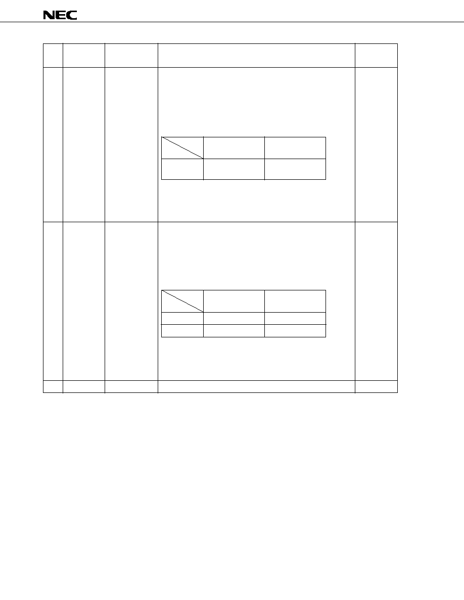
Pin
No.
Symbol
Pin name
Description
I/O type
Input pin of the intermediate frequency (IF) in the FM band
To protect the built-in AC amplifier, block the flow of direct current
with a capacitor, then input the frequency.
When the ENFMIF switch (initial setting diode) is set to 1, this pin is
used to detect a station during auto-tuning.
If the input frequency range and conditions listed below are
satisfied, it is judged that a station has been found.
A frequency within input frequency range <1> must be input within
20 ms of the PLL being locked. If a frequency is included in both
input frequency ranges <1> and <2>, it is judged that a station has
been found. Auto-tuning is stopped.
Input pin for the intermediate frequency (IF) in the AM (MW, LW)
band. To protect the built-in AC amplifier, block the flow of direct
current with a capacitor, then input the frequency.
If the initial setting diode ENAMIF is set to 1, this pin is used to
detect whether a station is found in auto-tuning.
If the input frequency range and conditions listed below are
satisfied, it is judged that a station has been found.
A frequency within input frequency range <1> must be input within
20 ms of the PLL being locked. If a frequency is included in both
input frequency ranges <1> and <2>, it is judged that a station has
been found. Auto-tuning is stopped.
Input pin for the key return signal of the momentary key matrix
10.7 MHz
±
50 kHz
FM
10.7 MHz
±
12.5 kHz
Input frequency
range <1>
Band
Input frequency
range <2>
Item
450
±
5
450
±
5
MW
LW
450
±
2
450
±
0.5
Input frequency
range <1> [kHz]
Band
Input frequency
range <2> [kHz]
Item

µ
PD17012GF-058
9
15
16
17
18
19
20
SD
DSP1
DSP2
BEEP
IGNITION
AGCC
Pin
No.
Symbol
Pin name
Description
I/O type
SD (station detector) signal input pin
If the following voltage is applied to this pin, it is judged that an SD
is found.
The SD signal is used to judge whether a station is found.
Output pin for the DSP chip control signal.
See the description of the DSP momentary key.
Beep sound output pin that functions when a momentary key is
pressed
If a momentary key is pressed, square waves (duty cycle 50 %) of
3 kHz are output for about 40 ms. This period agrees with the
period of the preceding mute.
A beep sound is output if a press of a momentary key causes the
LCD panel display or output port state to be changed, or if a hold
period of five seconds ends during scanning or preset memory
scanning.
The beep sound output is used as the alarm output when the alarm
function is used. If this output is not used, leave the pin open.
Pin to be connected to the car ignition switch.
Input a high level signal for normal operation of the device. Input a
low level signal when the device is not being used.
AGC (auto gain control) cut signal output pin in radio mode
The output goes high in auto-tuning, as shown below.
RDMUTE
15 ms 40 ms
300 - 400 ms
<1>
<2>
<3>
AGCC
Station found
Key-on
SD input
DSP control
output
Beep output
Ignition input
AGC cut output
2.227
0.977
1.211
0.977
LOCAL
DX
LOCAL
DX
When V
DD
is
set to 5 V
Voltage by which the presence of an
SD is assumed
Band
LOCAL/DX
mode
FM
MW
LW
28.5
◊
V
DD
or higher
64
12.5
◊
V
DD
or higher
64
15.5
◊
V
DD
or higher
64
12.5
◊
V
DD
or higher
64
Input
CMOS
push-pull
output
CMOS
push-pull
output
Input
CMOS
push-pull
output
<1> : Waiting for key-on chattering
<2> : Preceding mute
<3> : Following mute

µ
PD17012GF-058
10
21
22
23
24
25
26
58
27
28
|
30
31
LOC
AMUTE
RDMUTE
X
OUT
X
IN
GND
ALARMOUT
KEYS2
|
KEYS0
LOUD
Local signal
output
Audio mute
output
Radio mute
output
Crystal
Ground
Alarm-out
output
Key source
signal output
Loudness output
Local signal output pin in radio mode
The operation depends on the mode, as described below:
(1) In radio mode, radio-monitor tape mode, radio-monitor CD
mode
The LOC output goes high only in auto-tuning in the local state.
The level of the LOC output depends on both the tuning state
and LOCAL/DX state. The relationships are listed below:
(2) In other modes
The output goes low.
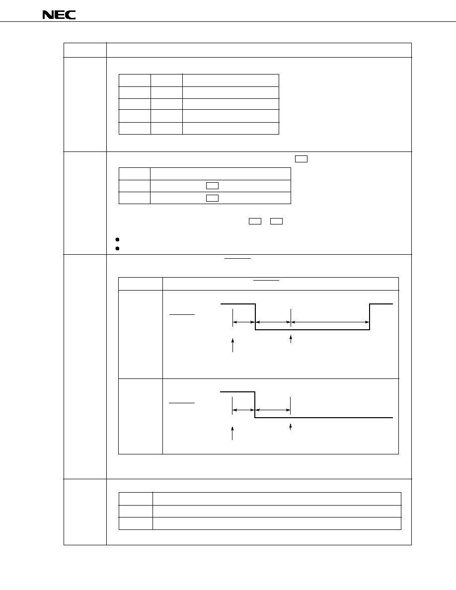
Output pin of the tape or CD mute signal
The operation depends on the mode, as described below:
(1) In radio mode, radio-monitor tape mode, radio-monitor CD
mode, power-off mode
The output goes low.
(2) In CD mode and tape mode
The output goes high.
See Chapter 7 for details.
Output pin of radio mute signal
The operation depends on the mode, as described below:
(1) In radio mode, radio-monitor tape mode, radio-monitor CD
mode; at radio-on, radio-off; at band switching; at switch-
ing of the frequency to be received
The output goes low.
(2) In CD mode and tape mode
The output method can be selected by setting the initial setting
diode MUTESEL. (See Section 2.6.1.) If the radio-monitor
function is used, set MUTESEL to 0 and bring the output low.
See Chapter 7 for details.
Pin for connecting a crystal
A 4.5-MHz crystal is connected.
Ground pin
Connect pins No. 26 and No. 58 to an identical potential.
Alarm-out output pin
See Chapter 3 for details.
Output pin for the key source signal for the momentary key matrix.
Output pin for the loudness control signal
When the loudness state is set, the output goes high.
Pin
No.
Symbol
Pin name
Description
I/O type
Auto-tuning state
LOCAL/DX state
LOC output level
LOCAL
High
In progress
DX
Low
Not performed
Don't care
Low
CMOS
push-pull
output
CMOS
push-pull
output
CMOS
push-pull
output
-
Input
-
CMOS
push-pull
output
N-ch open-
drain output
CMOS
push-pull
output

µ
PD17012GF-058
11
32
33
34
35
|
37
40
42
43
38
39
41
POWER
BAND1
BAND2
IC
POUT
ILLUMI
LCD CS
Power output
Band switching
signal output
IC
Detachable
panel state
signal
Illumination
signal output
LCD chip select
signal output
CMOS
push-pull
output
CMOS
push-pull
output
-
CMOS
push-pull
output
CMOS
push-pull
output
CMOS
push-pull
output
The output is inverted each time the POWER key is pressed.
Use this pin to turn the radio on or off.
Connecting this pin to transistor switch RDSET enables power-on
and off of the radio.
Output pin of the band switching signal in radio mode
The operation depends on the mode, as described below:
(1) In radio mode, radio-monitor tape mode, radio-monitor CD
mode
If the band to be received is switched by pressing the band
switching key, the output depends on the band, as listed below:
(0: Low, 1: High)
(2) In tape mode, CD mode, power-off mode
The output goes low.
Internally connected pin.
Leave the pins open.
Output pin of the detachable panel state signal
When the DTH switch is set to off, the pin outputs the detachable
panel state signal, having a frequency of 1 Hz and a duty cycle of
1/2.
Illumination signal output pin
The output methods are selected according to the states of the ILLA
and ILLB initial setting diodes, as follows:
(1: Shorted by the diode; 0: Open)
Output pin for the chip select signal
This pin is used as an output pin of the chip select signal for the
external LCD controller/driver (
µ
PD7225).
When the output goes low, the external LCD controller/driver is
enabled.
Pin
No.
Symbol
Pin name
Description
I/O type
Pin
BAND1
BAND2
Band
MW
0
0
LW
0
1
FM
1
0
Caution When the
µ
PD7225 external LCD controller/driver is used, connect the C/D pin to the V
DD
pin at
the
µ
PD7225.
ILLA
ILLB
Function
0
0
Loudness function only
0
1
Loudness/illumination functions
1
0
Loudness/illumination functions
1
1
Loudness function only
µ
PD17012GF-058
12
44
45
46
47
48
|
57
59
|
62
MTL
CDOUT
MODE2
MODE1
KS9
|
KS0
K3
|
K0
METAL signal
output
CD mode output
Mode signal
output
Key source
signal output
Key return signal
input
CMOS
push-pull
output
CMOS
push-pull
output
CMOS
push-pull
output
CMOS
push-pull
output
Input
METAL signal output pin
The output level depends on the METAL state, as listed below:
If the TPSET switch is set to on, the output level depends on the
METAL state, regardless of the current mode.
CD mode output pin
Each time the CD momentary key is pressed, the CDOUT output
is inverted. In the following modes, the CDOUT output is always
set low:
When IGNITION is low
In power-off mode (when IGNITION is high and the radio, tape,
and CD are off)
When the DTH transistor switch is set to off
Mode switching signal output pin
The output depends on the mode, as listed below:
Output pin of the key source signal of the key matrix
Input pin of the key return signal of the key matrix
Pin
No.
Symbol
Pin name
Description
I/O type
METAL state
Output level
ON
High
OFF
Low
Mode
MODE1
MODE2
When IGNITION is low
0
0
When IGNITION is high and the
0
0
radio, tape, and CD are off
(power-off mode)
In radio mode
1
0
In tape mode
0
0
In CD mode
0
1
In radio-monitor tape mode
1
0
In radio-monitor CD mode
1
(0: Low, 1: High)
µ
PD17012GF-058
13
63
64
MONO
REM
MONO signal
output
Remote-
controller signal
input
CMOS
push-pull
output
Input
MONO signal output pin
This pin functions as a MONO signal output pin in radio mode,
radio-monitor tape mode, or radio-monitor CD mode.
The output level depends on the selected band and the MONO
state, as listed below:
If the MW band is selected, the output level depends on the
setting of the initial setting diode MWS, as listed below:
(1: Shorted by the diode, 0: Open)
Input pin for the infrared remote-controller signal. The output of the
preamplifier (such as
µ
PC2800HA) of a remote controller is
connected. Use the
µ
PD6121G to send signals from the remote-
controller.
Pin
No.
Symbol
Pin name
Description
I/O type
Selected band
MONO state
Output level
FM
ON
High
OFF
Low
LW
Don't care
Low
MWS
MONO state
Output level
1
ON
High
OFF
Low
0
Don't care
Low

µ
PD17012GF-058
14
2. KEY MATRIX STRUCTURE
2.1 Placement of the Initial Setting Diode, Alternation, and Transistor Switch Matrixes
: Initial setting diode matrix
: Alternation or transistor switch
-
: Open
2.2 Switch Connection
Alternation switch
Transistor switch
Initial setting diode
KSm
Kn
KSm
Kn
V
DD
KSm
Kn
Input pin (pin
number)
K3 (59)
K2 (60)
K1 (61)
K0 (62)
Output pin
(pin number)
KS9 (48)
-
DISALARM
VOLATT_L
VOLATT_H
KS8 (49)
RDSET
ST
DTH
VKYSEL
KS7 (50)
FF
RL
CDSET
TPSET
KS6 (51)
IFAM
-
-
MWS
KS5 (52)
AUTO500
MUTESEL
AUTOLOC
FAD_SEL
KS4 (53)
CKHLT
ILLA
ILLB
KTAPE
KS3 (54)
NOCLK
CLKDISP
FLASH
DISAMEMO
KS2 (55)
ENFMIF
ENAMIF
PRIO2
PRIO1
KS1 (56)
ENFM
DISFM3
ENMW2
DISLW
KS0 (57)
-
AREA3
AREA2
AREA1

µ
PD17012GF-058
15
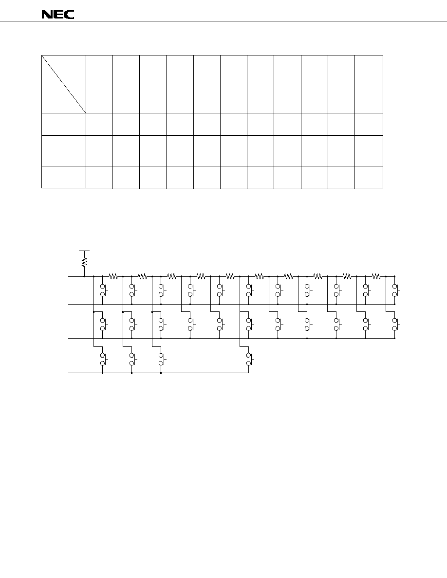
2.3 Initial Setting Diode, Alternation, and Transistor Switch Matrix Connection
52
KS5
53
KS4
54
KS3
55
KS2
56
KS1
57
KS0
58
59
K3
60
K2
61
K1
62
K0
50
49
48
KS7
51
KS6
KS8
KS9
PD17012GF-058
µ
: Alternation or transistor switch
: Initial setting diode
µ
PD17012GF-058
16
2.4 Momentary Key Matrix Placement
- : Open
2.5 Momentary Key Matrix Connection
KEYS0 (30)
KEYS1 (29)
KEYS2 (28)
M1
BAND
RDMONI
Input
voltage
Selection
pin
(pin number)
0 to 0.04
V
DD
0.05 to
0.12
V
DD
0.13 to
0.20
V
DD
0.21 to
0.29
V
DD
0.30 to
0.38
V
DD
0.39 to
0.48
V
DD
0.49 to
0.57
V
DD
0.58 to
0.66
V
DD
0.67 to
0.76
V
DD
0.77 to
0.84
V
DD
0.85 to
0.91
V
DD
M2
CD
SCAN
UP
M3
POWER
SCAN
DWN
M4
VOL
UP
-
M5
VOL
DWN
-
M6
VOL
SEL
MTL
SEEK
UP
LOUD/
ILLMI-
NATION
-
ALARM
MUTE
-
MAN
UP
DISP
-
MAN
DWN
DSP
-
MONO/
LOC
P.SCAN
-
V
DD
KY-IN
KEYS0
KEYS1
KEYS2

µ
PD17012GF-058
17
2.6 Description of the Key Matrixes
2.6.1 Initial setting diode matrixes
The
µ
PD17012GF-058 has the following 18 initial setting diode matrixes. When the V
DD
is supplied with power
for the first time (at a power-on reset), the states of the diodes in these matrixes are read in. In all other occasions,
they are ignored.
(1) Switches to specify the reception area
AREA1, AREA2, and AREA3
(2) Switches to specify the reception band
DISFM3, DISLW, ENFM, and ENMW2
(3) Switch to specify whether to use the auto-storage function
DISAMEMO
(4) Switches to specify whether to use the frequency counter for detecting broadcasting stations
ENAMIF and ENFMIF
(5) Switch to specify tuning operation
AUTO500
(6) Switches to specify display priority
PRIO1 and PRIO2
(7) Switches to specify the clock function
CLKDISP, FLASH, and NOCLK
(8) Switches to specify the tape function
KTAPE
(9) Switch to specify the mute output
MUTESEL
(10) Switch to specify the local operation
AUTOLOC
(11) Switch to specify the intermediate frequency for the AM (MW, LW) band
IFAM
(12) Switch to specify whether the MW band stereo reception function is available
MWS
(13) Switch to specify that the standby mode has no clock
CKHLT

µ
PD17012GF-058
18
(14) Switch to specify whether the electronic volume control fader function is available
FAD_SEL
(15) Switch to specify which key (VOL UP/VOL DWN or MAN UP/MAN DWN) is used for electronic volume
control
VKYSEL
(16) Switches to specify the gain of the electronic volume control
VOLATT_H and VOLATT_L
(17) Switches for setting illumination control
ILLA and ILLB
(18) Switch for specifying whether the alarm function is used
DISALARM
To set these switches to 1, short the diodes in each matrix. To set these switches to 0, keep the diodes open.
The functions of the initial setting diode matrixes are summarized below (in alphabetical order).

µ
PD17012GF-058
19
Initial setting
diode
Description
These switches are used to specify the reception area.
The following table lists the settings of the switches and the corresponding reception areas.
See the summary of functions for the reception frequencies in each reception area.
(1: Shorted by the diode; 0: Open)
This switch specifies the function of the MAN UP and MAN DWN keys. With the AUTO500 switch, it is
possible to use the MAN UP and MAN DWN keys also for auto-tuning (seek operation), as follows.
(1: Shorted by the diode; 0: Open)
AREA1
AREA2
AREA3
AUTO500
AREA3
AREA2
AREA1
Area
0
0
0
Western Europe
0
0
1
Australia
Middle and Near East
0
1
0
Japan
0
1
1
USA 1
1
0
0
USA 2
1
0
1
Eastern Europe
1
1
0
USA 3
1
1
1
China
0
1
Only manual tuning is performed.
Each time the key is pressed, the frequency counter is incremented or decremented by
one channel. Keeping the key pressed for at least 0.5 seconds triggers manual fast
increment/decrement.
Both manual and auto-tuning are performed.
Each time the key is pressed, the frequency counter is incremented or decremented by
one channel. Keeping the key pressed for at least 0.5 seconds causes auto-tuning
(seek operation) to begin at the next channel.
The SEEK UP key becomes ineffective.
AUTO500
MAN UP and MAN DWN key function
µ
PD17012GF-058
20
Description
This switch specifies the local function, as follows:
(1: Shorted by the diode; 0: Open)
When the DISALARM and NOCLK initial setting diodes = 1, and CE = low, the CKHLT switch specifies
which standby mode is to be used, STOP or HALT.
(1: Shorted by the diode; 0: Open)
This switch specifies the clock display system (12/24) as follows:
(1: Shorted by the diode; 0: Open)
This switch specifies whether the alarm function is used, as follows:
(1: Shorted by the diode; 0: Open)
AUTOLOC
CKHLT
CLKDISP
DISALARM
0
1
Either or DX mode is selected according to a key entry (no auto local function avail-
able).
Each time the MONO/LOC key is pressed, switching occurs between local and DX
modes.
The local output is high in the local mode during auto-tuning (seek, scan, or auto-store).
The auto local function is performed (if available).
The MONO/LOC key becomes ineffective.
Keeping the SEEK UP , SCAN UP , SCAN DWN or P.SCAN key for at least 2
seconds triggers auto-tuning, turns on the "LOC" display, and makes the local output
high. After one cycle of auto-tuning is completed, a search begins in DX mode (with the
"LOC" display off and local output at a low level).
In modes other than auto-tuning , the "LOC" display is off and the local output is low. If
a key for the same operation (for example, the SEEK UP key during seek operation) is
pressed in local mode during auto-tuning, a search begins in DX mode at the same
frequency used when auto-tuning began. If the key is pressed in DX mode, auto-tuning
stops, and the frequency that was selected when auto-tuning began is reselected.
The same operation as above occurs when the AUTO500 is set to 1 (by keeping the
MAN UP or MAN DWN key pressed for at least 0.5 seconds).
AUTOLOC
Local function
Initial setting
diode
CKHLT
0
1
CE = low
STOP mode
HALT mode
CLKDISP
0
1
Clock display system
12-hour system
24-hour system
DISALARM
0
1
Description
Used
Not used
AM12 : 00
AM11 : 59
PM11 : 59
PM12 : 00
0 : 00
23 : 59

µ
PD17012GF-058
21
Description
This switch is used to inhibit the auto-storage function, as follows:
(1: Shorted by the diode; 0: Open)
These switches are used to specify the reception band.
Each switch has the following functions.
DISFM3: When set to 1, disables the FM3 band.
ENMW2: When set to 1, enables the MW2 band.
DISLW: When set to 1, disables the LW band for Western Europe and Eastern Europe. This
DISLW:
switch is ineffective in the other areas.
ENFM: When set to 1, enables only the FM band.
The following table lists the settings of these switches and the corresponding reception bands in each area.
(1: Shorted by the diode; 0: Open; -: Don't care)
DISAMEMO
DISFM3
DISLW
ENFM
ENMW2
DISAMEMO
Description
The auto-storage function is enabled.
Keeping the P.SCAN key pressed for at least 2 seconds triggers the auto-storage
operation.
The auto-storage function is disabled.
The P.SCAN key can be used only for the preset scan function.
0
1
Initial setting
diode
Area
ENFM
DISFM3
ENMW2
DISLW
Reception band
1
0
-
-
FM1, FM2, FM3
1
1
-
-
FM1, FM2
0
0
0
0
FM1, FM2, FM3, MW1, LW
0
0
0
1
FM1, FM2, FM3, MW1
0
0
1
-
FM1, FM2, FM3, MW1, MW2
0
1
0
0
FM1, FM2, MW1, LW
0
1
0
1
FM1, FM2, MW1
0
1
1
-
FM1, FM2, MW1, MW2
The other areas
1
0
-
-
FM1, FM2, FM3
1
1
-
-
FM1, FM2
0
0
0
-
FM1, FM2, FM3, MW1
0
0
1
-
FM1, FM2, FM3, MW1, MW2
0
1
0
-
FM1, FM2, MW1
0
1
1
-
FM1, FM2, MW1, MW2
Western Europe
Eastern Europe

µ
PD17012GF-058
22
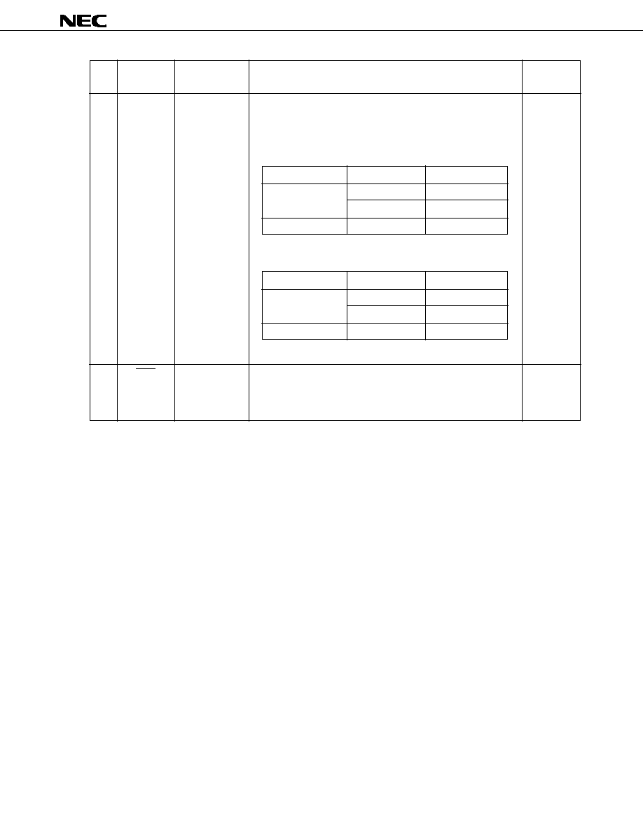
Description
These switches specify whether to use the frequency counter to detect a broadcasting station, as follows:
(1: Shorted by the diode; 0: Open)
This switch specifies whether to enable the electronic volume control fader function, as follows:
(1: Shorted by the diode; 0: Open)
This switch specifies how a colon (:) is used in the clock display, as follows:
(1: Shorted by the diode; 0: Open)
This switch specifies the intermediate frequency for the AM band (MW and LW), as follows:
(1: Shorted by the diode; 0: Open)
ENAMIF
ENFMIF
FAD_SEL
FLASH
IFAM
Band
Frequency counter and SD method
Frequency counter and SD method
Frequency counter and SD method
SD method
SD method
Frequency counter and SD method
SD method
SD method
1
1
0
0
1
0
1
0
FM
MW, LW
FM
MW, LW
FM
MW, LW
FM
MW, LW
ENFMIF
Method to detect a station
ENAMIF
FAD_SEL
0
1
Description
The fader function is enabled.
Pressing the VOL SEL key switches the electronic volume control mode as shown
below.
Balance
Volume
Bass
Treble
Fader
The fader function is disabled.
Pressing the VOL SEL key switches the electronic volume control mode as shown
below.
Volume
Bass
Balance
Treble
FLASH
0
1
Colon (:) display
Stays on.
Blinks.
Frequency: 1 Hz
Duty cycle: 6 on and 4 off
IFAM
0
1
Intermediate frequency
450 kHz
10.71 MHz
Initial setting
diode
µ
PD17012GF-058
23
Description
These switches set illumination control, as follows:
(1: Shorted by the diode; 0: Open)
This key specifies whether to assign the tape function (MTL) to the M5 radio function key, as follows:
(1: Shorted by the diode; 0: Open)
Regardless of the states of the KTAPE switch, the M1 to M6 keys are used to access a preset memory
and enable or disable writing to it.
Radio-monitor tape mode
Radio-monitor CD mode
This switch specifies how the state of the RDMUTE pin output is to change in tape and CD modes, as
follows:
(1: Shorted by the diode; 0: Open)
See Chapter 7 for details.
This switch specifies whether to enable the MW band stereo reception function, as follows:
(1: Shorted by the diode; 0: Open)
ILLA
ILLB
KTAPE
MUTESEL
MWS
Initial setting
diode
ILLA
ILLB
Function
0
0
Loudness function only
0
1
Loudness/illumination functions
1
0
Loudness/illumination functions
1
1
Loudness function only
KTAPE
Function
0
In tape mode, the M5 key is not used for MTL.
1
In tape mode, the M5 key is used for MTL.
MUTESEL
RDMUTE pin output
The mute function is disabled in tape and CD modes.
15 ms
40 ms
600 - 700 ms
Low level output at the MODE pin
The mode is switched by the TPSET and CDSET switches.
RDMUTE pin output
When MUTESEL = 1, do not use the radio monitor function.
The mute function remains turned on in tape and CD modes.
15 ms
40 ms
Low level output at the MODE pin
The mode is switched by the TPSET and CDSET switches.
RDMUTE pin output
1
0
MWS
1
0
Description
The MW band stereo reception function is enabled.
The MW band stereo reception function is disabled.
µ
PD17012GF-058
24
Description
This switch specifies whether a clock is available.
(1: Shorted by the diode; 0: Open)
These switches specify a privileged display. The term privileged display means the display which is
resumed in five seconds after any other display is selected, if no key is pressed.
The PRIO1 and PRIO2 switches can determine the privileged display only when the NOCLK initial setting
diode = 0 (with a clock). If NOCLK = 1 (without a clock), the states of these switches are ignored.
NOCLK
PRIO1
PRIO2
NOCLK
0
1
Clock
Available
Unavailable
Initial setting
diode
Privileged
display
PRIO1
PRIO2
Description
0
0
None
Display switching occurs when the DISP key or a preset number
key is pressed.
In radio mode
Each time the DISP key is pressed, switching occurs between
the frequency and clock displays.
Pressing a preset number key during clock display causes the
frequency display to appear.
In tape mode
Each time the DISP key is pressed, switching occurs between
the "
" and clock displays.
In CD mode
Each time the DISP key is pressed, switching occurs between
the "
" and clock displays.
In radio-monitor tape mode
Each time the DISP key is pressed, switching occurs among
the "
", frequency, and clock displays.
Pressing the preset number key during "
" or clock display
causes the frequency display to appear.
Radio-monitor tape mode begins with the frequency display.
In radio-monitor CD mode
Each time the DISP key is pressed, switching occurs among
the "
", frequency, and clock displays.
Pressing a preset number key during "
" or clock display
causes the frequency display to appear.
Radio-monitor CD mode begins with the frequency display.
(0: Open)

µ
PD17012GF-058
25
Description
PRIO1
PRIO2
Privileged
display
PRIO1
PRIO2
Description
1
0
Frequency
In 5 seconds after the DISP key is pressed to shift from the
frequency, "
", or "
" display to the clock display, the previous
display is resumed if no other key is pressed.
In radio mode
Usually the frequency display appears and remains. Pressing
the DISP key causes the clock display to appear for 5
seconds.
Pressing the DISP key or a preset number key within this 5-
second period of the clock display resumes the frequency
display.
In tape mode
Usually the "
" display appears and remains. Pressing the
DISP key causes the clock display to appear for 5 seconds.
Pressing the DISP key again within this 5-second period of
clock display resumes the "
" display.
In CD mode
Usually the "
" display appears and remains. Pressing the
DISP key causes the clock display to appear for 5 seconds.
Pressing the DISP key again within this 5-second period of
the clock display resumes the "
" display.
In radio-monitor tape mode
Usually the "
" display appears and remains. Pressing the
DISP key causes the frequency display to appear for 5
seconds.
Pressing the DISP key again within this 5-second period of
the frequency display causes the clock display to appear.
Pressing the DISP key again within this 5-second period of
the clock display causes the "
" display to appear.
Pressing a preset number key during "
" or clock display
causes the frequency display to appear for 5 seconds.
In radio-monitor CD mode
Usually the "
" display appears and remains. Pressing the
DISP key causes the frequency display to appear for 5
seconds.
Pressing the DISP key again within this 5-second period of
the frequency display causes the clock display to appear.
Pressing the DISP key again within this 5-second period of
the clock display causes the "
" display to appear.
Pressing a preset number key during "
" or clock display
causes the frequency display to appear for 5 seconds.
(1: Shorted by the diode; 0: Open)
Initial setting
diode
µ
PD17012GF-058
26
Description
PRIO1
PRIO2
Privileged
display
PRIO1
PRIO2
Description
0
1
1
1
Clock
-
The clock display has precedence over the other displays.
In radio mode
Usually the clock display appears and remains. Pressing the
DISP key causes the frequency display to appear for 5
seconds.
Pressing the DISP key again within this 5-second period of
frequency display resumes the clock display.
In tape mode
Usually the clock display appears and remains. Pressing the
DISP key causes the "
" display to appear for 5 seconds.
Pressing the DISP key again within this 5-second period of
"
" display resumes the clock display.
In CD mode
Usually the clock display appears and remains. Pressing the
DISP key causes the "
" display to appear for 5 seconds.
Pressing the DISP key again within this 5-second period of
the "
" display resumes the clock display.
In radio-monitor tape mode
Usually the clock display appears and remains. Pressing the
DISP key causes the "
" display to appear for 5 seconds.
Pressing the DISP key again within this 5-second period of
the "
" display causes the frequency display to appear.
Pressing the DISP key again within this 5-second period of
the frequency display causes the clock display to appear.
Pressing a preset number key during "
" or clock display
causes the frequency display to appear for 5 seconds.
In radio-monitor CD mode
Usually the clock display appears and remains. Pressing the
DISP key causes the "
" display to appear for 5 seconds.
Pressing the DISP key again within this 5-second period of
the "
" display causes the frequency display to appear.
Pressing the DISP key again within this 5-second period of
the frequency display causes the clock display to appear.
Pressing a preset number key during "
" or clock display
causes the frequency display to appear for 5 seconds.
Do not select this mode.
(1: Shorted by the diode; 0: Open)
If a clock is unavailable (NOCLK = 1), one of the displays listed below appears depending on what the
current mode is, regardless of the states of the PRIO1 and PRIO2 switches. The DISP key is ineffective.
Initial setting
diode
Mode
Display
Radio mode
Frequency
Tape mode
CD mode
Radio-monitor tape mode
Frequency
Radio-monitor CD mode
µ
PD17012GF-058
27
Description
VKYSEL
VOLATT_H
VOLATT_L
This switch specifies what keys are used for volume control in each electronic volume control mode, as
follows:
(1: Shorted by the diode; 0: Open)
These switches specify the gain of the electronic volume control, as follows:
VKYSEL
0
1
Description
The VOL UP and VOL DWN keys are used for volume control in each electronic
volume control mode.
The MAN UP and MAN DWN keys are used for volume control in each electronic
volume control mode. The VOL UP or VOL DWN key is unusable for volume control.
VOLATT_H
0
0
1
1
VOLATT_L
0
1
0
1
Gain
11.25 dB
7.5 dB
0 dB
3.75 dB
Initial setting
diode

µ
PD17012GF-058
28
2.6.2 Alternation or transistor switch
In the following table, a statement that a switch is on (off) means that a high (low) level is input.
Alternation/
transistor switch
Description
CDSET
DTH
FF
RDSET
RL
ST
TPSET
This switch selects CD mode. It is effective only when the CE pins is at a high level. Setting this switch to
on selects CD mode.
This is the input switch to specify whether the detachable panel is attached. When this switch is off, it
indicates that the panel is detached.
This is the fast forward signal input switch for tape mode.
FF
RL
0
1
0
1
0
1
The tape run direction indicator ( ) may light depending on the state of the RL switch as listed below.
Indicator
: Does not light
: Lights
: Blinks (at 2.5 Hz)
0 : Off 1 : On
This switch selects radio mode. It is effective only when the CE pin is at a high level. If both CDSET and
TPSET switches are off, setting the RDSET switch to on selects radio mode.
This is the forward run signal input switch for tape mode. The tape run direction indicator (
) is
controlled according to the state of the FF switch. See the description of the FF switch for the state of the
indicator.
This switch is a stereo signal input switch for radio mode. For the FM band in radio mode, setting this
switch to on turns on the "ST" display. If the stereo reception function is available for the MW band (initial
setting diode MWS = 1), setting the ST switch to on with the MW band selected turns on the "ST" display.
However, the display is turned off in the monaural state.
This switch selects tape mode. It is effective only when the CE pins is at a high level. If the CDSET
switch is off, setting the TPSET switch to on selects tape mode.

µ
PD17012GF-058
29
2.6.3 Momentary keys
The functions of the momentary keys are summarized below (in alphabetical order).
Momentary key
Description
ALARM
BAND
CD
This key can be used only for setting alarm mode.
This key is effective when the IGNITION pin is at the low level and DISALARM initial setting diode = 0.
See Chapter 3 for details.
The BAND key is used to switch the reception band.
This key is effective when the current mode is radio, radio-monitor tape, or radio-monitor CD mode.
When the key is pressed, the reception band is switched sequentially as follows.
FM1
FM2
FM3
MW1
MW2
LW
However, inhibited bands are skipped. They are specified by the AREA1, AREA2, and AREA3 initial setting
diodes (to specify reception areas) and the DISFM3, DISLW, ENFM, and ENMW2 initial setting diodes (to
specify reception bands).
The band display and last channel vary during band switching within the same type of band (FM1
FM2
FM3, MW1
MW2).
The BAND key becomes ineffective in tape and CD modes.
Each time the CD key is pressed, the output of the CDOUT pin (pin 45) is inverted.
Using the CDOUT output makes it possible to implement an application such as described below:
Turning on/off a transistor switch connected to the CDSET pin according to the CDOUT output can switch
on/off the CD mode according to the state of the CD key.
KS
7
K
1
V
DD
45
CDOUT

µ
PD17012GF-058
30
Momentary key
Description
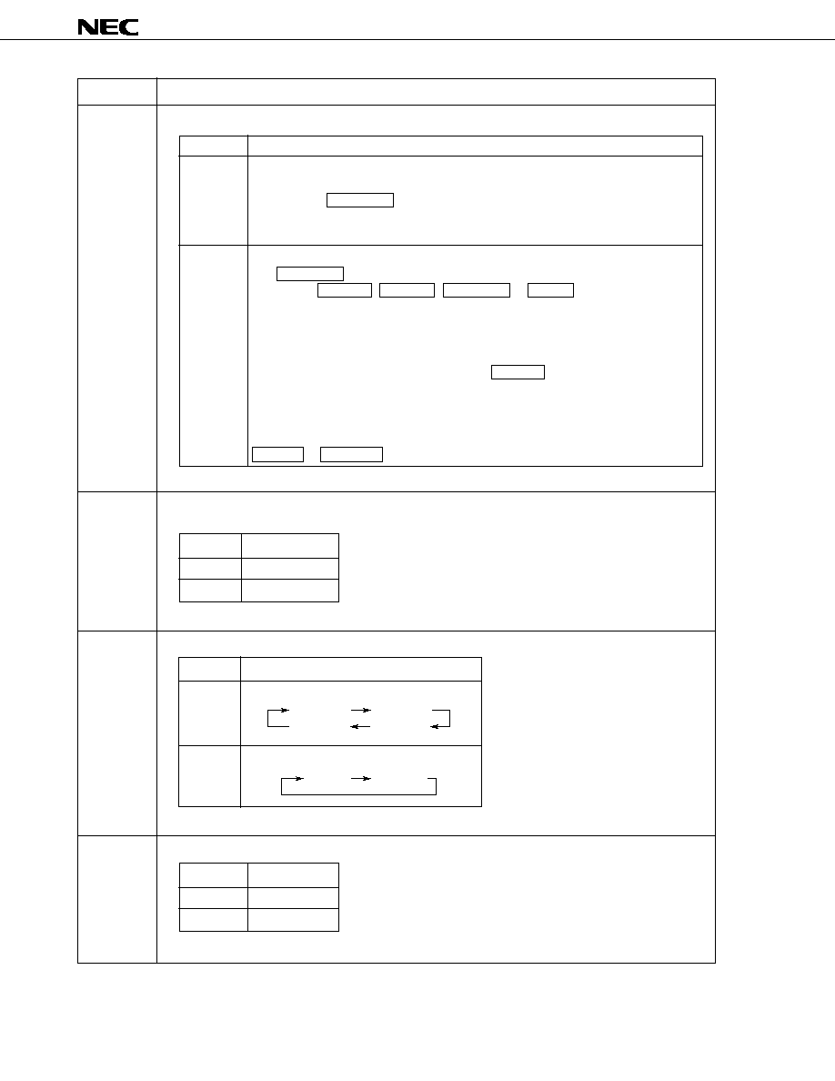
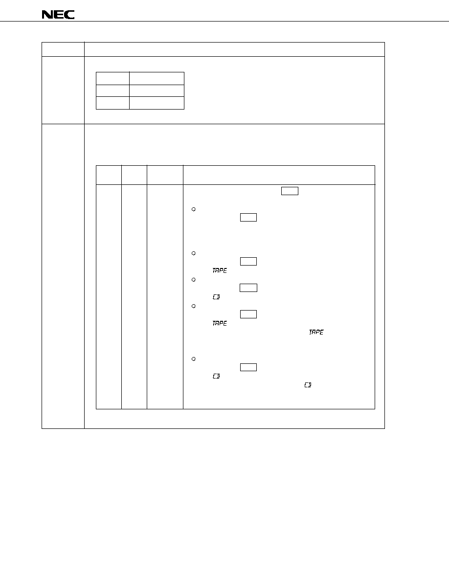
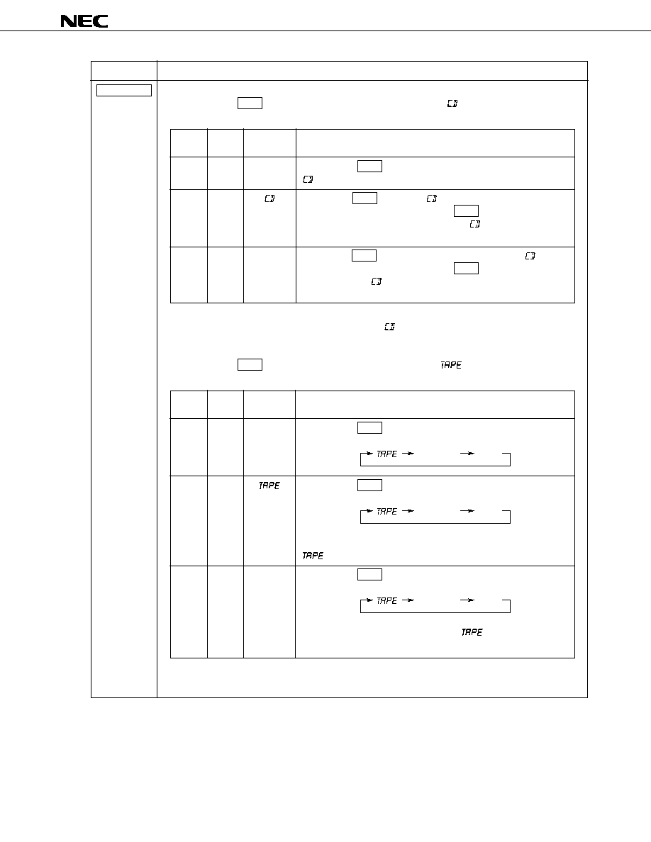
DISP
The DISP key is used to switch the display. It is effective when NOCLK initial setting diode = 0 (with a
clock).
Display switching occurs as follows:
(1) In radio mode
Each time the key is pressed, the display switches between the frequency and clock.
The DISP key is ineffective during seek-scanning and auto-preset scanning.
The operation depends on the states of the PRIO1 and PRIO2 initial setting diodes as follows:
(1: Shorted by the diode; 0: Open)
When radio mode is selected, the display begins with the frequency.
(2) In tape mode
Each time the DISP key is pressed, the display switches between "
" and the clock.
The operation depends on the states of the PRIO1 and PRIO2 initial setting diodes as follows:
(1: Shorted by the diode; 0: Open)
When radio mode is selected, the display begins with the "
" display.
Privileged
display
PRIO1
PRIO2
Description
0
1
0
0
0
1
None
Frequency
display
Clock
display
Each time the DISP key is pressed, the display switches between
the frequency and clock.
Pressing the DISP key during frequency display causes the clock
display to appear for 5 seconds. Pressing the DISP key during the
5-second period of clock display causes the frequency display to
appear again.
Pressing the DISP key during clock display causes the frequency
display to appear for 5 seconds. Pressing the DISP key during the
5-second period of frequency display causes the clock display to
appear again.
Privileged
display
PRIO1
PRIO2
Description
0
1
0
0
0
1
None
"
"
display
Clock
display
Each time the DISP key is pressed, the display switches between
the frequency and clock.
Pressing the DISP key during "
" display causes the clock
display to appear for 5 seconds. Pressing the DISP key during the
5-second period of clock display causes the "
" display to
appear again.
Pressing the DISP key during clock display causes the "
"
display to appear for 5 seconds. Pressing the DISP key during the
5-second period of "
" display causes the clock display to
appear again.
µ
PD17012GF-058
31
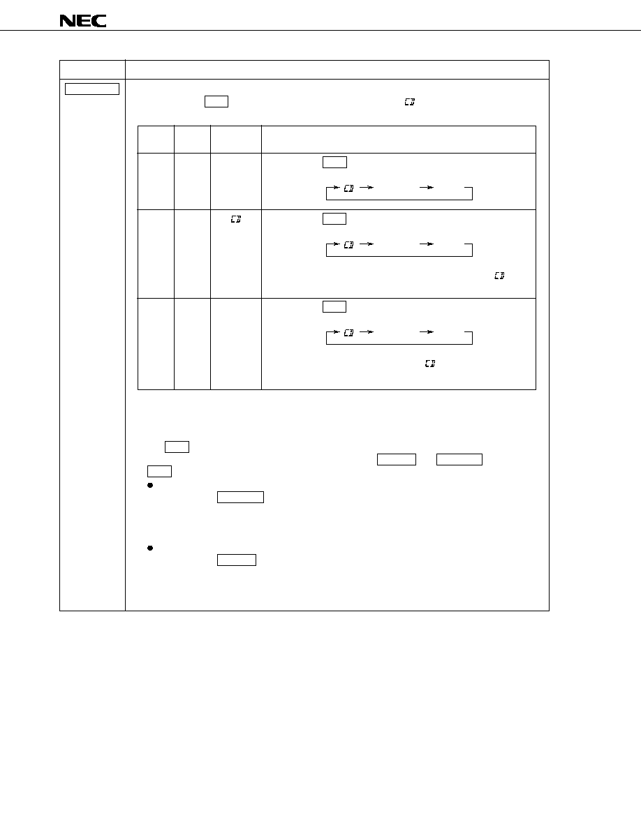
Momentary key
Description
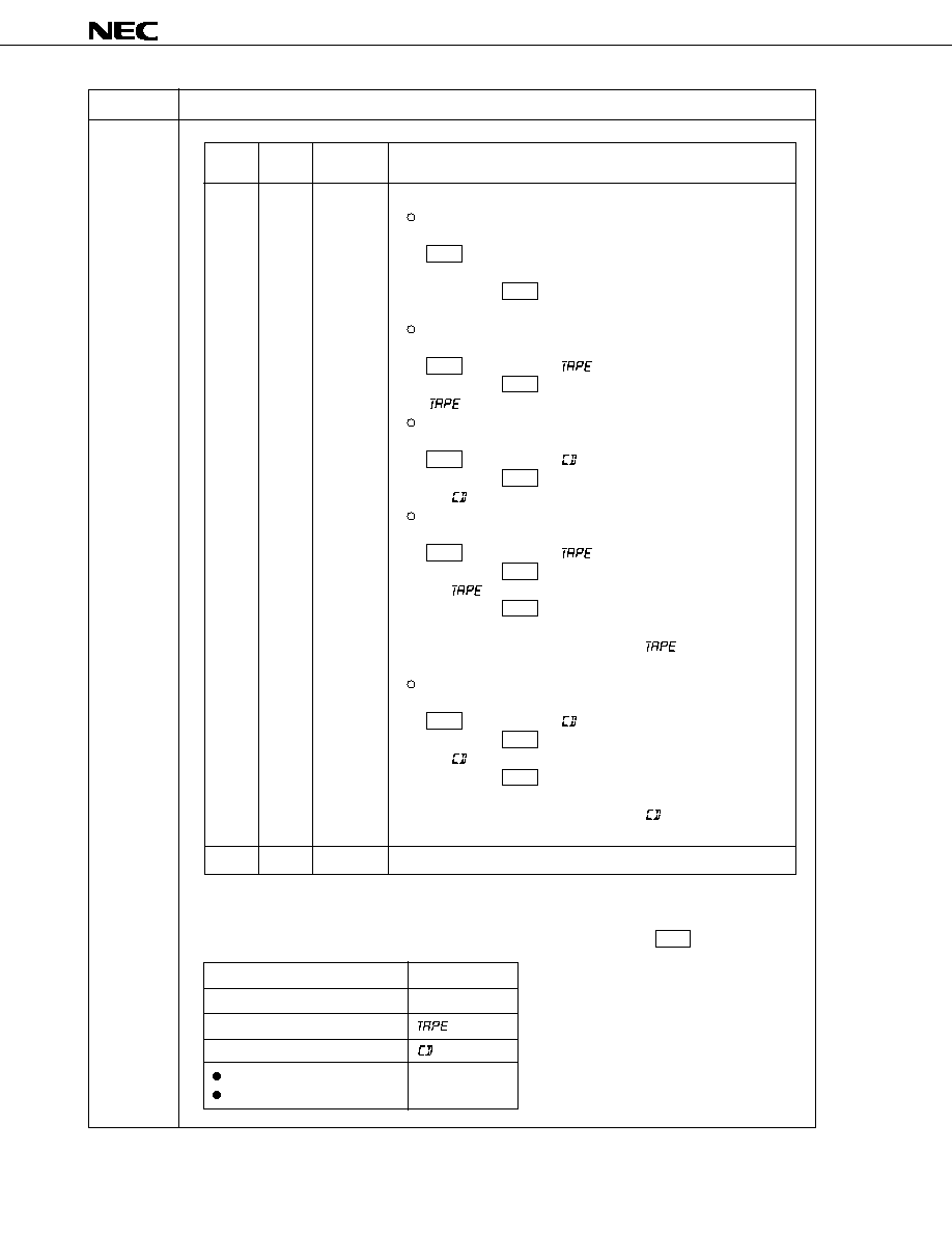
DISP
(3) In CD mode
Each time the DISP key is pressed, the display switches between "
" and the clock.
The operation depends on the states of the PRIO1 and PRIO2 initial setting diodes as follows:
(1: Shorted by the diode; 0: Open)
When CD mode is selected, the display begins with the "
".
(4) In radio-monitor tape mode
Each time the DISP key is pressed, the display switches among "
", frequency, and clock.
The operation depends on the states of the PRIO1 and PRIO2 initial setting diodes as follows:
(1: Shorted by the diode; 0: Open)
When radio-monitor tape mode is selected, the display begins with the frequency.
Privileged
display
PRIO1
PRIO2
Description
0
1
0
0
0
1
None
"
"
display
Clock
display
Each time the DISP key is pressed, the display switches between
"
" and clock.
Pressing the DISP key during "
" display causes the clock display
to appear for 5 seconds. Pressing the DISP key during the 5-
second period of clock display causes the "
" display to appear
again.
Pressing the DISP key during clock display causes the "
" display
to appear for 5 seconds. Pressing the DISP key during the 5-
second period of "
" display causes the clock display to appear
again.
Privileged
display
PRIO1
PRIO2
Description
0
1
0
0
0
1
None
"
"
display
Clock
display
Each time the DISP key is pressed, the display is toggled as
follows:
frequency
clock
" "
Each time the DISP key is pressed, the display is toggled as
follows:
frequency
clock
" "
If no key is pressed during frequency or clock display, the
"
" display appears again after 5 seconds.
Each time the DISP key is pressed, the display is toggled as
follows:
frequency
clock
" "
If no key is pressed during frequency or "
" display, the clock
display appears again after 5 seconds.
µ
PD17012GF-058
32
Momentary key
Description
DISP
(5) In radio-monitor CD mode
Each time the DISP key is pressed, the display switches among "
", frequency, and clock.
The operation depends on the states of the PRIO1 and PRIO2 initial setting diodes as follows:
(1: Shorted by the diode; 0: Open)
When radio-monitor CD mode is selected, the display begins with the frequency.
(6) During clock display
The DISP key is used to adjust the clock.
The minute and hour displays are adjusted by pressing the MAN UP and MAN DWN keys with the
DISP key held pressed, as follows:
Hour adjustment
Each time the MAN DWN key is pressed, the hour display is incremented by one. Keeping the
key pressed for at least 0.5 seconds increments the hour display at a rate of four per second (one
per 250 ms). The continuous increment continues until the key is released. The minute display,
second count, or pointer movement is not affected.
Minute adjustment
Each time the MAN UP key is pressed, the minute display is incremented by one. Keeping the
key pressed for at least 0.5 seconds increments the minute display at a rate of eight per second
(one per 125 ms). The continuous increment continues until the key is released. No carry-over
occurs to the hour display. The second count is reset to 0 at each adjustment.
Privileged
display
PRIO1
PRIO2
Description
0
1
0
0
0
1
None
"
"
display
Clock
display
Each time the DISP key is pressed, the display is toggled as
follows:
frequency
clock
" "
Each time the DISP key is pressed, the display is toggled as
follows:
frequency
clock
" "
If no key is pressed during frequency or clock display, the "
"
display appears again after 5 seconds.
Each time the DISP key is pressed, the display is toggled as
follows:
frequency
clock
" "
If no key is pressed during frequency or "
" display, the clock
display appears again after 5 seconds.
µ
PD17012GF-058
33
Momentary key
Description
DSP
LOUD/
ILLUMI-
NATION
Pressing the DSP key switches the output of the DSP1 and DSP2 pins, as follows. The initial value is
NORMAL. While the power is off, the output mode is NORMAL.
(1: Shorted by the diode; 1: Open)
In radio, tape, and CD modes, the output mode which was used last is recorded in memory for each mode.
Example
In radio, tape, or CD mode, "NORMAL," "CLASSIC," "ROCK," or "POP" is displayed, according to the
output mode.
Key for switching LOUD (loudness) control and illumination control.
(1) Loudness control
It is effective in radio, tape, and CD modes.
Each time the LOUD/ILLUMINATION key is pressed, the control of loudness and the electronic
volume control loudness function are switched on or off.
The following table lists the states of loudness, "LOUD" display, the LOUD pin output, and the elec-
tronic volume control IC.
Switching radio, tape, or CD mode does not affect the state of loudness.
Note In loudness ON mode, set the gain of the electronic volume to +7.5 dB.
In loudness OFF mode, set the gain of the electronic volume to 0 dB.
(2) Illumination control
Illumination control is effective in radio, tape, and CD modes.
When this key is pressed and held down for two seconds or more, the previous ILLUMI output is
inverted. The initial value is low-level output. The illumination control, however, can be enabled or
disabled by using the ILLA and ILLB initial setting diodes (see Section 2.6.1).
DSP1
DSP2
Output mode
0
0
NORMAL
0
1
CLASSIC
1
0
ROCK
1
1
POP
ON
OFF
Lights
Does not light
High level
Low level
Electronic volume
control IC state
Loudness ON mode
Note
Loudness OFF mode
Note
Loudness state
"LOUD" display
LOUD pin
Radio mode
Tape mode
Radio mode
(CLASSIC)
(ROCK)
(CLASSIC)
Last state

µ
PD17012GF-058
34
Momentary key
Description
M1
M2
M3
M4
M5
M6
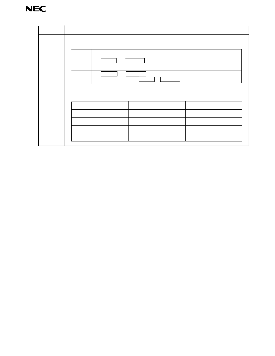
In radio mode, these keys are used to access a preset memory and control whether to enable writing to it.
In tape mode, the M5 keys are used for a tape function (MTL) key depending on the settings of the
KTAPE initial setting diode.
(1) In radio, radio-monitor tape, and radio-monitor CD modes
The M1 to M6 keys are used to access a preset memory and control whether to enable writing to it.
Each key can be set to the FM1, FM2, FM3, MW1, MW2 and LW bands (up to six bands) separately.
The functions of these keys are as follows:
Description
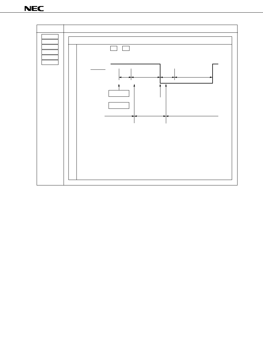
Keeping one of the M1 to M6 keys pressed for at least 2 seconds writes a frequency to the
preset memory corresponding to the pressed key.
When writing to the preset memory is completed, the radio mute signal is output as acknowl-
edgment.
Example
M1
M6
Key
operation
RDMUTE
pin output
15 ms
2 sec
40 ms
Beep
300 - 400 ms
keys are on
Display
Frequency or
clock display
The preset memory number corresponding to the
pressed key is displayed.
The frequency previously received is displayed.
to
When the frequency recorded in the currently selected preset memory is being received,
pressing the key corresponding to this preset memory does not trigger any operation except
during clock display. During clock display, pressing the key not only generates a beep but also
switches to the frequency display. Pressing the key, however, does not generate the radio
mute signal.
During the seek operation, pressing the key immediately accesses the preset memory (without
waiting 2 seconds).
Writing
µ
PD17012GF-058
35
Momentary key
Description
M1
M2
M3
M4
M5
M6
Description
Pressing one of the M1 to M6 keys and releasing it within 2 seconds calls the content of the
corresponding preset memory when the key is released.
Example
M1
M6
Key
operation
RDMUTE
pin output
15 ms
2 sec
40 ms
Beep
400 - 500 ms
keys are on
Display
Keys are off
Frequency or
clock display
The preset memory
number correspond-
ing to the pressed
key is displayed.
The frequency pre-
viously received
is displayed.
The preset memory number
corresponding to the pressed
key is displayed.
The frequency recorded in the
preset memory is displayed.
to
When the frequency recorded in the currently selected preset memory is being received,
pressing the key corresponding to this preset memory does not trigger any operation except
during clock display. During clock display, pressing the key not only generates a beep but also
switches to the frequency display. Pressing the key, however, does not generate the radio
mute signal.
During the seek operation, pressing the key immediately accesses the preset memory.
Calling

µ
PD17012GF-058
36
Momentary key
Description
M1
M2
M3
M4
M5
M6
When power is applied, the frequencies listed below are written to the M1 to M6 preset memories for
convenience of set adjustment.
Area
Eastern Europe
Western Europe
USA 1, USA 2, and
USA 3
Australia
Middle and Near East
Japan
China
65.0
87.5
522
522
144
87.5
522
522
144
87.5
530
87.5
531
76.0
522
87.0
531
67.0
87.7
603
621
155
87.7
603
621
155
87.9
620
87.9
612
76.4
603
87.7
540
70.5
96.3
1 386
1 530
256
96.3
1 386
1 530
256
105.1
1 490
105.1
1 395
76.0
1 386
87.0
531
72.5
105.9
522
522
144
105.9
522
522
144
87.5
530
87.5
531
76.0
522
87.0
531
74.0
87.5
522
522
144
87.5
522
522
144
87.5
530
87.5
531
76.0
522
87.0
531
68.5
92.3
954
1 098
208
92.3
954
1 098
208
97.1
1 010
97.1
963
85.6
954
92.3
585
FM1(MHz)
FM2(MHz)
MW1(kHz)
MW2(kHz)
LW(kHz)
FM1(MHz)
MW1(kHz)
MW2(kHz)
LW(kHz)
FM1(MHz)
MW1(kHz)
FM1(MHz)
MW1(kHz)
FM1(MHz)
MW1(kHz)
FM1(MHz)
MW1(kHz)
Memory
Band
M1
M2
M3
M4
M5
M6
The lowest frequency for each area is written to the M1 to M6 preset memories for the MW2 band for the
areas other than Europe 1 or Europe 2 and for the FM2 and FM3 bands.
Operation in tape mode
The M5 key may also be used as the tape function (MTL) key depending on the states of the KTAPE
initial setting diode. See Section 2.6.1 for details. See also the descriptions of the MTL key.
µ
PD17012GF-058
37
Momentary key
Description
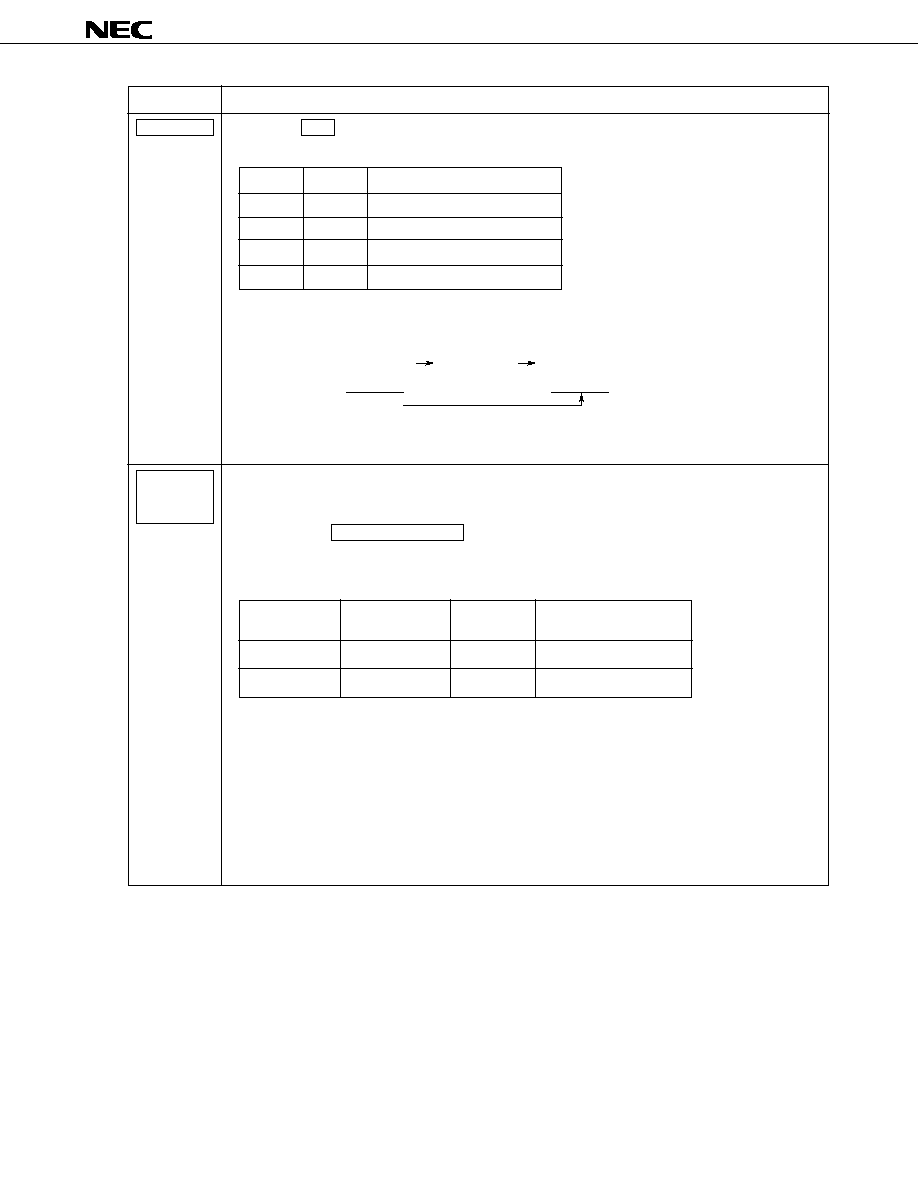
MAN UP
MAN DWN
The MAN UP and MAN DWN keys are used to increment and decrement the reception frequency in
radio mode, respectively. During clock display, they are also used in connection with the DISP key to
adjust the clock. They are again used to increase/decrease the volume of sound during electronic volume
control if VKYSEL = 1.
(1) In radio, radio-monitor tape, and radio-monitor CD modes
Either of the following operations occurs depending on the state of the AUTO500 initial setting diode.
(1: Shorted by the diode; 0: Open)
(2) While "
" is displayed in tape mode or "
" is displayed in CD mode
The MAN UP and MAN DWN keys are ineffective.
(3) During clock display
While the DISP key is held pressed during clock display, pressing the MAN UP and MAN DWN
keys enables adjusting the minute and hour displays, respectively. See the description of the DISP
key for how to adjust the minute and hour displays.
(4) When the electronic volume control function is effective and VKYSEL = 1:
The MAN UP and MAN DWN keys are used to adjust (increase and decrease) the volume of sound
in the electronic volume control mode selected using the VOL SEL key.
Once an electronic volume control mode is selected using the VOL SEL key, the MAN UP and
MAN DWN keys function in the same way as the VOL UP and VOL DWN keys.
In a mode other than an electronic volume control mode, the MAN UP or MAN DWN key does not
function as a volume control.
Pressing the MAN UP key works for each electronic volume control mode as follows:
0
1
Each time the MAN UP or MAN DWN key is pressed, the frequency counter is
incremented ( MAN UP key) or decremented ( MAN DWN key) by one step (one
channel space).
Keeping the key pressed for at least 0.5 seconds speeds the increment/decrement to a
rate of one step per 50 ms.
Each time the MAN UP or MAN DWN key is pressed, the frequency counter is
incremented ( MAN UP key) or decremented ( MAN DWN key) by one step (one
channel space).
Keeping the MAN UP key pressed for at least 0.5 seconds triggers a seek operation in
seek-up mode. This seek operation is the same as that triggered by the SEEK UP
key.
AUTO500
Description
Volume
Bass
Treble
Balance
Fader
Increases the main sound volume.
Increases the bass.
Increases the treble.
Emphasizes the sound volume from the right-side speaker.
Emphasizes the sound volume from the front speaker.
Mode
Function
µ
PD17012GF-058
38
Momentary key
Description
MAN UP
MAN DWN
MONO/LOC
MTL
Pressing the MAN DWN key works for each electronic volume control mode as follows:
The MONO/LOC key controls MONO (monaural)/STEREO mode and local (local/DX) mode.
(1) Monaural mode control
When this key is pressed and held down for two seconds or more, MONO and STEREO modes can be
switched.
The key is effective, when the current mode is radio, radio-monitor CD, or radio-monitor tape mode and
the FM or MW band is selected. (For the MW band, the key is effective if the MWS initial setting diode
= 1 and the tuner has a stereo capability.)
Each time the key is pressed, switching occurs between MONO and STEREO modes.
The following table lists MONO/STEREO mode and the states of the "ST" display and "MONO" display.
(2) Local mode control
The key is effective when the current mode is radio, radio-monitor CD, or radio-monitor tape mode and
when AUTOLOC initial setting diode = 0.
Each time the key is pressed, switching occurs between local and DX modes (only when the key is
released within two seconds).
The following table lists local/DX mode, the state of the "LOC" display, and LOC pin output.
Note A high level is output only during auto-tuning. The LOC pin is always at a low level during a tuning
type other than auto-tuning.
See the description of the LOC in Chapter 1.
The MTL key controls MTL (METAL) mode. It is effective when the current mode is radio or radio-
monitor tape mode. Each time the key is pressed, METAL mode is switched on or off.
The following table lists METAL mode on/off, the states of the "METAL" display, and METAL pin
output.
Volume
Bass
Treble
Balance
Fader
Decreases the main sound volume.
Decreases the bass.
Decreases the treble.
Emphasizes the sound volume from the left-side speaker.
Emphasizes the sound volume from the rear speaker.
Mode
Function
LOCAL
DX
Lights
Does not light
High level
Note
Low level
Local/DX mode
"LOC" display
LOC pin
MONO
STEREO
Does not light
Lights
Lights
Does not light
MONO/
STEREO mode
"ST" display
"MONO" display
ON
OFF
Lights
Does not light
High level
Low level
METAL mode
"METAL" display
METAL pin
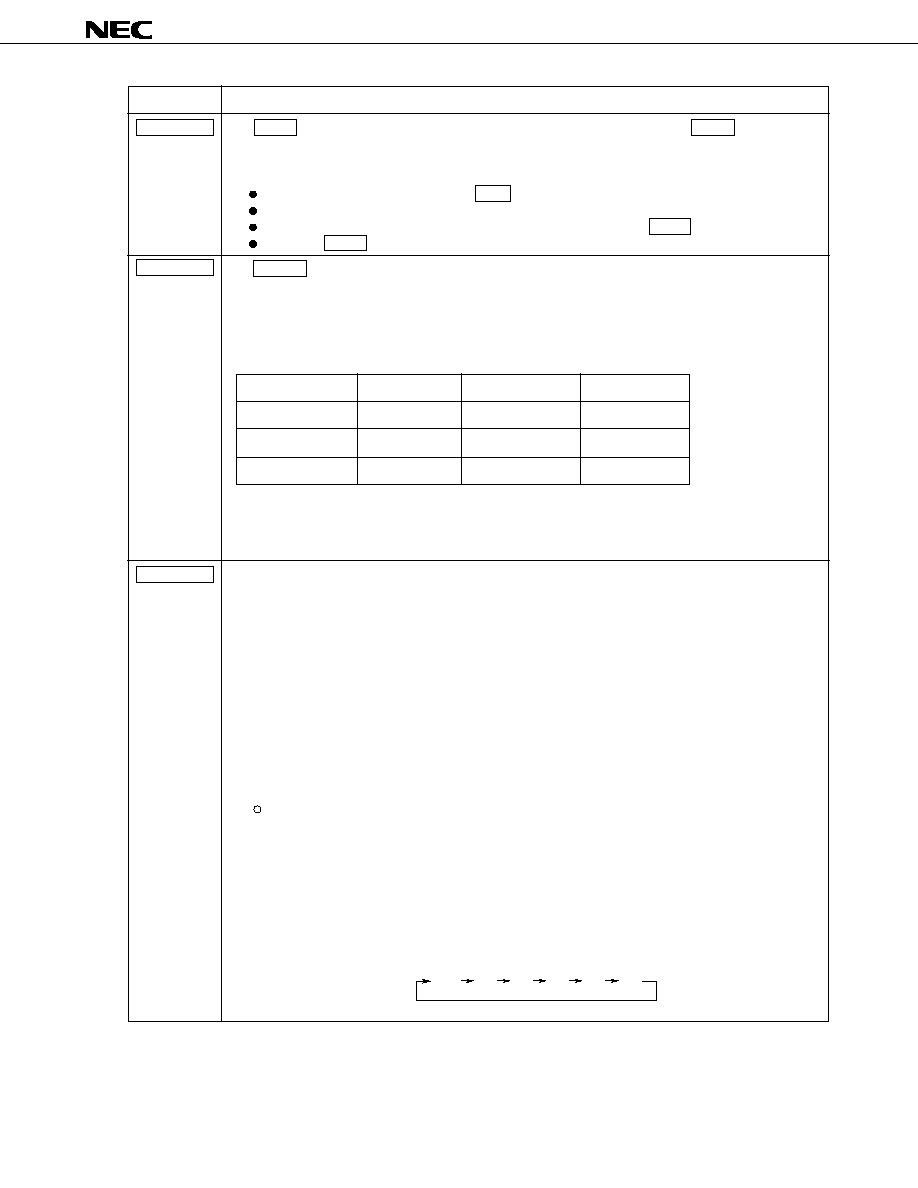
µ
PD17012GF-058
39
Momentary key
Description
MUTE
POWER
P.SCAN
The MUTE key controls the electronic volume control mute function. Pressing the MUTE key in a mode
other than mute mode selects mute (silent) mode. In mute mode, the volume value is displayed, and the
display is caused to blink.
The mute function is reset under the following conditions.
When an effective key other than the DISP key is pressed
When the mode is changed
When a station is detected during a seek or scan operation, with the MUTE pressed.
When the MUTE key is pressed during muting
The POWER key is used to control the power-on/off of the radio in momentary key mode. It is effective
when the IGNITION pin is at a high level. Pressing this key inverts the output of the POWER pin.
When the POWER pin output is set to low (the power is turned off), the tape recorder, CD player and radio
are forced to be turned off even when they have been in the power-on state. In this case, they are turned
off with or without clock display, according to whether they were in clock mode or non-clock mode.
The power-on mode varies as follows according to the state of the RDSET, TPSET, and CDSET switches.
This key functions as a preset scan and auto-storage key. The operation triggered by the key varies
depending on the state of the DISAMEMO initial setting diode.
(1) When DISAMEMO = 0 (with the auto-storage function):
The operation varies depending on the timing at which the key is operated.
(a) If the key is released within 2 seconds:
The preset scan operation begins immediately when the key is released.
(b) If the key is pressed for at least 2 seconds:
The auto-storage operation begins when 2 seconds elapse.
(2) When DISAMEMO = 1 (without the auto-storage function):
The preset scan operation begins immediately when the key is pressed.
The preset scan and auto-storage functions are described below.
Preset scan operation
The contents of each preset memory are called for 5 seconds each time automatically.
If a frequency other than those in the preset memories is being received, calling begins at M1. If
a frequency recorded in a preset memory is being received, calling begins at the preset memory
numbered one higher than that preset memory (for example, at the M4 preset memory if a
frequency recorded in the M3 preset memory is being received). This operation is illustrated
below.
Example If the FM1 band is being received:
M1
M2
M3
M4
M5
M6
FM1
REDSET
ON
ON/OFF
ON/OFF
TPSET
OFF
ON
ON/OFF
CDSET
OFF
OFF
ON
Mode
Radio mode
Tape mode
CD mode
Caution
At the initial power-on, the POWER pin outputs the high level. When the level of IGNITION
pin changes from low to high, the POWER pin outputs the level which have been set
before IGNITION becomes low, until the primary power supply is turned off.
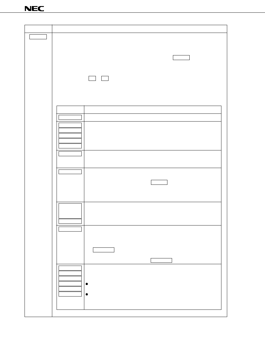
µ
PD17012GF-058
40
Momentary key
Description
P.SCAN
The same operation occurs for the MW (MW1 and MW2) and LW bands.
When the next preset memory is accessed after a 5-second hold period, a beep is generated. During each
5-second period, the preset memory number display blinks at 1 Hz (with a duty cycle of 50%). The "CH"
display does not blink.
To stop preset memory scanning during a 5-second hold period, press the P. SCAN key again or a preset
memory key that corresponds to the preset memory being currently accessed. It is possible to write to a
preset memory when another preset memory is on hold (for example, write to the M5 when the M1 is on
hold). When a write operation is completed, the preset scan operation ends.
Hold down one of the M1 to M6 keys for at least 2 seconds during the preset scan operation. The
frequency currently being received is written into the preset memory corresponding to the pressed key.
The preset scan operation ends immediately when any of these keys is pressed.
During the preset scan, each key functions as follows:
Key
Description
The scan operation stops, and the current frequency is received.
The scan operation stops, the operation corresponding to the pressed key begins
at the frequency being currently received.
In radio, radio-monitor tape, and radio-monitor CD modes, the scan operation
stops, and the operation corresponding to the pressed key begins at the frequency
being currently received.
Either of the following operations occurs depending on what the current mode is.
(1) In radio mode
The scan operation continues. The RDMONI key becomes ineffective.
(2) In radio-monitor tape and radio-monitor CD modes
The scan operation stops, and the operation corresponding to the pressed key
begins at the frequency being currently received.
The scan operation continues. The operation corresponding to the pressed key
begins.
Either of the following operations occurs depending on the state of the AUTOLOC
initial setting diode.
(1) When AUTOLOC = 0:
The scan operation continues. The operation corresponding to the
MONO/LOC key begins.
(2) When AUTOLOC = 1:
The scan operation continues. The MONO/LOC key becomes ineffective.
In radio, radio-monitor tape, and radio-monitor CD modes, the scan operation
stops. The other operations vary depending on the timing at which the key is
released.
If the key is released within 2 seconds:
The preset memory corresponding to the pressed key is accessed.
If the key is kept pressed for at least 2 seconds:
A frequency being currently received is written to the preset memory correspond-
ing to the pressed key.
P.SCAN
SCAN UP
SCAN DWN
SEEK UP
MAN UP
MAN DWN
BAND
RDMONI
LOUD/
ILLUMI-
NATION
POWER
MONO/LOC
M1
M2
M3
M4
M5
M6
µ
PD17012GF-058
41
Momentary key
Description
P.SCAN
Auto-storage function
Broadcasting stations are searched for automatically. The frequency of a detected station is written
to a preset memory. A method used to detect a station is determined according to the states of the
ENAMIF and ENFMIF initial setting diodes. A broadcasting station search begins at the frequency
being currently received and is performed through the frequencies in the ascending order.
When a station is detected, its frequency is written to a preset memory.
For the voltage with SD, see the description of the SD in Chapter 1.
The auto-storage operation varies depending on the state of the AUTOLOC initial setting diode as
follows:
(1) When AUTOLOC = 0 (with no auto local function):
The auto-storage function varies depending on which mode has been selected, local or DX, when the
function begins.
(a) If DX mode has been selected when the auto-storage function starts:
A search beings at the frequency being currently received and continues in the ascending order of
the frequency. When all frequencies are searched through, the search operation ends. If the
P. SCAN key is pressed during the search operation, the auto-storage operation ends, and the
frequency selected when the auto-storage operation began is received.
When all frequencies are searched through, if at least one station is detected, the contents of the
preset memories are updated, and the preset scan begins at the M1 preset memory.
How the contents of the preset memories are updated varies depending on the number of stations
detected.
If six or more stations are detected:
If six or more stations are detected, six stations with a higher SD input are selected and
written to the preset memories. A lower frequency is written to a lower-numbered preset
memory.
If less than six stations are detected:
If less than six stations are detected, lower frequencies are written to lower-numbered preset
memories. The contents of a preset memory will not be changed if there is no frequency
corresponding to it.
(b) If local mode has been selected when the auto-storage function starts:
A search begins in local mode at the frequency being currently received and continues in the
ascending order of the frequency. When all frequencies are searched through, if six or more
stations are not detected, the search switches to DX mode and continues in it. If six or more
stations are detected in local mode, or all frequencies are searched through in DX mode, the
auto-storage operation ends.
Pressing the P. SCAN key during the search operation stops the auto-storage operation, and
causes the frequency selected when the auto-storage memory began to be received.
If six or more stations are detected in local mode, or all frequencies are searched through in DX
mode, the auto-storage operation ends. If at least one station is detected, the contents of the
preset memories are updated, and the preset scan begins with the M1 preset memory.
How the contents of the preset memories are updated varies depending on the number of stations
detected, as follows:
If six or more stations are detected in local mode:
If six or more stations are detected, six stations with a higher SD input are selected and
written to the preset memories. A lower frequency is written to a lower-numbered preset
memory
If less than six stations are detected in local mode and some are detected in DX mode,
resulting in a total of six or more stations being detected:
Stations detected in DX mode with higher SD input levels are selected and added to the
number of stations detected in local mode so that the total becomes six. In this case, the
stations detected in local mode are excluded from those detected in DX mode.
The frequencies of the six stations are written to the preset memories, with a lower frequency
written to a lower-numbered preset memory.

µ
PD17012GF-058
42
Momentary key
Description
P.SCAN
If less than six stations are detected in local mode and some are detected in DX mode,
resulting in a total of less than six stations being detected:
If the same station is detected in DX and local modes, the station detected in DX mode is
deleted so that the same frequency will not be written to two preset memories. The frequen-
cies of the less than six stations detected are written to the preset memories, with a lower
frequency written to a lower-numbered preset memory. The contents of a preset memory will
not be changed if there is no frequency corresponding to it.
(2) When AUTOLOC = 1 (with the local function):
A search begins in local mode at the frequency being currently received and continues in the ascend-
ing order of the frequency. When all frequencies are searched through, if six or more stations are not
detected, the search switches to DX mode and continues in it. If six or more stations are detected in
local mode, or all frequencies are searched through in DX mode, the auto-storage operations ends.
Pressing the P. SCAN key in local mode switches to DX mode, and restarts the search operation at
the frequency selected when the previous search began. Any stations detected in local mode are
made ineffective. (Stations detected in local mode are excluded during preset memory updating.)
Pressing the P. SCAN key in DX mode ends the auto-storage operation, and causes the frequency
selected when the auto-storage operation began to be received.
If six or more stations are detected in local mode, or all frequencies are searched through in DX mode,
the auto-storage operation ends. If at least one station is detected, the contents of the preset memo-
ries are updated, and the preset scan begins with the M1 preset memory.
How the contents of the preset memories are updated varies depending on the number of stations
detected, as follows:
If six or more stations are detected in local mode:
If six or more stations are detected in local mode, six stations with a higher SD input are selected
and written to the preset memories, with a lower frequency written to a lower-numbered preset
memory.
If less than six stations are detected in local mode, and some are detected in DX mode,
resulting in a total of six or more stations being detected:
Stations detected in DX mode with higher SD input levels are selected and added to the number of
stations detected in local mode so that the total becomes six. In this case, the stations detected in
local mode are excluded from those detected in DX mode.
The frequencies of the six stations are written to the preset memories, with a lower frequency
written to a lower-numbered preset memory.
If less than six stations are detected in local mode and some are detected in DX mode,
resulting in a total of less than six stations being detected:
If the same station is detected in DX and local modes, the station detected in DX mode is deleted
so that the same frequency will not be written to two preset memories. The frequencies of the less
than six stations detected are written to the preset memories, with a lower frequency written to a
lower-numbered preset memory. The contents of a preset memory will not be changed if there is
no frequency corresponding to it.
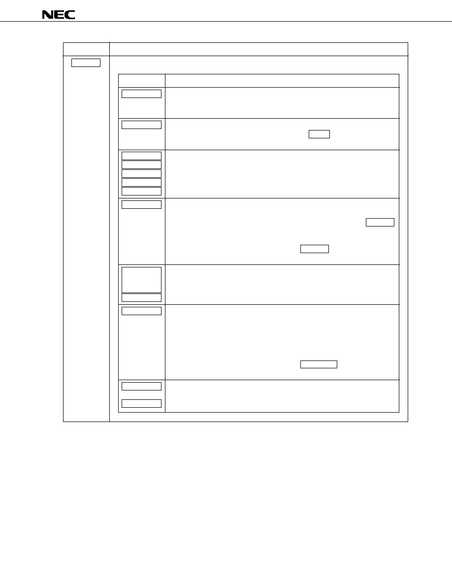
µ
PD17012GF-058
43
Momentary key
Description
P.SCAN
During the auto-storage operation, each key function as follows:
Key
Description
The auto-storage operation stops, the frequency selected when the auto-storage
operation began is received. If the auto local function is being used, local mode is
selected.
In radio, radio-monitor tape, and radio-monitor CD modes, the auto-storage
operation stops, the operation corresponding to the BAND key begins at the
frequency selected when the auto-storage operation began.
The auto-storage operation stops, the operation corresponding to the pressed key
begins at the frequency selected when the auto-storage operation began.
Either of the following operations occurs depending on what the current mode is.
(1) In radio-monitor tape and radio-monitor CD modes
The auto-storage operation stops, the operation corresponding to the RDMONI
key begins at the frequency selected when the auto-storage operation began.
(2) In radio mode
The auto-storage operation continues. The RDMONI key becomes ineffec-
tive.
The auto-storage operation continues. The operation corresponding to the pressed
key begins.
Either of the following operations occurs depending on the state of the AUTOLOC
initial setting diode.
(1) When AUTOLOC = 0:
Switching occurs between local and DX modes. All stations detected so far
are canceled.
(2) When AUTOLOC = 1:
The auto-storage operation continues. The MONO/LOC key becomes
ineffective.
The auto-storage operation stops. The set tunes itself to the frequency recorded in
the preset memory corresponding to the pressed key.
P.SCAN
BAND
SCAN UP
SCAN DWN
SEEK UP
MAN UP
MAN DWN
RDMONI
LOUD/
ILLUMI-
MATION
POWER
MONO/LOC
M1
to
M6
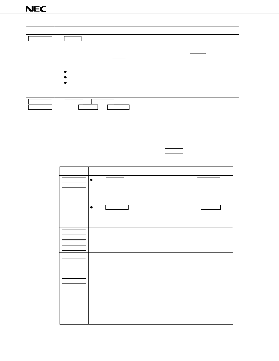
µ
PD17012GF-058
44
Momentary key
Description
RDMONI
SCAN UP
SCAN DWN
The RDMONI key controls radio monitoring. It is effective in tape, CD, radio-monitor tape, or radio-
monitor CD mode. Each time the key is pressed, radio monitor mode is set or reset. In radio monitor
mode, the "RDMONI" display on the LCD panel lights.
In radio monitor mode, tuning is enabled for all bands, the radio mute function (RDMUTE pin) is switched
off, and the audio mute function (AMUTE pin) is switched on.
Radio monitor mode is reset by:
Change in the TPSET switch state
Change in the CDSET switch state
Change at the CE pin from high level to low level
Note
Note When using alarm mode, always pull up the CE pin.
The SCAN UP and SCAN DWN keys are used for auto-tuning (scan operation).
Pressing the SCAN UP key ( SCAN DWN key) increases (decreases) the frequency by one channel
space and checks whether there is a broadcasting station at each reception frequency (frequency counter
and SD signal). If a broadcasting station is detected, the corresponding frequency is held for five seconds.
If no key is pressed within this hold time of five seconds, the seek operation restarts. If another broadcast-
ing station is detected, the corresponding frequency is held in the frequency counter for five seconds. This
operation is repeated (scan operation) sequentially.
The frequency display blinks at 1 Hz (with a duty cycle of 50%) during the five-second hold time. A beep
occurs at the end of the hold time.
The seek operation here is the same as one performed with the SEEK UP key.
The following table lists the operation corresponding to each key pressed during the seek operation (except
the hold time).
Key
Description
If the SCAN UP key is pressed in scan-up mode, or the SCAN DWN key
is pressed in scan-down mode:
The scan operation stops, and the frequency that was selected when the scan
operation began is reselected. If the auto local function is being used, local
mode is switched.
If the SCAN DWN key is pressed in scan-up mode, or the SCAN UP key
is pressed in scan-down mode:
The operation corresponding to the pressed key begins at the frequency that is
selected when the key is pressed.
The scan operation stops, and the operation corresponding to the pressed key
begins at the frequency that is selected when the key is pressed.
In radio, radio-monitor tape, and radio-monitor CD modes, the scan operation stops.
The frequency that was selected when the scan operation began (or the frequency on
hold if a broadcasting station has been detected during the scan operation) is
reselected, and the operation corresponding to the pressed key begins.
Either of the following operations occurs depending on what the current mode is.
(1) In radio-monitor tape and radio-monitor CD modes
The scan operation stops. The frequency that was selected when the scan
operation began (or the frequency on hold if a broadcasting station has been
detected during the scan operation) is reselected, and the operation corre-
sponding to the pressed key begins.
(2) In radio mode
The seek operation continues, and the key becomes an ineffective key.
SCAN UP
SCAN DWN
SEEK UP
MAN UP
MAN DWN
P.SCAN
BAND
RDMONI

µ
PD17012GF-058
45
Momentary key
Description
Key
Description
The scan operation continues, and the operation corresponding to the pressed key
begins.
Either of the following operations occurs depending on the state of the AUTOLOC
initial setting diode.
(1) When AUTOLOC = 0:
The scan operation continues, and the operation corresponding to the key
begins.
(2) When AUTOLOC = 1:
The scan operation continues, and the key becomes invalid.
The scan operation stops. The set tunes itself to the frequency recorded in the
preset memory corresponding to the pressed key.
LOUD/
ILLUMI-
NATION
POWER
MONO/LOC
M1
to
M6
SCAN UP
SCAN DWN

µ
PD17012GF-058
46
Momentary key
Description
SCAN UP
SCAN DWN
Each key functions during the five-second hold time as follows:
Key
Description
If the SCAN UP key is pressed in scan-up mode, or the SCAN DWN key
is pressed in scan-down mode:
The scan operation stops, and the frequency counter is set to the frequency on
hold.
If the SCAN DWN key is pressed in scan-up mode, or the SCAN UP key
is pressed in scan-down mode:
The operation corresponding to the pressed key begins.
The scan operation stops, and the operation corresponding to the pressed key
begins at the frequency on hold.
In radio, radio-monitor tape, and radio-monitor CD modes, the scan operation
stops. The operation corresponding to the pressed key begins at the frequency on
hold.
Either of the following operations occurs depending on what the current mode is.
(1) In radio-monitor tape and radio-monitor CD modes
The scan operation stops. The operation corresponding to the pressed key
begins at the frequency on hold.
(2) In radio mode
The seek operation continues, and the key becomes an ineffective key.
The scan operation continues. The operation corresponding to the pressed key
begins.
Either of the following operations occurs depending on the state of the AUTOLOC
initial setting diode.
(1) When AUTOLOC = 0:
The scan operation continues, and the operation corresponding to the pressed
key begins.
(2) When AUTOLOC = 1:
The scan operation continues, and the pressed key becomes an ineffective
key.
SCAN UP
SCAN DWN
SEEK UP
MAN UP
MAN DWN
P.SCAN
BAND
RDMONI
LOUD/
ILLUMI-
NATION
POWER
MONO/LOC
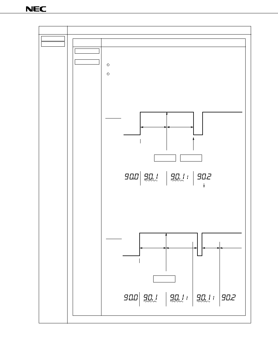
µ
PD17012GF-058
47
Momentary key
Description
Key
Description
The scan operation stops.
Either of the following operations occurs depending on the timing at which the key
is released.
If the key is released within 2 seconds:
A preset memory corresponding to the pressed key is accessed.
If the key is held pressed for at least 2 seconds:
The frequency being currently received is written to the preset memory corre-
sponding to the pressed key.
Example 1. If the key is released within 2 seconds:
The tuner is set to the frequency in the preset memory corresponding
to the pressed key when the key is released. The scan operation is
canceled.
M1
CH
Example
of display
Key pressed
RDMUTE pin
Within 5 seconds Within 2 seconds
M1
Blinking
Blinking
Hold
Hold
Seek
M1 accessed
Station detected
key pressed
key released
Content of M1
Example
2. If the key is pressed for at least 2 seconds:
When the key is pressed for 2 seconds, the frequency on hold is
written to the preset memory corresponding to the pressed key. The
hold state is released 2 seconds after the writing to the preset
memory, and a search (seek operation) for another station begins.
M1
CH
Example
of display
Key pressed
RDMUTE pin
Within 5 seconds
2 seconds
Blinking
Blinking
Hold
Hold
2 seconds
Hold
Blinking
CH
Seek
Seek
Station detected
held pressed
M1
to
M6
SCAN UP
SCAN DWN
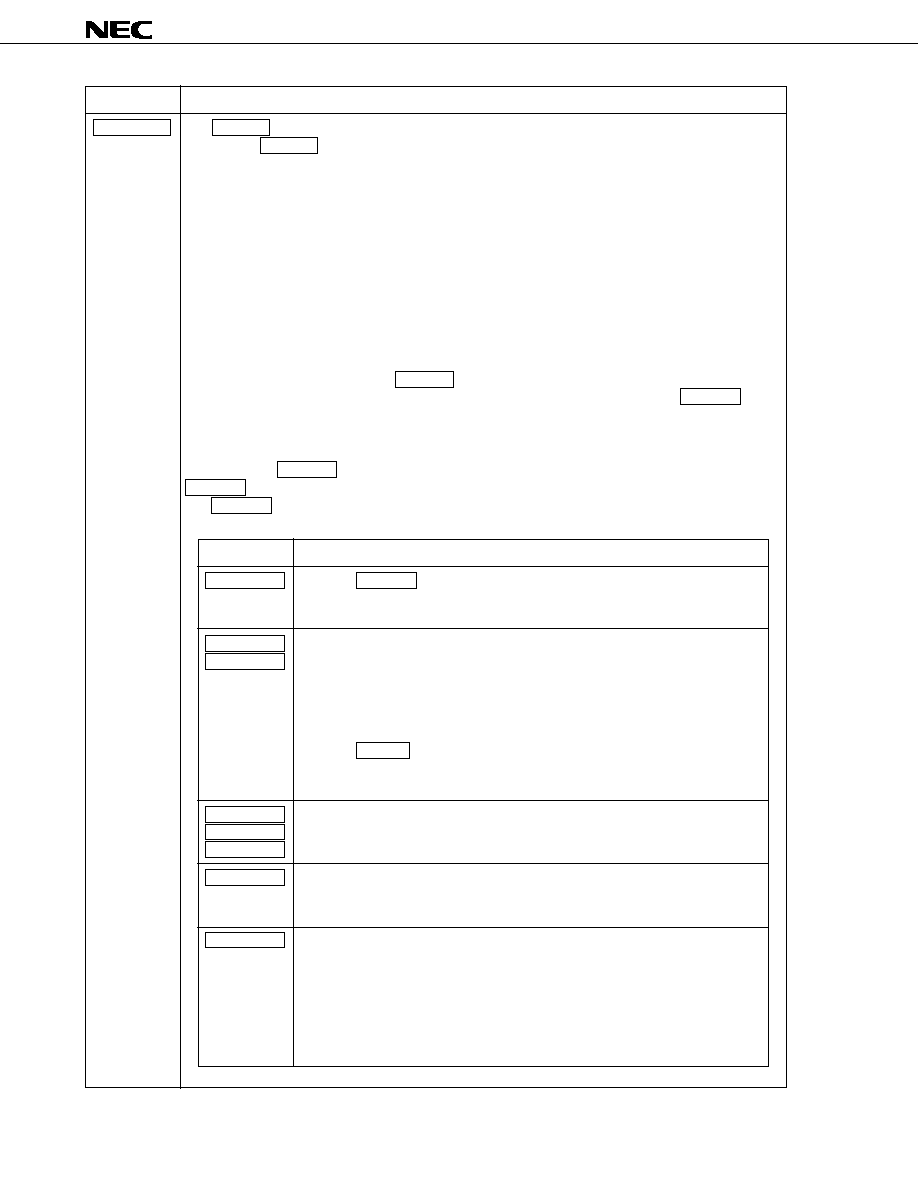
µ
PD17012GF-058
48
Momentary key
Description
SEEK UP
The SEEK UP key is used for auto-tuning (seek operation).
Pressing the SEEK UP key increases the frequency by one channel space and checks whether there is a
broadcasting station at each reception frequency (by a method determined depending on the states of the
ENAMIF and ENFMIF initial setting diodes). If a broadcasting station is detected, the seek operation ends.
The seek operation performed varies with the state of the AUTOLOC initial setting diode as follows:
(1) When AUTOLOC = 0 (with no auto local function):
A search operation begins at the frequency currently being received.
The search operation continues in local or DX mode whichever has been selected when the search
operation starts, until a station is detected.
(2) When AUTOLOC = 1 (with an auto local function):
A search operation begins at the frequency being currently received in local mode. When all frequen-
cies are searched through in local mode, a search operation is switched to DX mode and continues
until a station is detected. If the SEEK UP key is pressed in local mode, DX mode is selected, and a
search operation restarts with the same frequency as for the previous search. If the SEEK UP key is
pressed during a search in DX mode, the search operation ends, and the frequency at which the
search operation began is selected.
When using the SEEK UP key, set the AUTO500 initial setting diode to 0. Setting it to 1 disables the
SEEK UP key.
The SEEK UP key functions during the search operation as follows:
Key
Description
When the SEEK UP key is pressed in seek-up mode, the seek operation stops,
and the frequency at which the search operation began is selected. If the auto
local function is being used when the key is pressed, local mode is switched.
One of the following operations occurs depending on the state of the AUTO500
initial setting diode.
(1) When AUTO500 = 0:
A manual tuning operation begins at the frequency that is in the frequency
counter when the key is pressed.
(2) When AUTO500 = 1:
If the MAN UP key is pressed in seek-up mode, the seek operation stops,
and the frequency that was selected when the seek operation began is
reselected. If the auto local function is being used, local mode is switched.
The seek operation stops, and the operation corresponding to the pressed key
begins at the frequency that was selected when the key was pressed.
In radio, radio-monitor tape, and radio-monitor CD modes, the seek operation
stops. The frequency that was selected when the seek operation began is
reselected, and the operation corresponding to the pressed key begins.
Either of the following operations occurs according to what the current mode is.
(1) In radio-monitor tape and radio-monitor CD modes
The seek operation stops. The frequency that was selected when the seek
operation began is reselected, and the operation corresponding to the pressed
key begins.
(2) In radio mode
The seek operation continues, and the key becomes an ineffective key.
SEEK UP
MAN UP
MAN DWN
SCAN UP
SCAN DWN
P.SCAN
BAND
RDMONI
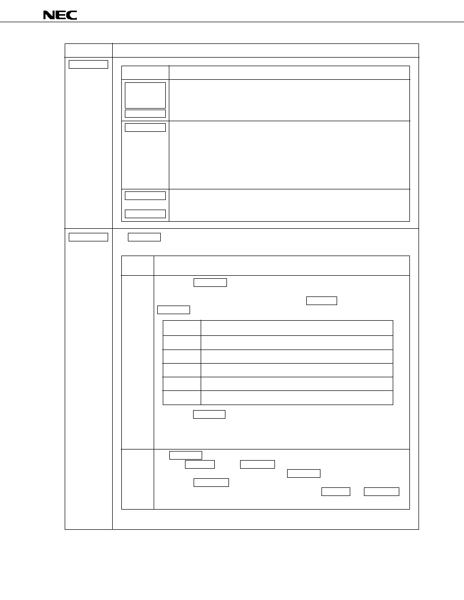
µ
PD17012GF-058
49
Momentary key
Description
Key
Description
The seek operation continues, and the operation corresponding to the pressed key
begins.
Either of the following operations occurs depending on the state of the AUTOLOC
initial setting diode.
(1) When AUTOLOC = 0:
The seek operation continues, and the operation corresponding to the key
begins.
(2) When AUTOLOC = 1:
The seek operation continues, and the pressed key becomes invalid.
The seek operation stops. The set tunes itself to the frequency recorded in the
preset memory corresponding to the pressed key.
LOUD/
ILLUMI-
NATION
POWER
MONO/LOC
M1
to
M6
SEEK UP
VOL DWN
The VOL DWN key is used to adjust the volume of sound in each electronic volume control mode. The
operation depends on the state of the VKYSEL initial setting diode.
(1: Shorted by the diode; 0: Open)
VKYSEL
0
1
Description
Pressing the VOL DWN key in a mode other than an electronic volume control mode
selects volume mode and increases the volume of sound.
In an electronic volume control mode selected by the VOL SEL key, pressing the
VOL DWN key activates the operation corresponding to the selected mode as follows:
Keeping the VOL DWN key pressed for at least 0.5 seconds controls the volume
continuously.
If no key is pressed for at least 3 seconds, the mode previous to the current electronic
volume control mode is reselected.
The VOL DWN key is ineffective. After an electronic volume control mode is selected
using the VOL SEL key, the MAN DWN key can be used to perform the same
adjustment that would be performed using the VOL DWN key.
Pressing the MAN DWN key in a mode other than an electronic volume control mode
does not select volume mode. See the descriptions of the MAN UP and MAN DWN
keys for details.
Volume
Bass
Treble
Balance
Fader
Mode
Decreases the main sound volume.
Decreases the bass.
Decreases the treble.
Emphasizes the sound volume from the left-side speaker.
Emphasizes the sound volume from the rear speaker.
Function

µ
PD17012GF-058
50
Momentary key
Description
VOL SEL
The VOL SEL key is used to select an electronic volume control mode. There are five electronic volume
control modes as listed below:
Either of the modes listed below is selected depending on the state of the VKYSEL initial setting diode.
Each time the VOL SEL key is pressed, the mode switches as listed below.
(1: Shorted by the diode; 0: Open)
Mode
Volume
Bass
Treble
Balance
Fader
Panel display
(initial setting)
Function
Controls the main sound volume.
Controls the bass.
Controls the treble.
Controls the sound volume from the right- and left-side
speakers.
Controls the sound volume from the front and rear speakers.
VKYSEL
0
1
Description
The first mode selected is bass mode.
VOL SEL
Bass
Tremble
Balance
Volume
Fader
START
1 PUSH
The first mode selected is volume mode.
VOL SEL
Volume
Bass
Treble
Fader
Balance
START
1 PUSH

µ
PD17012GF-058
51
Momentary key
Description
VOL UP
The VOL UP key is used to adjust the volume of sound in each electronic volume control mode. The
operation depends on the state of the VKYSEL initial setting diode.
(1: Shorted by the diode; 0: Open)
VKYSEL
0
1
Description
Pressing the VOL UP key in a mode other than an electronic volume control mode
selects volume mode and increases the volume of sound.
In an electronic volume control mode selected by the VOL SEL key, pressing the
VOL UP key activates the operation corresponding to the selected mode as follows:
Keeping the VOL UP key pressed for at least 0.5 seconds controls the volume continu-
ously.
If no key is pressed for at least 3 seconds, the mode previous to the current electronic
volume control mode is reselected.
The VOL UP key is ineffective. After an electronic volume control mode is selected
using the VOL SEL key, the MAN UP key can be used to perform the same adjust-
ment that would be performed using the VOL UP key.
Pressing the MAN UP key in a mode other than an electronic volume control mode
does not select volume mode. See the descriptions of the MAN UP and MAN DWN
keys for details.
Volume
Bass
Treble
Balance
Fader
Mode
Increases the main sound volume.
Increases the bass.
Increases the treble.
Emphasizes the sound volume from the right-side speaker.
Emphasizes the sound volume from the front speaker.
Function

µ
PD17012GF-058
52
3. ALARM FUNCTION
The alarm function is provided as a means of preventing car theft. If the alarm system detects anyone other than
the user entering the car, a warning sound is generated.
3.1 Overview of the Alarm Function
∑
When alarm mode is off
∑
When alarm mode is on
The door is
opened
The signal indicating
an open door is
recognized.
The ignition switch
is turned on
The IGNITION pin
becomes high.
Alarm mode is
released
Power-on
enabled state
The door is
opened
The signal indicating
an open door is
recognized.
Entry time
elapses
If the ignition switch
is not turned on
within entry time
Alarm mode is
released
An alarm is
generated
A beep is output
from the BEEP
pin with electronic
volume output
maximized.
Reset time
elapsed
Power is
turned off
Power-on
enabled state
When the ignition
switch is turned on
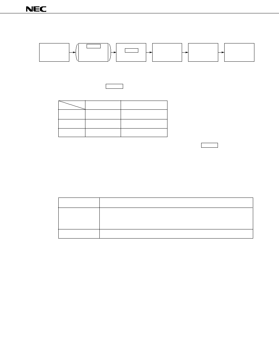
µ
PD17012GF-058
53
3.2 Setting Alarm Mode
Alarm mode is set as follows:
Note
The time for each status can be set in this stage.
Press and hold down the P.SCAN key for two seconds. Then each time the key is pressed, the status
changes in the order of the exit time, entry time, reset time, and setting end.
Initial value (s)
Specificate value (s)
Exit time
12
3 to 180
Entry time
12
3 to 180
Reset time
30
3 to 180
Exit time
: Time between opening and closing the door after pressing the ALARM key
Entry time : Time between opening the door and turning on the ignition switch
Reset time : Time during which an alarm sound is generated in alarm mode
To set alarm mode, the following pins and keys in (1) to (7) are used.
(1) IGNITION pin
The ignition switch signal is input from the key box.
IGNITION pin
State
At the low level
∑ Power-off
∑ Alarm mode on (alarm being output) and alarm mode time setting enabled
∑ In alarm mode
At the high level
Power-on enabled state
The P.SCAN key
is pressed and
held down for two
seconds
Note
The ignition switch
is turned off
The IGNITION pin
goes low.
The ALARM key
is pressed
Alarm mode enabled
state
The user gets
out of the car
The door is
closed
After recognizing
the signal indicating
a closed door, alarm
mode is selected
The door is
opened
The signal indicating
an open door is
recognized.
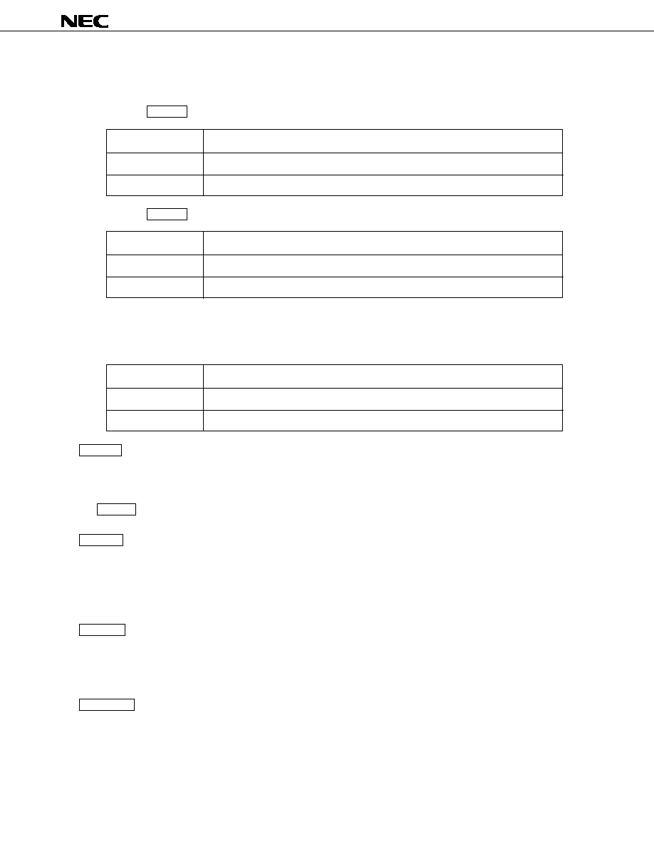
µ
PD17012GF-058
54
(2) ALARMIN pin
The signal indicating that the car door is open or closed is input.
∑ When the ALARM key has been turned on with the ALARMIN pin at the low level
ALARMIN pin
State
At the low level
The door is closed.
At the high level
The door is open.
∑ When the ALARM key has been turned on with the ALARMIN pin at the high level
ALARMIN pin
State
At the low level
The door is open.
At the high level
The door is closed.
(3) ALARMOUT pin
The state upon warning is output.
This pin is used as a power-on signal for the peripheral hardware, such as an electronic volume control or amplifier.
ALARMIN pin
State
At the low level
Alarm mode off
At the high level
Alarm mode on (alarm being output)
(4) ALARM key
When this key is pressed with both of the following conditions satisfied, the alarm function is activated.
∑ The ignition switch is off.
∑ The DISALARM initial setting diode is set to 0.
The ALARM key is effective only when the IGNITION pin = 0.
(5) P.SCAN key
When this key is pressed and held down for two seconds or more with both of the following conditions satisfied,
the system enters the alarm time setting state.
∑ The ignition switch is off.
∑ The DISALARM initial setting diode is set to 0.
(6) MAN UP key
When this key is pressed in the alarm time setting state, the set time is incremented by one step (one second).
When this key is pressed and held down for two seconds or more, the set time is incremented continuously at
a rate of one step per 50 ms.
(7) MAN DWN key
When this key is pressed in the alarm time setting state, the set time is decremented by one step (one second).
When this key is pressed and held down for two seconds or more, the set time is decremented continuously at
a rate of one step per 50 ms.
Figure 3-1 outlines the setting and operation of alarm mode. Figures 3-2 to 3-4 show the transition of the alarm
operations.

µ
PD17012GF-058
55
Figure 3-1. Outline of Setting and Operation of Alarm Mode
Note
0: Alarm operation being halted
1: During alarm time setting (setting of the time for exit, entry, and reset)
2: During exit operation
3: During entry checking
4: During entry operation
5: Alarm being generated
See Figure 3-2.
The ignition switch
is turned off
The P.SCAN key is
pressed and held down
for two seconds
ALARM key
(Setting the time)
See Figure 3-4.
(Exit mode)
Exit time elapsed
(Exit mode continues while the door is open)
Opening of the door is detected
Entry time elapsed
(Entry
checking)
(Entry mode)
(An alarm is generated)
Reset time elapsed
0
1
2
3
4
5
Alarm mode
Note
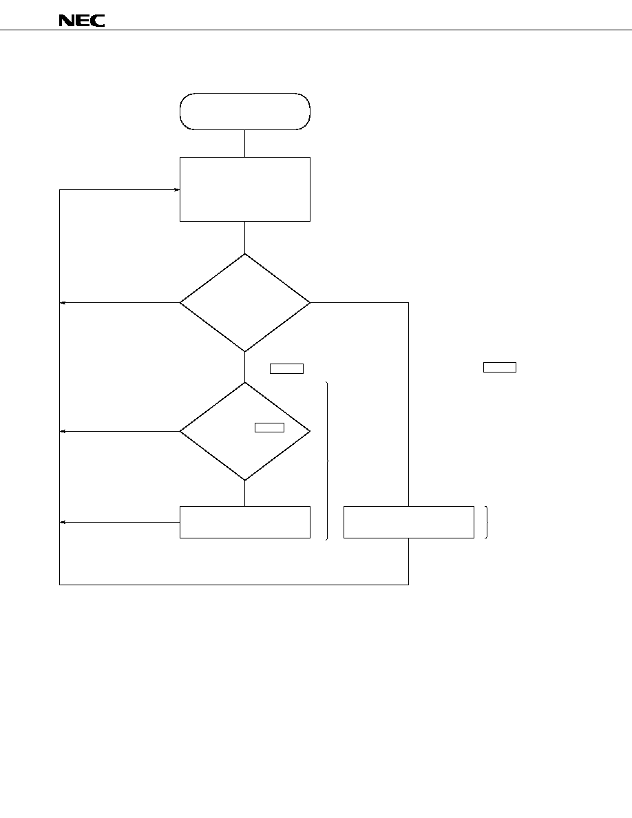
µ
PD17012GF-058
56
Figure 3-2. Transition of Alarm Operations 1 (While Alarm Operation Is Halted)
The ignition switch is turned off
Halt
(When an alarm is enabled:
DISALARM = 0)
Reads key input
Checks whether the P.SCAN key
is held down for two seconds
Alarm time setting
Alarm function processing
No key
Released within two seconds
Setting completed
Key input
Check for
the P.SCAN
key
Held down for
two seconds
See Figure 3-3.
Check for the ALARM key
See Figure 3-4.
End of alarm processing
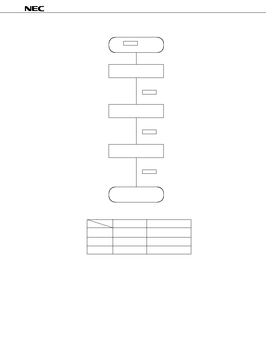
µ
PD17012GF-058
57
Figure 3-3. Transition of Alarm Operations 2 (Alarm Time Setting)
Initial value (s)
Specifiable value (s)
Exit time
12
3 to 180
Entry time
12
3 to 180
Reset time
30
3 to 180
The P.SCAN key is held
down for two seconds
Set exit time
Set entry time
Set reset time
Alarm time setting is completed
P.SCAN key
(Set values are saved)
P.SCAN key
P.SCAN key
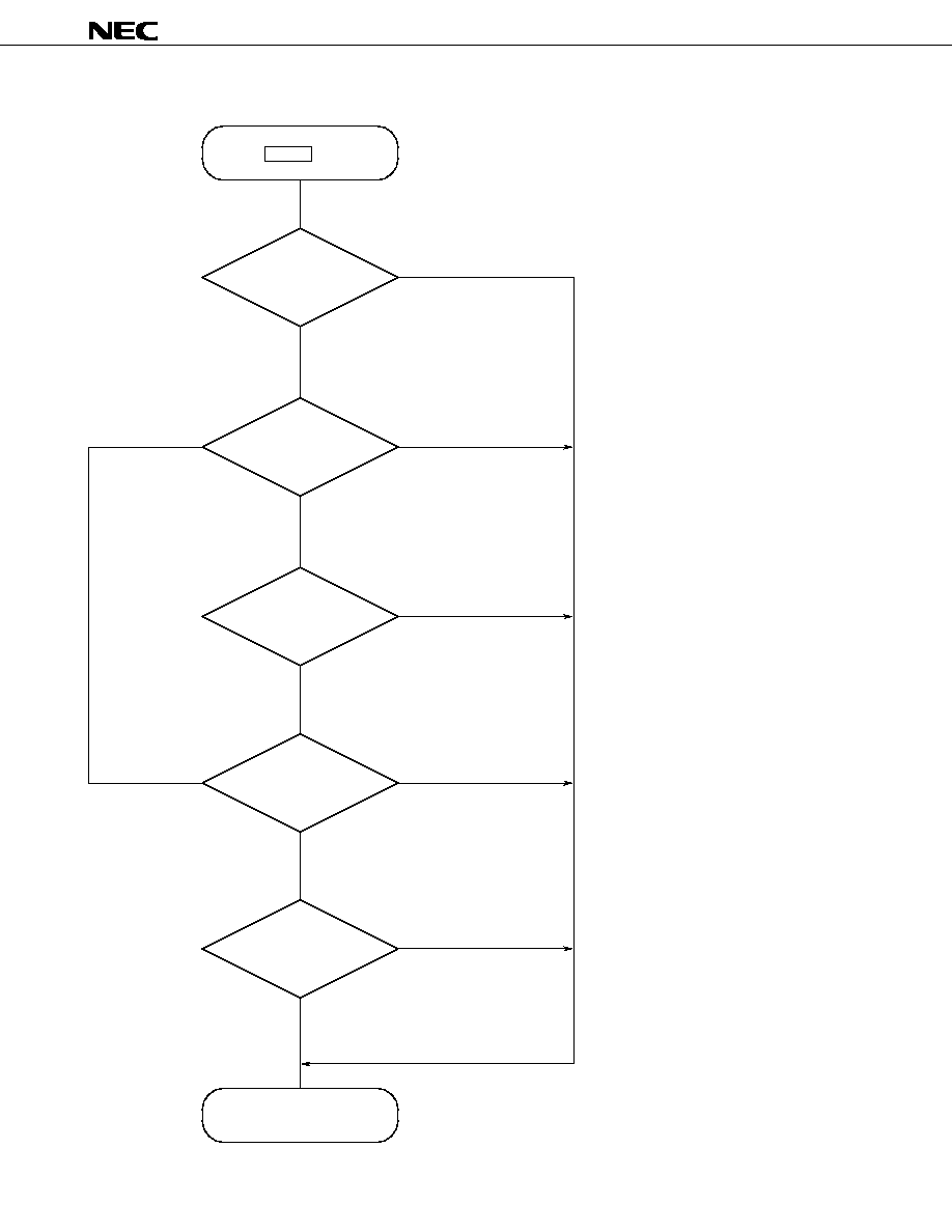
µ
PD17012GF-058
58
Figure 3-4. Transition of Alarm Operations 3 (During Alarm Function Processing)
ALARM key
Exit mode
"ALA" is displayed
for 10 seconds
Halt
Entry mode
Alarm mode
Alarm time setting completed
The ignition switch is turned on
Exit time elapsed
(confirmation of closing the door)
The ignition switch is turned on
The ignition switch is turned on
The ignition switch is turned on
Ten seconds elapsed
The door is opened
Entry time elapsed
<Exit mode>
Waits for the specified exit time.
Upon the completion of the wait,
checks that the door is closed
and displays "ALA."
<"ALA" is displayed for 10 seconds>
"ALA" is displayed for 10 seconds.
When an open door is detected within
this 10 seconds, entry mode is selected.
<Halt>
The door switch is checked every 100 ms.
When an open door is detected, entry mode
is selected.
<Entry mode>
A beep is output every 0.5 second.
Once the specified time elapses,
alarm mode is selected.
<Alarm mode>
Electronic volume output is maximized
and a special beep is output.
Alarm-out output is at the high level.
Once the specified time elapses,
alarm processing is terminated.
Reset time elapsed
The door is opened
The ignition switch is turned on

µ
PD17012GF-058
59
4. MODE TRANSITION
The radio set is turned on or off by switching the RDSET switch.
The RDSET, TPSET, and CDSET switches are enabled only when the CE and IGNITION pins are high.
When the IGNITION pin is made low, clock display is not provided regardless of state of the initial setting diode
NOCLK. However, when NOCLK = 0 (for using the clock), the clock operates.
Transition to alarm mode is possible when the IGNITION pin is at a low level.
The CE pin must be fixed to a high level.
(1) Mode transition when the IGNITION pin is raised from low to high
The RDSET switch is used to turn on or off radio mode.
The TPSET and CDSET switches are used to switch to tape mode and CD mode.
Remark The numbers in brackets (< >) represent the following:
<1>: CDSET switch on
<2>: CDSET switch off
<3>: TPSET switch on
<4>: TPSET switch off
<5>: RDSET switch on
<6>: RDSET switch off
<7>: IGNITION pin off (low level)
<8>: ALARM key on
<9>: DISALARM switch = 0
<2><3> <2><4><5>
<2><4><6>
<1>
IGNITION = low
The function is
disabled.
Alarm mode
IGNITION = low
high
Wait for 100 ms
maximum
Tape mode
Radio mode
Power-off mode
CD mode
<7><8><9>
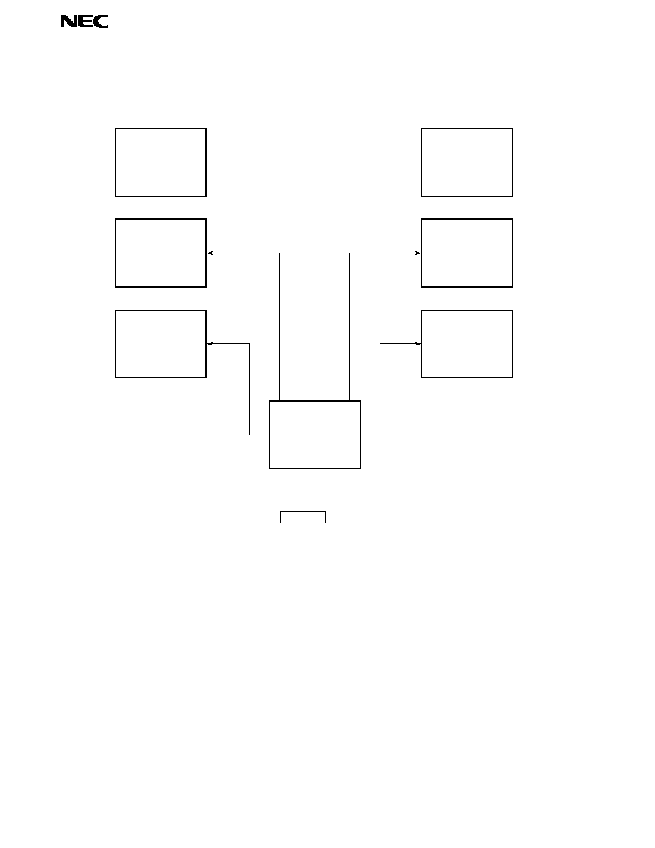
µ
PD17012GF-058
60
(2) Mode transition when the IGNITION pin is held high
(a) Transition from radio mode to another mode
Remark The numbers in brackets (< >) represent the following:
<1>: CDSET switch on
<5>: RDMONI key on
<2>: CDSET switch off
<6>: RDSET switch on
<3>: TPSET switch on
<7>: RDSET switch off
<4>: TPSET switch off
<8>: Electronic volume control key on
<7>
<3>
<8>
<1>
Radio-monitor
tape mode
Tape mode
Power-off mode
Radio mode
Radio-monitor
CD mode
CD mode
Electronic volume
control mode
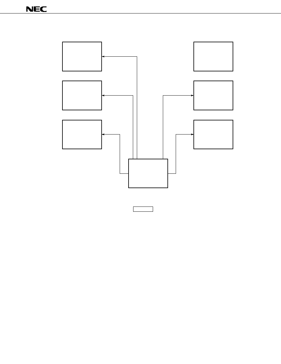
µ
PD17012GF-058
61
(b) Transition from tape mode to another mode
Remark The numbers in brackets (< >) represent the following:
<1>: CDSET switch on
<5>: RDMONI key on
<2>: CDSET switch off
<6>: RDSET switch on
<3>: TPSET switch on
<7>: RDSET switch off
<4>: TPSET switch off
<8>: Electronic volume control key on
<4><7>
<4><6>
<5>
<8>
<1>
Radio-monitor
tape mode
Radio mode
Power-off mode
Tape mode
Radio-monitor
CD mode
CD mode
Electronic volume
control mode
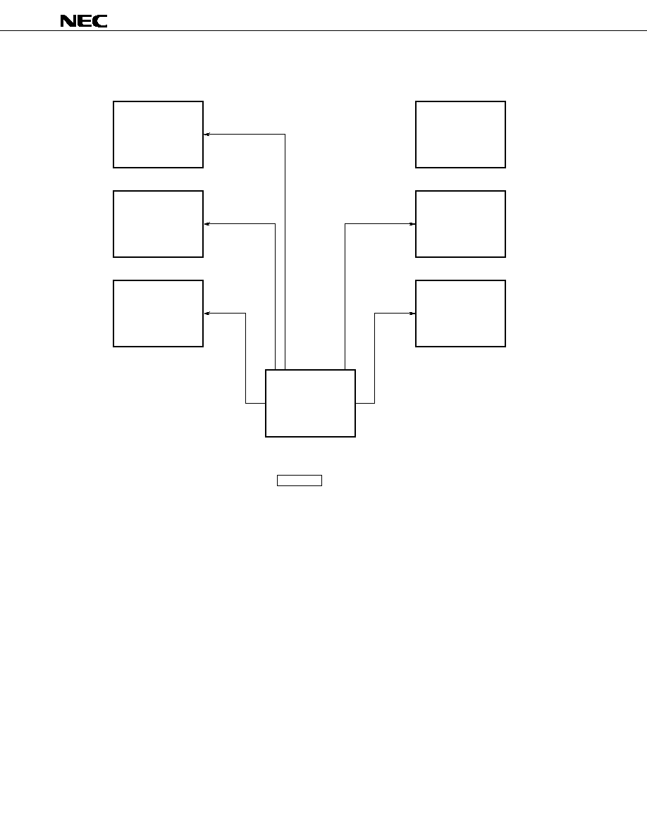
µ
PD17012GF-058
62
(c) Transition from radio-monitor tape mode to another mode
Remark The numbers in brackets (< >) represent the following:
<1>: CDSET switch on
<5>: RDMONI key on
<2>: CDSET switch off
<6>: RDSET switch on
<3>: TPSET switch on
<7>: RDSET switch off
<4>: TPSET switch off
<8>: Electronic volume control key on
<4><7>
<5>
<4><6>
<8>
<1>
Tape mode
Power-off mode
Radio-monitor
tape mode
Radio-monitor
CD mode
CD mode
Electronic volume
control mode
Radio mode
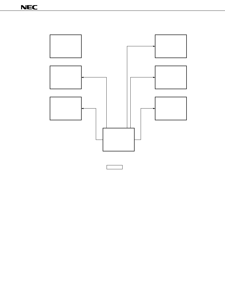
µ
PD17012GF-058
63
(d) Transition from CD mode to another mode
Remark The numbers in brackets (< >) represent the following:
<1>: CDSET switch on
<5>: RDMONI key on
<2>: CDSET switch off
<6>: RDSET switch on
<3>: TPSET switch on
<7>: RDSET switch off
<4>: TPSET switch off
<8>: Electronic volume control key on
<2><4><7>
<2><3>
<8>
<2><4><6>
<5>
Radio-monitor
tape mode
Tape mode
Power-off mode
CD mode
Radio-monitor
CD mode
Radio mode
Electronic volume
control mode

µ
PD17012GF-058
64
(e) Transition from radio-monitor CD mode to another mode
Remark The numbers in brackets (< >) represent the following:
<1>: CDSET switch on
<5>: RDMONI key on
<2>: CDSET switch off
<6>: RDSET switch on
<3>: TPSET switch on
<7>: RDSET switch off
<4>: TPSET switch off
<8>: Electronic volume control key on
<2><4><7>
<8>
<5>
<2><4><6>
<2><3>
Radio-monitor
tape mode
Tape mode
Power-off mode
Radio-monitor
CD mode
CD mode
Electronic volume
control mode
Radio mode

µ
PD17012GF-058
65
(f)
Transition from power-off mode to another mode
Remark The numbers in brackets (< >) represent the following:
<1>: CDSET switch on
<5>: RDMONI key on
<2>: CDSET switch off
<6>: RDSET switch on
<3>: TPSET switch on
<7>: RDSET switch off
<4>: TPSET switch off
<8>: Electronic volume control key on
<6>
<1>
<3>
Radio-monitor
tape mode
Tape mode
Radio mode
Radio-monitor
CD mode
CD mode
Electronic volume
control mode
Power-off mode

µ
PD17012GF-058
66
5. DISPLAY
5.1 LCD Panel
POP
FM 1
FM 2
FM 3
MW LW
CLASSIC
NORMAL
ROCK
MONO
AM
CH PM
MTL
ST
RESET
ALARM
ARMING EXIT
ENTRY
RDMONI
LOUD
LOC
5.2 Character Style
5.3 Examples of Display
(1) Tape mode
(4) Volume mode
(7) Balance mode
(2) CD mode
(5) Bass mode
(8) Fader mode
(3) Auto-storage
(6) Treble mode
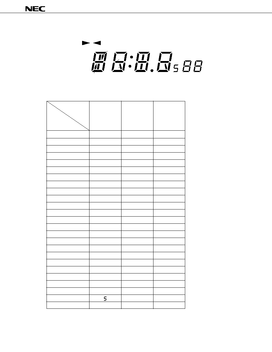
µ
PD17012GF-058
67
5.4 LCD Assignment
AM
CH PM
FM 1
FM 2
FM 3
MW LW
a
f
e
l d
1
2
3
4
5
6
i
b
c
g
h
j
k
CLASSIC
NORMAL
ROCK
MONO
MTL
ST
POP
RESET
ALARM
ARMING EXIT
ENTRY
RDMONI
LOUD
LOC
5.5 Pin Assignment of the LCD Controller/Driver (
µ
PD7225)
Remark The numbers in parentheses indicate the pin numbers of the
µ
PD7225G (52-pin plastic QFP).
Pin name
(pin number)
S0 (19)
S1 (20)
S2 (21)
S3 (22)
S4 (23)
S5 (24)
S6 (25)
S7 (26)
S8 (27)
S9 (28)
S10 (29)
S11 (30)
S12 (31)
S13 (32)
S14 (34)
S15 (35)
S16 (36)
S17 (37)
S18 (38)
S19 (39)
S20 (40)
S21 (41)
S22 (42)
S23 (43)
S24 (44)
ST
POP
1l, i
1g
1k, h
ALARM
2g
2j
:
3g
3h, k
.
4g
4j
AM
ARMING
5g
EXIT
ENTRY
6g
RESET
RDMONI
ROCK
MW
LW
FM3
1d
1e
1c
2e
2d
2c
3e
3d
3c
4e
4d
4c
PM
5e
5d
5c
6e
6d
6c
CH
NORMAL
CLASSIC
FM1
FM2
1f
1a
1b
2f
2a
2b
3f
3a
3b
4f
4a
4b
MONO
5f
5a
5b
6f
6a
6b
MTL
LOUD
LOC
Pin name (pin
number)
COM0 (15)
COM1 (16)
COM2 (17)
v
v
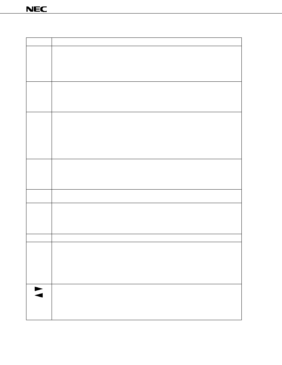
µ
PD17012GF-058
68
5.6 Description of Display
Display
Description
ALARM
ARMING
EXIT
ENTRY
RESET
CLASSIC
NORMAL
POP
ROCK
ST
LOC
LOUD
MTL
RDMONI
MONO
Indicates the state of the alarm operation.
∑ ALARM
: This indication is on in alarm mode.
∑ ARMING : This indication is on during alarm output.
∑ EXIT
: This indication is on during exit time setting.
∑ ENTRY
: This indication is on during entry time setting.
∑ RESET
: This indication is on during reset time setting.
Indicates the mode for the external sound control IC.
∑ CLASSIC : Classic mode
∑ NORMAL : Normal mode
∑ POP
: Pops mode
∑ ROCK
: Rock mode
Indicates that a stereo broadcast is currently received.
(1) In CD mode or tape mode
This indication is off.
(2) In other modes
This indication is on when the FM or MW band is selected, the ST switch is on in the station reception
state, and the MONO-off state is set. (For the MW band, this indication is on only when the initial setting
diode MWS = 1, and the stereo reception function is enabled.)
This indication is off during tuning operation regardless of which band is selected.
Indicates that the local state is set.
(1) In CD mode and tape mode
This indication is off.
(2) In other modes
This indication is on in the local state.
Indicates that the loudness-on state is set.
This indication is on in the loudness-on state, regardless of which mode is set.
Indicates that the METAL-on state is set.
(1) In tape mode and radio-monitor tape mode
This indication is on in the METAL-on state.
(2) In other modes
This indication is off.
Indicates that the radio-monitor state is set.
Indicates that the MONO state is set.
(1) In CD mode and tape mode
This indication is off.
(2) In other modes
This indication is on when the FM or MW band is selected in the MONO-off state. (For the MW band,
this indication is on only when the initial setting diode MWS = 1, and the stereo reception function is
enabled.)
Indicates a tape running direction.
(1) In tape mode and radio-monitor tape mode
A tape running direction is displayed according to the state of the RL switch. A tape running direction
blinks when the FF switch is on.
(2) In other modes
This indication is off.

µ
PD17012GF-058
69
Indicates a band received.
(1) In CD mode and tape mode
This indication is off.
(2) In other modes
The band currently received is displayed.
Displays a receive frequency, "
", "
", "
", "
", "
", "
", "
", "
", and the clock.
When the entire panel is blinking while "
" is displayed, the mute state is set.
Indicates AM (before noon) or PM (after noon) when the 12-hour system is used for display.
Indicates a preset memory number or electronic volume control value.
When a preset memory is written to or called, the preset memory number is displayed together with "CH." In
a electronic volume control mode, the value of the volume control is displayed; the "CH" is turned off in this
case.
This indication is on when a frequency is displayed; this indication is off when the clock is displayed.
When preset memory write operation is enabled, "CH" blinks at a frequency of 1 Hz.
When a preset memory is being scanned, the preset memory number blinks at a frequency of 1 Hz.
Display
Description
FM1
FM2
FM3
MW
LW
AM
PM
CH

µ
PD17012GF-058
70
6. REMOTE CONTROL FUNCTION
Use the
µ
PD6121G for sending signals from a remote-controller. The
µ
PD6121G incorporates a custom code.
If this code is not correctly set, the
µ
PD17012GF-058 cannot be controlled using the remote controller.
The custom code which operates the
µ
PD17012GF-058 is 8604H. Set the code to 8604H by connecting a diode
and a pull-up resistor appropriately on the key matrix of the
µ
PD6121G. (See Section 6.4.)
6.1 Remote-Controller Key Placement (When the
µ
PD6121G Is Used)
Output pin
(pin number)
KI/O
0
(19)
KI/O
1
(18)
KI/O
2
(17)
KI/O
3
(16)
KI/O
4
(15)
KI/O
5
(14)
KI/O
6
(13)
KI/O
7
(12)
M1
M5
SCAN UP
MODE
ILLUMINATION
DISP
-
VOL UP
M2
M6
SCAN DWN
LOC
LOUD
MAN UP
-
VOL DWN
M3
SEEK UP
P. SCAN
MONO
-
MAN DWN
MTL
MUTE
Input pin (pin
number)
KI
0
(1)
KI
1
(2)
KI
2
(3)
M4
-
BAND
POWER
-
-
VOL CON
CD
KI
3
(4)

µ
PD17012GF-058
71
6.2 Remote-Controller Keys
The remote-controller keys operate in the same way as the momentary keys of the
µ
PD17012GF-058.
6.3 Remote-Controller Data Codes
∑
When each key is pressed independently
∑
When two keys are pressed simultaneously
D0
D1
D2
D3
D4
D5
D6
D7
M1
0
0
0
0
0
0
0
0
M2
1
0
0
0
0
0
0
0
M3
0
1
0
0
0
0
0
0
M4
1
1
0
0
0
0
0
0
M5
0
0
1
0
0
0
0
0
M6
1
0
1
0
0
0
0
0
SEEK UP
0
1
1
0
0
0
0
0
-
1
1
1
0
0
0
0
0
SCAN UP
0
0
0
1
0
0
0
0
SCAN DWN
1
0
0
1
0
0
0
0
P. SCAN
0
1
0
1
0
0
0
0
BAND
1
1
0
1
0
0
0
0
MODE
0
0
1
1
0
0
0
0
LOC
1
0
1
1
0
0
0
0
MONO
0
1
1
1
0
0
0
0
POWER
1
1
1
1
0
0
0
0
Remote-
controller key
Data code
D0
D1
D2
D3
D4
D5
D6
D7
ILLUMINATION
0
0
0
0
1
0
0
0
LOUD
1
0
0
0
1
0
0
0
-
0
1
0
0
1
0
0
0
-
1
1
0
0
1
0
0
0
DISP
0
0
1
0
1
0
0
0
MAN UP
1
0
1
0
1
0
0
0
MAN DWN
0
1
1
0
1
0
0
0
-
1
1
1
0
1
0
0
0
-
0
0
0
1
1
0
0
0
-
1
0
0
1
1
0
0
0
MTL
0
1
0
1
1
0
0
0
VOL CON
1
1
0
1
1
0
0
0
VOL UP
0
0
1
1
1
0
0
0
VOL DWN
1
0
1
1
1
0
0
0
MUTE
0
1
1
1
1
0
0
0
CD
1
1
1
1
1
0
0
0
Remote-
controller key
Data code
D0
D1
D2
D3
D4
D5
D6
D7
MAN UP
1
0
1
0
1
1
0
0
MAN DWN
0
1
1
0
1
1
0
0
Data code
Remote-controller key
DISP
DISP
+
+
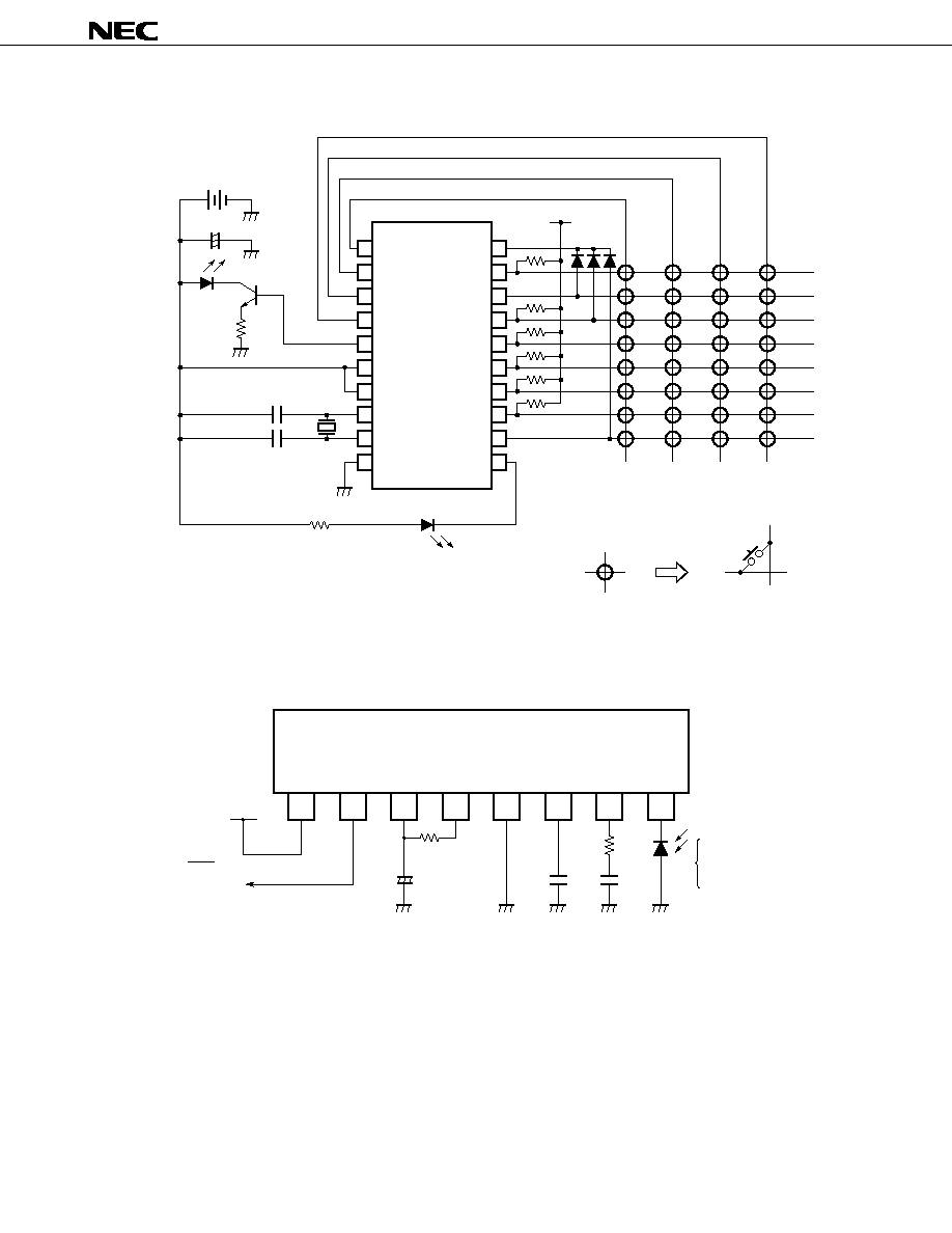
µ
PD17012GF-058
72
6.4 Example of a Remote-Controller Circuit Using the
µ
PD6121G-001
M4
BAND
POWER
VOL
CON
CD
1
2
3
4
5
6
7
8
9
10
20
19
18
17
16
15
14
13
12
11
3 V
47 F
µ
+
≠
SE303A
2SC2001
Infrared light
emitting diode
2.0
220 pF
220 pF
455 kHz
1 k
LED for indicating transmission
KI
0
KI
1
KI
2
KI
3
REM
V
DD
SEL
OSCO
OSCI
V
SS
CCS
KI/O
0
KI/O
1
KI/O
2
KI/O
3
KI/O
4
KI/O
5
KI/O
6
KI/O
7
LMP
V
DD
M1
M5
SCAN
UP
MODE
ILLUMI-
NATION
DISP
VOL
UP
M2
M6
SCAN
DWN
LOC
LOUD
MAN
UP
VOL
DWN
M3
SEEK
UP
P.
SCAN
MONO
MAN
DWN
MTL
MUTE
PD6121G-001
µ
6.5 Example of a Remote-Controller Preamplifier Circuit Using the
µ
PC2800HA
1
V
cc
1
2
OUT
3
V
cc
2
4
f
O
5
GND
6
C
D
7
IN≠
8
IN+
+5 V
PC2800HA
µ
130 k
47
F
µ
0 to
1 k
0.01
F
0.01
F
PIN
photo-diode
PH302
PH302B,
PH302C,
PH310,
and others
PD17012GF-058
µ
To the REM pin
(pin 64) of
µ
µ
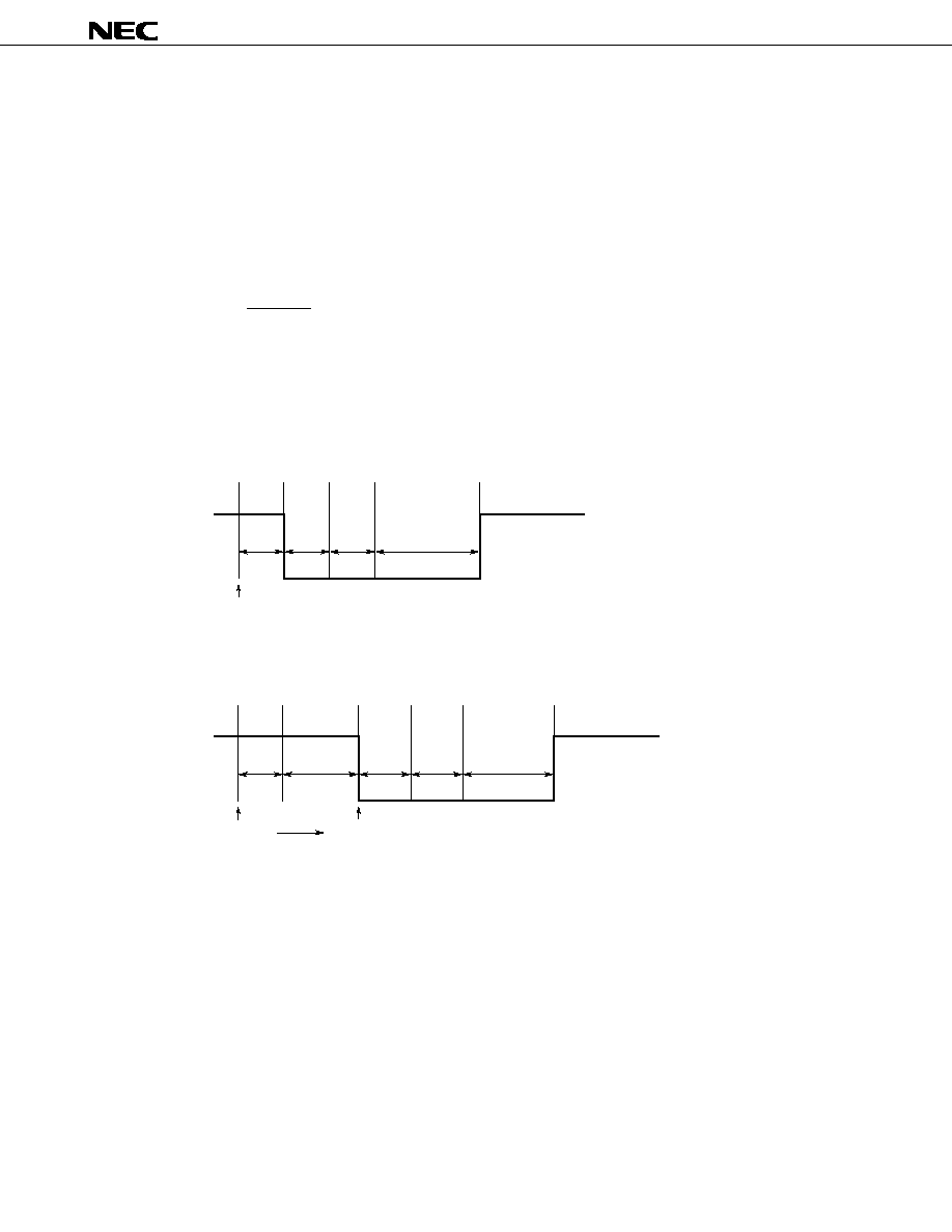
µ
PD17012GF-058
73
7. MUTE OUTPUT TIMING CHARTS
The numbers <1> through <6> in this chapter represent the following:
<1>: Key-on chattering protection
<2>: Preceding mute and beep output
<3>: Updating of the frequency division ratio setting and indication
<4>: Following mute
<5>: Scan time
<6>: Wait for PLL locking
7.1 Radio Mute (RDMUTE Pin) Output Timing Charts
(1) Manual up/down
(a) 1-channel up/down
(i) When AUTO500 switch = 0
<2>
<3>
<4>
40 ms
200 - 300 ms
15 ms
<1>
Key on
(ii) When AUTO500 switch = 1
<1>
<2>
<3>
<4>
15 ms
40 ms
200 - 300 ms
0.5 second
or less
Key on
Key off
In either case (i) or case (ii), the time of <4> is 600 ms to 700 ms at the band edges (lowest frequency
highest frequency).
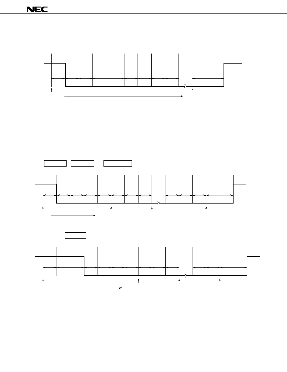
µ
PD17012GF-058
74
(b) Continuous up/down
(i) When AUTO500 switch = 0
<1>
<2>
<3>
40 ms
15 ms
<3>
<5>
40 ms
<3>
<5>
40 ms
<4>
0.5 sec
Key on
Key off
At the band edges, the time of <5> is 500 ms, and the time of <4> is 600 ms to 700 ms.
(ii) When AUTO500 switch = 1
The auto-tuning function is enabled by holding down the key for 0.5 second or more, so that continuous
up/down operation is not performed.
(2) Automatic up/down
(a)
SEEK UP , SCAN UP , or SCAN DWN key
<1>
<2>
<3>
40 ms
15 ms
<5>
<3>
40 ms
<6>
<5>
40 ms
<6>
<5>
40 ms
<6>
<4>
300 - 400 ms
SD, IF check
Station involved
SD, IF check
Station not involved
SD, IF check
Station not involved
Key on
<3>
(b) When the MAN UP key is held down for 0.5 second or more when AUTO500 switch = 1
<2>
0.5 sec
<6>
<5>
40 ms
<3>
<6>
<6>
<5>
40 ms
<3>
<4>
300 - 400 ms
SD, IF check
Station involved
SD, IF check
Station not involved
SD, IF check
Station not involved
Key on
<1>
15 ms
<5>
40 ms
In either case (a) or case (b), the time of <5> is 540 ms at the band edges.
An IF check is made twice in the FAST mode and SLOW mode.

µ
PD17012GF-058
75
(3) Calling a preset memory
<2>
15 ms
<4>
40 ms
<3>
Key on
400 - 500 ms
<1>
Key off
2 seconds
or less
(4) Write to a preset memory
Mute output operation is not performed.
(5) Band switching
15 ms
Key on
<1>
40 ms
<4>
600 - 700 ms
<2>
<3>
(6) Turning on or off the radio set
15 ms
RDSET switch on
<1>
40 ms
<4>
600 - 700 ms
<2>
<3>
(Radio)
(Tape, CD)
(7) Turning on or off the tape or CD
15 ms
<1>
40 ms
<2>
<4>
(Tape, CD)
(Radio, tape, CD)
600 - 700 ms
MUTESEL switch = 0
MUTESEL switch = 1
TPSET switch on
CDSET switch on
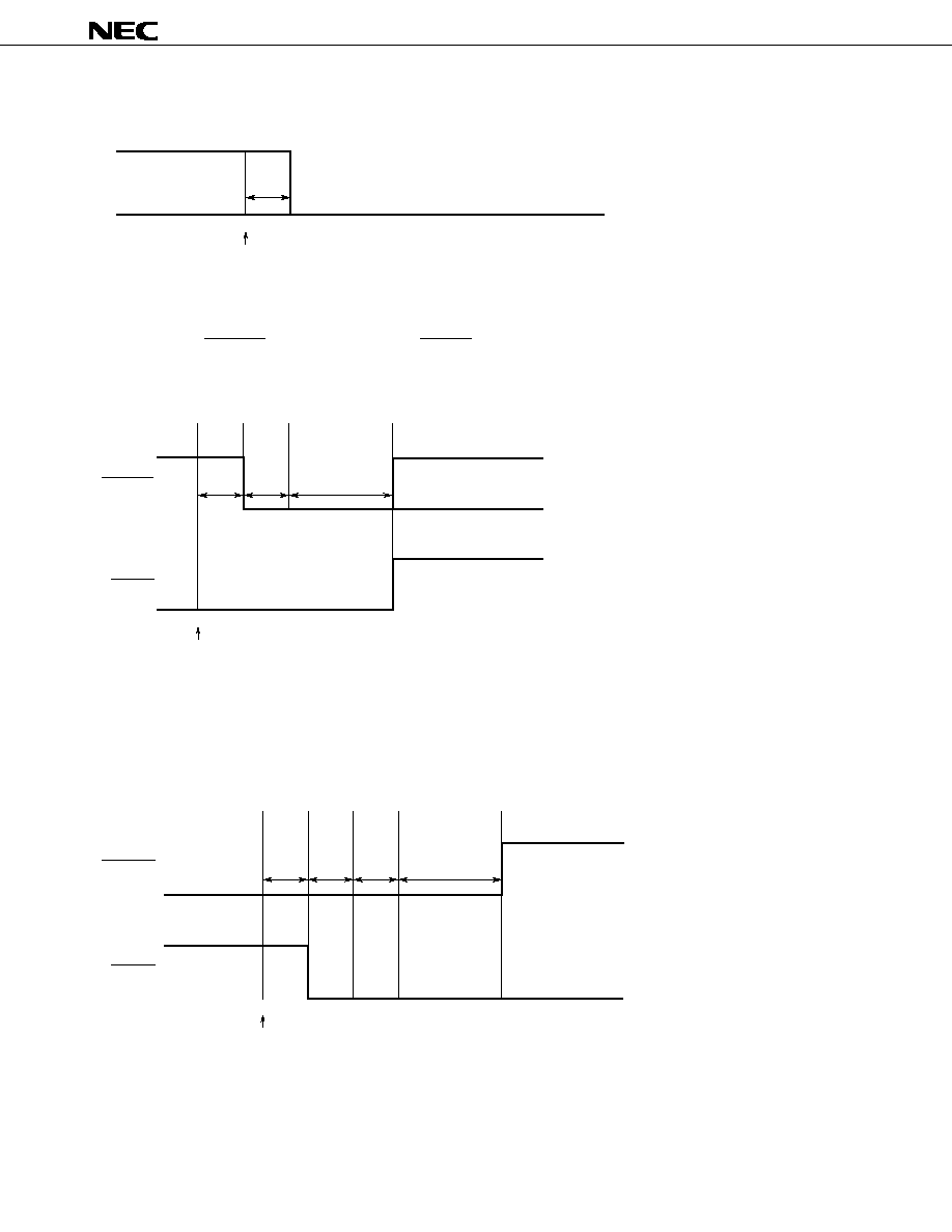
µ
PD17012GF-058
76
(8) Pulling the CE pin from high to low
MAX.
5ms
CE = low
(Radio, tape, CD)
Caution When using alarm mode, always pull up the CE pin.
7.2 Radio Mute (RDMUTE Pin) and Audio Mute (AMUTE Pin) Output Timing Charts
(1) When the mode is switched from radio mode to tape or CD mode
TPSET switch on
CDSET switch on
40 ms
600 - 700 ms
15 ms
<1>
<2>
<4>
RDMUTE
AMUTE
MUTESEL = 1
MUTESEL = 0
(2) When the radio monitor function is used (Set MUTESEL to 0.)
(a) Switching the radio monitor function from off to on
<1>
15 ms
<4>
<3>
<2>
600 - 700 ms
40 ms
RDMUTE
AMUTE
(Tape, CD)
(Radio monitor)
RDMONI key on
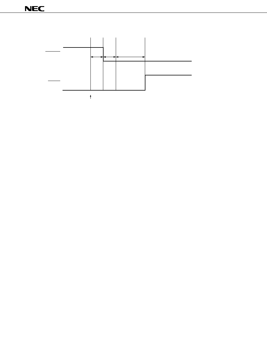
µ
PD17012GF-058
77
(b) Switching the radio monitor function from on to off
<1>
15 ms
<4>
<2>
600 - 700 ms
RDMUTE
AMUTE
(Radio monitor)
(Tape, CD)
RDMONI key on
40 ms
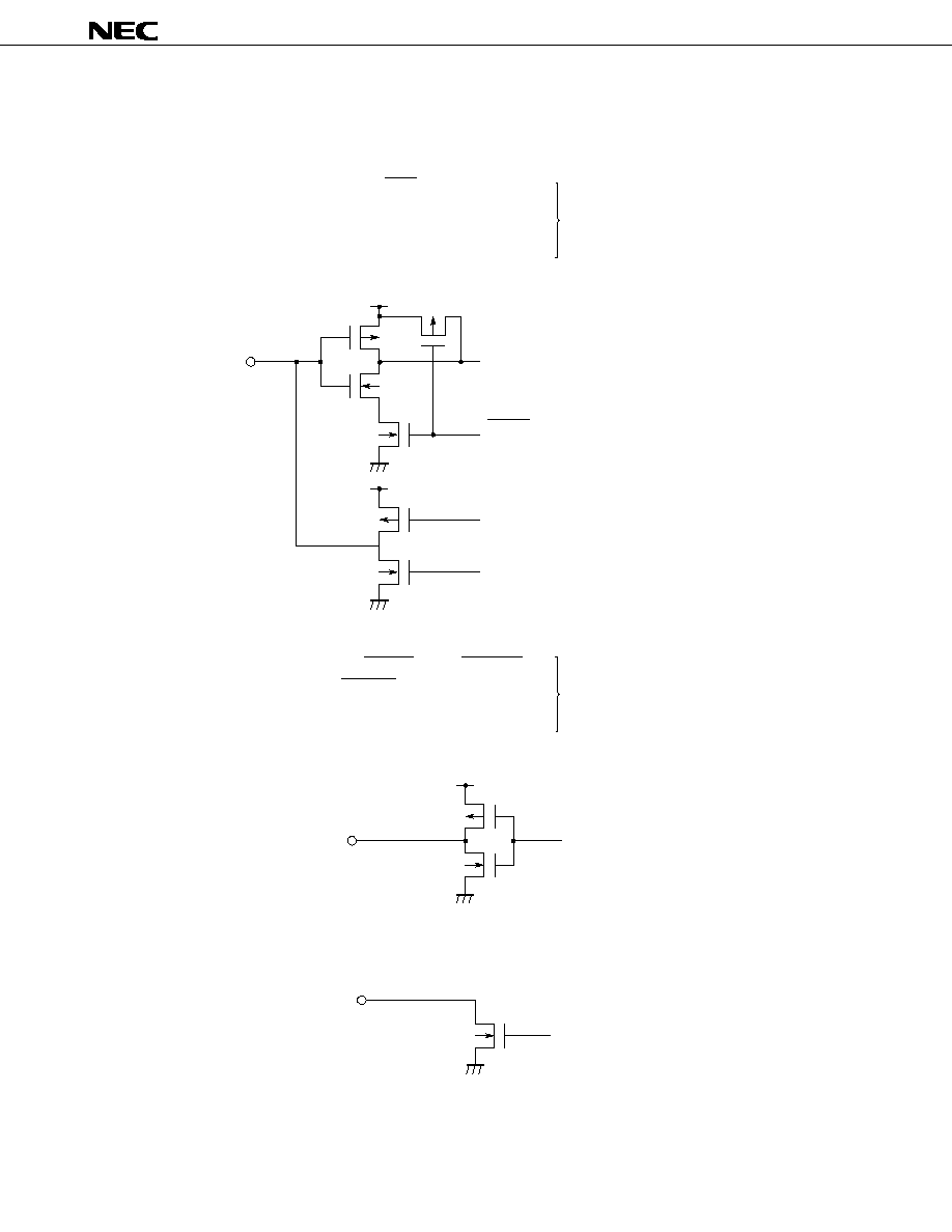
µ
PD17012GF-058
78
8. PIN I/O CIRCUITS
The I/O circuit of each pin of the
µ
PD17012GF-058 is illustrated below in a simplified form.
(1) P0A (P0A0/ALARMIN, P0A1/SO1, P0A2/SCK)
P0B (P0B1/BEEP, P0B0/IGNITION)
P1A (P1A2/MONO, P1A1/EVOL_SCK, P1A0/EVOL_DA)
P1D (P1D3/LOUD, P1D2/POWER, P1D1/BAND1, P1D0/BAND2)
V
DD
RESET (for other than P1D)
Read instruction (for P1D only)
V
DD
(2) P1C (P1C3/AGCC, P1C2/LOC, P1C1/AMUTE, P1C0/RDMUTE)
P2H0/POUT, P2G0/ILLUMI, P2E0/LCD CS
PYA13/MTL, PYA12/CDOUT, PYA11/MODE2, PYA10/MODE1,
PYA9/KS9-PYA0/KS0
V
DD
(3) P0C (P0C3/ALARMOUT, P0C2/KEYS2 - P0C0/KEYS0) (Output)
(I/O)
(Output)
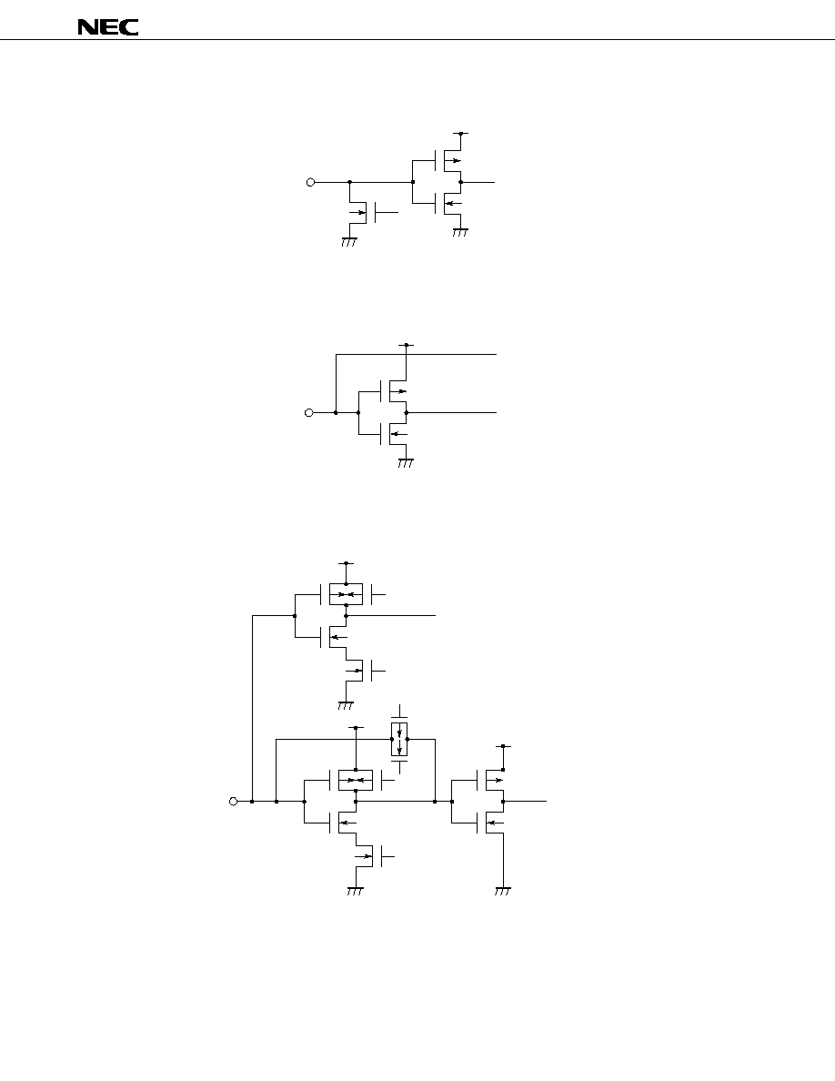
µ
PD17012GF-058
79
(4) P0D (P0D3/K3-P0D0/K0) (Input)
(5) P1B (P1B1/ADC1/KY-IN, P1B0/ADC0/SD) (Input)
V
DD
A/D converter
(6) P1B (P1B3/FMIFC, P1B2/AMIFC) (Input)
V
DD
V
DD
V
DD
General-purpose port
High-on resistance
Frequency counter
V
DD
High-on
resistance
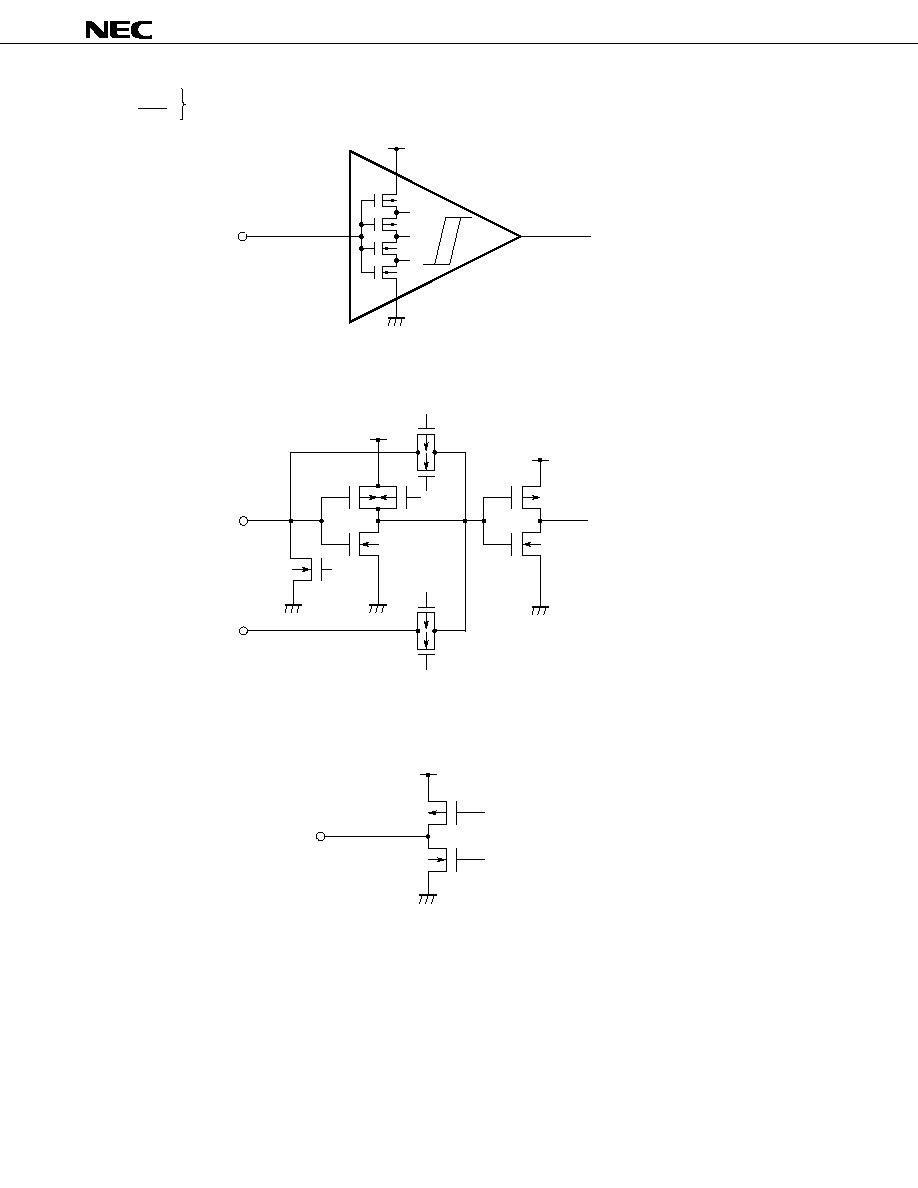
µ
PD17012GF-058
80
(7) CE
INT/REM
V
DD
(8) X
OUT
(Output), X
IN
(Input)
V
DD
V
DD
High-on
resistance
Internal clock
X
IN
X
OUT
High-on
resistance
(9) EO (Output)
V
DD
(Schmitt-triggered input)

µ
PD17012GF-058
81
(10) VCOH
VCOL
(Input)
V
DD
V
DD
High-on
resistance
High-on
resistance

µ
PD17012GF-058
82
9. SAMPLE APPLICATION CIRCUITS
Note
When the
µ
PD7225 external LCD controller/driver is used, connect the C/D pin to the V
DD
pin at the
µ
PD7225.
AM
CH PM
FM 1
FM 2
FM 3
MW LW
To FM,
MW,
VCO
28
CS
12 V
5 V
Piezoelectric buzzer
PD17012GF-058-3BE
µ
1
2
3
4
5
6
7
8
9
10
11
12
13
14
15
16
17
18
19
51
50
49
48
47
46
45
44
43
42
41
40
39
38
37
36
35
34
33
64 63 62 61 60 59 58 57 56 55 54 53 52
20 21 22 23 24 25 26 27 28 29 30 31 32
REM
K
0
K
1
K
2
K
3
GND
KS
0
KS
1
KS
2
KS
3
KS
4
KS
5
MONO
KS6
KS7
KS8
KS9
MODE1
MODE2
CDOUT
MTL
IC
IC
IC
ILLUMI
POUT
IC
IC
IC
BAND2
BAND1
AGCC
LOC
AMUTE
RDMUTE
X
OUT
X
IN
GND
KEYS2
KEYS1
KEYS0
LOUD
POWER
E0
V
DD
1
CE
V
DD
2
SCK
SO
ALARMIN
KY-IN
DSP1
DSP2
BEEP
IGNITION
FMIFC
AMIFC
SD
VCOL
VCOH
PD6121G-001
µ
µ
PC2800HA
Preamplifier for remote control
To the
electronic
volume
LCD
controller/
driver
PD7225
Device for sending
remote-controller signal
Note
DSP
Car ignition
switch
Car door
switch
CLASSIC
NORMAL
ROCK
MONO
MTL
ST
POP
RESET
ALARM
ARMING EXIT
ENTRY
RDMONI
LOUD
ALARMOUT
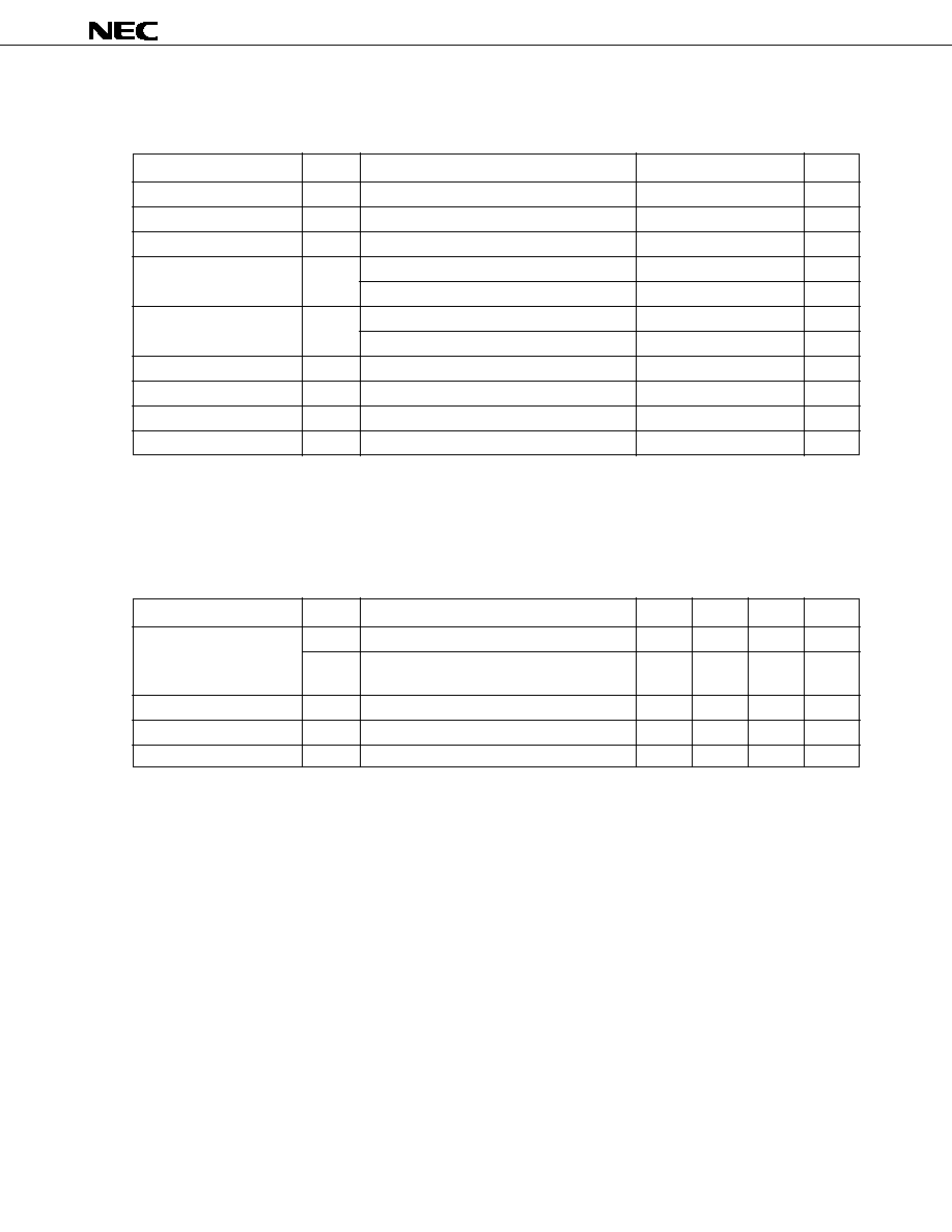
µ
PD17012GF-058
83
10. ELECTRICAL CHARACTERISTICS (PRELIMINARY)
ABSOLUTE MAXIMUM RATINGS (T
A
= 25 ∞C)
Caution Absolute maximum ratings are rated values beyond which physical damage will be caused to the
product; if the rated value of any of the parameters in the above table is exceeded, even
momentarily, the quality of the product may deteriorate. Always use the product within its rated
values.
RECOMMENDED OPERATING RANGES (T
A
= -40 to +85 ∞C)
Supply voltage
Input voltage
Output voltage
Output high current
Output low current
Output withstand voltage
Total loss
Operating ambient temperature
Storage temperature
V
DD
V
I
V
O
I
OH
I
OL
V
BDS
P
t
T
A
T
stg
Except for P0C0 to P0C3
Each pin
Total for all pins
Each pin
Total for all pins
P0C0 - P0C3
V
V
V
mA
mA
mA
mA
V
mW
∞C
∞C
-0.3 to +6.0
-0.3 to V
DD
+ 0.3
-0.3 to V
DD
+ 0.3
-12.0
-20.0
15.0
30.0
14.0
200
-40 to +85
-55 to +125
Parameter
Symbol
Conditions
Rated value
Unit
Supply voltage
Data hold voltage
Output withstand voltage
Rise time of supply voltage
When the entire chip is operating
When the CPU is operating, but the PLL is
not
When the crystal oscillator is stopped
P0C0 - P0C3
V
DD
: 0
4.5 V
V
V
V
V
ms
Parameter
Symbol
Conditions
Unit
4.5
3.5
2.3
MIN.
5.0
5.0
TYP.
5.5
5.5
5.5
12.0
500
MAX.
V
DD1
V
DD2
V
DDR
V
BDS
t
rise
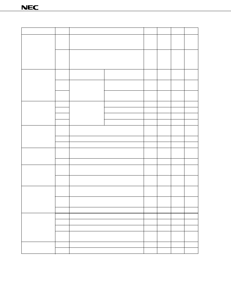
µ
PD17012GF-058
84
DC CHARACTERISTICS (T
A
= -40 to +85 ∞C, V
DD
= 5 V
±
10 %)
Supply current
Data hold voltage
Data hold current
Input high voltage
Input low voltage
Output high current
Output low current
Input high current
Output-off leakage
current
Parameter
Symbol
Conditions
I
DD1
I
DD2
V
DDR1
V
DDR2
V
DDR3
I
DDR1
I
DDR2
I
DDR3
I
DDR4
V
IH1
V
IH2
V
IH3
V
IL1
V
IL2
I
OH1
I
OH2
I
OL1
I
OL2
I
OL3
I
IH1
I
IH2
I
IH3
I
IH4
I
L1
I
L2
When the crystal os-
cillator is operating
When the crystal os-
cillator is stopped
When the crystal os-
cillator is stopped
With timer FF for interrup-
tion detection
With timer FF for interrup-
tion detection
For holding data
memory
V
DD
= 5 V, T
A
= 25 ∞C
V
DD
= 2.3 V, T
A
= 25 ∞C
V
DD
= 2.3 V
mA
mA
V
V
V
µ
A
µ
A
µ
A
µ
A
V
V
V
V
V
mA
mA
mA
mA
mA
mA
mA
mA
µ
A
µ
A
µ
A
Unit
3.5
2.3
2.0
0.7V
DD
0.8V
DD
0.6V
DD
-1.0
-1.0
1.0
1.0
10
0.1
0.1
0.1
10
MIN.
1.0
0.5
2.0
2.0
1.0
1.0
TYP.
2.0
1.0
4.0
20.0
2.0
10.0
V
DD
V
DD
V
DD
0.2V
DD
0.2V
DD
150
1.0
±
1.0
MAX.
When the CPU is operating but the PLL is not, with a
sinusoidal wave applied to the X
IN
pin (f
IN
= 4.5 MHz,
V
IN
= V
DD
)
When the CPU is operating but the PLL is not, with a
sinusoidal wave applied to the X
IN
pin (f
IN
= 4.5 MHz,
V
IN
= V
DD
)
When the HALT instruction is issued
P0A1, P0B0 - P0B3, P1A0 - P1A2, P1B0 - P1B3,
P1D0 - P1D3
P0A0, P0A2, CE, INT
P0D0 - P0D3
P0A1, P0B0 - P0B3, P0D0 - P0D3, P1A0 - P1A2,
P1B0 - P1B3, P1D0 - P1D3
P0A0, P0A2, CE, INT
P0A0 - P0A2, P0B0 - P0B3, P1A0 - P1A2,
P1C0 - P1C3, P1D0 - P1D3
PYA0 - PYA9, PYA11
-
PYA15, P2E0, P2F0, P2G0,
P2H0, EO
P0A0 - P0A2, P0B0 - P0B3, P1A0 - P1A2,
P1C0 - P1C3, P1D0 - P1D3
PYA0 - PYA9, PYA11
-
PYA15, P2E0, P2F0, P2G0,
P2H0, EO
P0C0 - P0C3
When the VCOH pin is pulled down
When the VCOL pin is pulled down
When the X
IN
pin is pulled down
When the P0D0 to P0D3 pins are
pulled down
P0C0 - P0C3
EO
V
OH
= V
DD
- 1 V
V
OH
= V
DD
- 1 V
V
OL
= 1 V
V
OL
= 1 V
V
OL
= 1 V
V
IH
= V
DD
V
IH
= V
DD
V
IH
= V
DD
V
IH
= V
DD
V
OH
= 12 V
V
OH
= V
DD
, V
OL
= 0 V
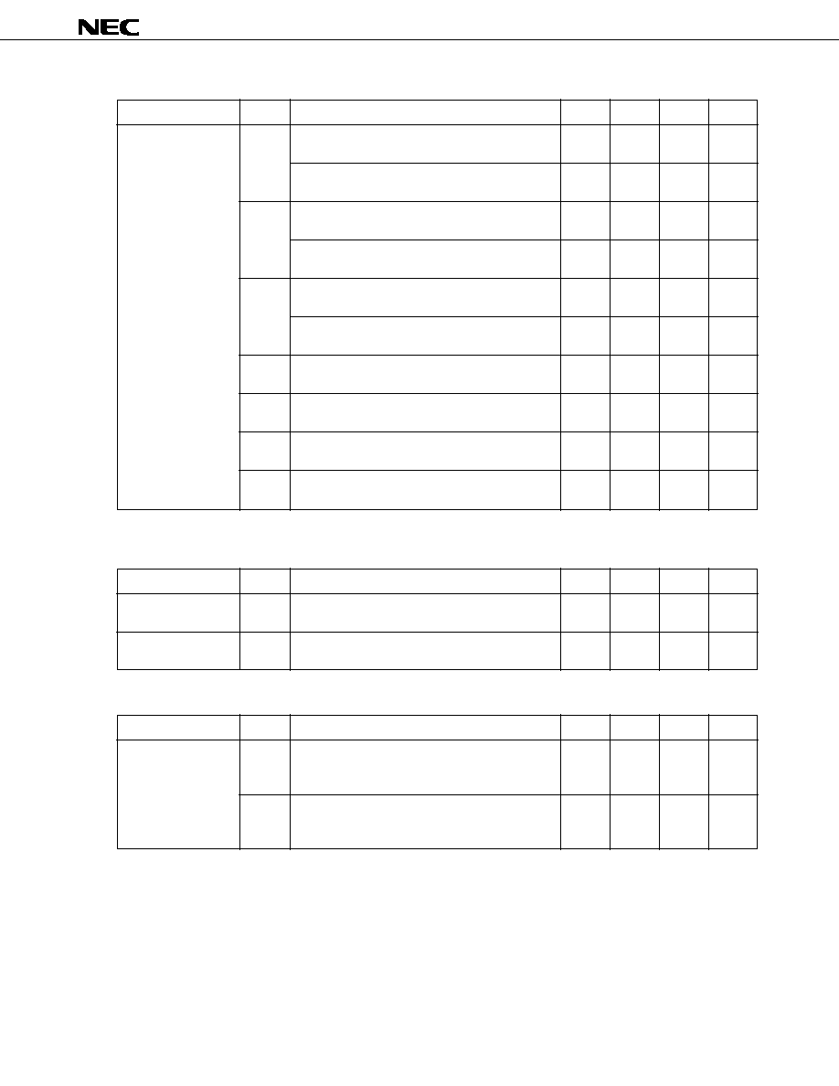
µ
PD17012GF-058
85
AC CHARACTERISTICS (T
A
= -40 to +85 ∞C, V
DD
= 5 V
±
10 %)
A/D CONVERTER CHARACTERISTICS (T
A
= -40 to +85 ∞C, V
DD
= 5 V
±
10 %)
OTHER CHARACTERISTICS (T
A
= +25 ∞C, V
DD
= 5.0 V, for reference purposes only)
Operating frequency
Parameter
VCOL pin in MF mode, with a sinusoidal wave applied
at V
IN
= 0.15 V
p-p
VCOL pin in MF mode, with a sinusoidal wave applied
at V
IN
= 0.3 V
p-p
VCOL pin in HF mode, with a sinusoidal wave applied
at V
IN
= 0.15 V
p-p
VCOL pin in HF mode, with a sinusoidal wave applied
at V
IN
= 0.3 V
p-p
VCOH pin in VHF mode, with a sinusoidal wave
applied at V
IN
= 0.15 V
p-p
VCOH pin in VHF mode, with a sinusoidal wave
applied at V
IN
= 0.3 V
p-p
AMIFC FMIFC pin in AMIF count mode, with a sinu-
soidal wave applied at V
IN
= 0.3 V
p-p
AMIFC pin in AMIF count mode, with a sinusoidal
wave applied at V
IN
= 0.1 V
p-p
FMIFC pin in FMIF count mode, with a sinusoidal
wave applied at V
IN
= 0.3 V
p-p
FMIFC pin in FMIF count mode, with a sinusoidal
wave applied at V
IN
= 0.1 V
p-p
Symbol
Conditions
f
IN1
f
IN2
f
IN3
f
IN4
f
IN5
f
IN6
f
IN7
MHz
MHz
MHz
MHz
MHz
MHz
MHz
MHz
MHz
MHz
Unit
0.90
0.50
5
5
60
30
0.3
0.44
5
10.5
MIN.
TYP.
30
20
25
40
130
250
1.0
0.46
15
10.9
MAX.
Resolution of A/D
conversion
Total error in A/D
conversion
Parameter
T
A
= -10 to +50 ∞C
Symbol
Conditions
bit
LSB
Unit
MIN.
TYP.
6
±
1.5
MAX.
±
1.0
Supply current
Parameter
When the CPU and PLL are operating, with a
sinusoidal wave applied to the VCOH pin
(f
IN
= 130 MHz, V
IN
= 0.3 V
p-p
)
When the CPU and PLL are operating, with a
sinusoidal wave applied to the VCOH pin
(f
IN
= 250 MHz, V
IN
= 0.3 V
p-p
)
Symbol
Conditions
mA
mA
Unit
MIN.
TYP.
MAX.
12
13
I
DD3
I
DD4

µ
PD17012GF-058
86
11. PACKAGE DRAWING
64 PIN PLASTIC QFP (14 20)
ITEM
MILLIMETERS
INCHES
G
Q
F
1.0
0.125
±
0.075
1.0
S
0.039
0.005
±
0.003
0.039
S64GF-100-3B8, 3BE-3
NOTE
Each lead centerline is located within 0.20 mm (0.008 inch) of
its true position (T.P.) at maximum material condition.
3.0 MAX.
0.119 MAX.
D
17.2
±
0.2
0.677
±
0.008
R
5
∞±
5
∞
5
∞±
5
∞
B
20.0
±
0.2
0.787 +0.009
≠0.008
A
23.2
±
0.2
0.913+0.009
≠0.008
C
14.0
±
0.2
0.551 +0.009
≠0.008
J
1.0 (T.P.)
0.039 (T.P.)
I
0.20
0.008
H
0.40
±
0.10
0.016 +0.004
≠0.005
P
2.7
0.106
N
0.10
0.004
L
0.8
±
0.2
0.031 +0.009
≠0.008
M
0.15
0.006 +0.004
≠0.003
K
1.6
±
0.2
0.063
±
0.008
+0.10
≠0.05
detail of lead end
I
J
F
G
H
Q
R
P
K
M
L
N
M
51
52
32
64
1
20
19
33
A
B
C D
S

µ
PD17012GF-058
87
12. RECOMMENDED SOLDERING CONDITIONS
The conditions listed below shall be met when soldering the
µ
PD17012GF-058.
For details of the recommended soldering conditions, refer to our document
SMD Surface Mount Technology
Manual (C10535E).
Please consult with our sales offices in case any other soldering process is used, or in case soldering is done under
different conditions.
Table 12-1. Soldering Conditions for Surface-Mount Devices
µ
PD17012GF-058-3BE: 64-pin plastic QFP (14
◊
20 mm, 0.1 mm pitch)
Note
Exposure limit before soldering after dry-pack package is opened.
Storage conditions: Temperature of 25 ∞C and maximum relative humidity at 65 % or less
Caution Do not apply more than a single process at once, except for "Partial heating method."
Soldering conditions
Peak package's surface temperature: 235 ∞C
Reflow time: 30 seconds or less (at 210 ∞C or more)
Maximum allowable number of reflow processes: 2
Exposure limit
Note
: 7 days (20 hours of pre-baking is required at
125 ∞C afterward.)
<Cautions>
Non-heat-resistant trays, such as magazine and taping trays, cannot be
backed before unpacking.
Peak package's surface temperature: 215 ∞C
Reflow time: 40 seconds or less (at 200 ∞C or more)
Maximum allowable number of reflow processes: 2
Exposure limit
Note
: 7 days (20 hours of pre-baking is required at
125 ∞C afterward.)
<Cautions>
Non-heat-resistant trays, such as magazine and taping trays, cannot be
backed before unpacking.
Temperature in the soldering vessel: 260 ∞C or less
Soldering time: 10 seconds or less
Number of soldering processes: 1
Pre-heating temperature: 120 ∞C max.
(package surface temperature)
Exposure limit
Note
: 7 days
(20 hours of pre-baking is required at 125 ∞C afterward.)
<Cautions>
Non-heat-resistant trays, such as magazine and taping trays, cannot be
backed before unpacking.
Terminal temperature: 300 ∞C or less
Flow time: 3 seconds or less (for each side of device)
Symbol
IR35-207-2
VP15-207-2
WS60-207-1
-
Soldering process
Infrared ray reflow
VPS
Wave soldering
Partial heating method
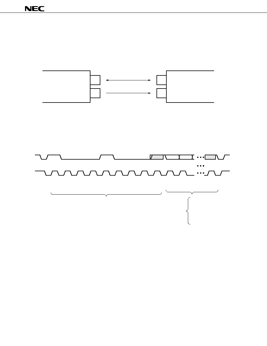
µ
PD17012GF-058
88
APPENDIX COMMUNICATION WITH ELECTRONIC VOLUME CONTROL IC (I
2
C BUS INTERFACE)
The
µ
PD17012-058 sends specified data, such as volume and balance data, to the electronic volume control IC.
Two buses, the data bus and clock bus, are necessary to output data to the electronic volume control IC. Data and
clock signals are output from the EVOL_DA pin (pin 2) and EVOL_SCK pin (pin 1) of the
µ
PD17012-058.
Figure A-1. Pin Connections (Electronic Volume Control)
Electronic volume control data consists of nine bits (eight bits for data and a check bit). The electronic volume
address (nine bits) and control data (nine bits) are sequentially transferred N times, where N is the number of
transferred data items, such as the volume and balance data.
Figure A-2. Data Transfer Format (Electronic Volume Control)
PD17012GF-058
µ
EVOL_DA
EVOL_SCK
2
1
SDA
SCL
27
28
Data
Clock
Electronic volume
control IC
1
2
3
4
5
6
7
8
9
1
2
9
1
0
0
0
1
0
0
0
Volume
Balance
Audio switch
Bass
Treble
Fader
Electronic volume address
Data for
SDA
SCL

µ
PD17012GF-058
89
[MEMO]
µ
PD17012GF-058
90
NOTES FOR CMOS DEVICES
1
PRECAUTION AGAINST ESD FOR SEMICONDUCTORS
Note: Strong electric field, when exposed to a MOS device, can cause destruction
of the gate oxide and ultimately degrade the device operation. Steps must
be taken to stop generation of static electricity as much as possible, and
quickly dissipate it once, when it has occurred. Environmental control must
be adequate. When it is dry, humidifier should be used. It is recommended
to avoid using insulators that easily build static electricity. Semiconductor
devices must be stored and transported in an anti-static container, static
shielding bag or conductive material. All test and measurement tools
including work bench and floor should be grounded. The operator should
be grounded using wrist strap. Semiconductor devices must not be touched
with bare hands. Similar precautions need to be taken for PW boards with
semiconductor devices on it.
2
HANDLING OF UNUSED INPUT PINS FOR CMOS
Note: No connection for CMOS device inputs can be cause of malfunction. If no
connection is provided to the input pins, it is possible that an internal input
level may be generated due to noise, etc., hence causing malfunction. CMOS
device behave differently than Bipolar or NMOS devices. Input levels of
CMOS devices must be fixed high or low by using a pull-up or pull-down
circuitry. Each unused pin should be connected to V
DD
or GND with a
resistor, if it is considered to have a possibility of being an output pin. All
handling related to the unused pins must be judged device by device and
related specifications governing the devices.
3
STATUS BEFORE INITIALIZATION OF MOS DEVICES
Note: Power-on does not necessarily define initial status of MOS device. Produc-
tion process of MOS does not define the initial operation status of the device.
Immediately after the power source is turned ON, the devices with reset
function have not yet been initialized. Hence, power-on does not guarantee
out-pin levels, I/O settings or contents of registers. Device is not initialized
until the reset signal is received. Reset operation must be executed imme-
diately after power-on for devices having reset function.

µ
PD17012GF-058
91
NEC Electronics Inc. (U.S.)
Santa Clara, California
Tel: 800-366-9782
Fax: 800-729-9288
NEC Electronics (Germany) GmbH
Duesseldorf, Germany
Tel: 0211-65 03 02
Fax: 0211-65 03 490
NEC Electronics (UK) Ltd.
Milton Keynes, UK
Tel: 01908-691-133
Fax: 01908-670-290
NEC Electronics Italiana s.r.1.
Milano, Italy
Tel: 02-66 75 41
Fax: 02-66 75 42 99
NEC Electronics Hong Kong Ltd.
Hong Kong
Tel: 2886-9318
Fax: 2886-9022/9044
NEC Electronics Hong Kong Ltd.
Seoul Branch
Seoul, Korea
Tel: 02-528-0303
Fax: 02-528-4411
NEC Electronics Singapore Pte. Ltd.
United Square, Singapore 1130
Tel: 253-8311
Fax: 250-3583
NEC Electronics Taiwan Ltd.
Taipei, Taiwan
Tel: 02-719-2377
Fax: 02-719-5951
NEC do Brasil S.A.
Sao Paulo-SP, Brasil
Tel: 011-889-1680
Fax: 011-889-1689
NEC Electronics (Germany) GmbH
Benelux Office
Eindhoven, The Netherlands
Tel: 040-2445845
Fax: 040-2444580
NEC Electronics (France) S.A.
Velizy-Villacoublay, France
Tel: 01-30-67 58 00
Fax: 01-30-67 58 99
NEC Electronics (France) S.A.
Spain Office
Madrid, Spain
Tel: 01-504-2787
Fax: 01-504-2860
NEC Electronics (Germany) GmbH
Scandinavia Office
Taeby, Sweden
Tel: 08-63 80 820
Fax: 08-63 80 388
Regional Information
Some information contained in this document may vary from country to country. Before using any NEC
product in your application, please contact the NEC office in your country to obtain a list of authorized
representatives and distributors. They will verify:
∑ Device availability
∑ Ordering information
∑ Product release schedule
∑ Availability of related technical literature
∑ Development environment specifications (for example, specifications for third-party tools and
components, host computers, power plugs, AC supply voltages, and so forth)
∑ Network requirements
In addition, trademarks, registered trademarks, export restrictions, and other legal issues may also vary
from country to country.
J96. 8

µ
PD17012GF-058
No part of this document may be copied or reproduced in any form or by any means without the prior written
consent of NEC Corporation. NEC Corporation assumes no responsibility for any errors which may appear in this
document.
NEC Corporation does not assume any liability for infringement of patents, copyrights or other intellectual
property rights of third parties by or arising from use of a device described herein or any other liability arising
from use of such device. No license, either express, implied or otherwise, is granted under any patents,
copyrights or other intellectual property rights of NEC Corporation or others.
While NEC Corporation has been making continuous effort to enhance the reliability of its semiconductor devices,
the possibility of defects cannot be eliminated entirely. To minimize risks of damage or injury to persons or
property arising from a defect in an NEC semiconductor device, customers must incorporate sufficient safety
measures in its design, such as redundancy, fire-containment, and anti-failure features.
NEC devices are classified into the following three quality grades:
"Standard", "Special", and "Specific". The Specific quality grade applies only to devices developed based on
a customer designated "quality assurance program" for a specific application. The recommended applications
of a device depend on its quality grade, as indicated below. Customers must check the quality grade of each
device before using it in a particular application.
Standard: Computers, office equipment, communications equipment, test and measurement equipment,
audio and visual equipment, home electronic appliances, machine tools, personal electronic
equipment and industrial robots
Special: Transportation equipment (automobiles, trains, ships, etc.), traffic control systems, anti-disaster
systems, anti-crime systems, safety equipment and medical equipment (not specifically designed
for life support)
Specific: Aircrafts, aerospace equipment, submersible repeaters, nuclear reactor control systems, life
support systems or medical equipment for life support, etc.
The quality grade of NEC devices is "Standard" unless otherwise specified in NEC's Data Sheets or Data Books.
If customers intend to use NEC devices for applications other than those specified for Standard quality grade,
they should contact an NEC sales representative in advance.
Anti-radioactive design is not implemented in this product.
M4 96. 5
The application circuits and their parameters are for reference only and are not intended for use in actual design-ins.
Caution This product contains an I
2
C bus interface circuit.
When using the I
2
C bus interface, notify its use to NEC when ordering custom code. NEC can
guarantee the following only when the customer informs NEC of the use of the interface:
Purchase of NEC I
2
C components conveys a license under the Philips I
2
C Patent Rights to use these
components in an I
2
C system, provided that the system conforms to the I
2
C Standard Specification
as defined by Philips.