Document Outline
- COVER
- FEATURES
- ORDERING INFORMATION
- PIN CONFIGURATION (Top View)
- PIN IDENTIFICATIONS
- BLOCK DIAGRAM
- DIFFERENCES BETWEEN PRODUCTS
- 1. PIN FUNCTIONS
- 2. NEC TRANSMISSION FORMAT (REM OUTPUT)
- 3. CUSTOM CODE (CUSTOM CODE, CUSTOM CODEê) SETTING
- 3.1 Standard versions with Ver I specs. (mPD6121-001, mPD6122-001)
- 3.2 Standard versions with Ver II specs. (mPD6121-002, 6122-002)
- 4. REMOTE OUTPUT WAVEFORM (NEC TRANSMISSION FORMAT:
ONE-SHOT COMMAND TRANSMISSION MODE)
- 5. KEY DATA CODES (SINGLE INPUT)
- 6. DOUBLE-INPUT OPERATION
- 7. ONE-SHOT/CONTINUOUS COMMAND TRANSMISSION MODE
- 7.1 One-shot Command Transmission Mode
- 7.2 Continuous Command Transmission Mode
- 8. APPLICATION CIRCUIT EXAMPLE
- 9. ELECTRICAL SPECIFICATIONS
- 10. PACKAGE DRAWINGS
- 11. RECOMMENDED SOLDERING CONDITIONS
- APPENDIX. REMOTE CONTROL TRANSMISSION IC AND MICROCONTROLLER LIST

©
1994
DATA SHEET
MOS INTEGRATED CIRCUIT
The
µ
PD6121, 6122 are infrared remote control transmission ICs using the NEC transmission format that are ideally
suited for TVs, VCRs, audio equipment, air conditioners, etc. By combining external diodes and resistors, a maximum
of 65,536 custom codes can be specified. These ICs come in small packages, thus facilitating the design of light
and compact remote control transmitters.
The NEC transmission format consists of leader codes, custom codes (16 bits), and data codes (16 bits). It can
be used for various systems through decoding by a microcontroller.
FEATURES
∑
Low-voltage operation: V
DD
= 2.0 to 3.3 V
∑
Low current dissipation: 1
µ
A Max. (at standby)
∑
Custom codes: 65,536 (set by external diodes and resistors)
∑
Data codes:
∑
µ
PD6121: 32 codes (single input), 3 codes (double input), expandable up to 64 codes through SEL pin
∑
µ
PD6122: 64 codes (single input), 3 codes (double input), expandable up to 128 codes through SEL pin
∑
µ
PD6121, 6122 are transmission code-compatible (NEC transmission format) with the
µ
PD1913C
Note
, 1943G
Note
,
6102G
Note
, and 6120C
Note
.
∑
Pin compatibility:
∑
µ
PD6121G-001 is pin-compatible with the
µ
PD1943G (However, capacitance of capacitor connected to
oscillator pin and other parameters vary)
∑
µ
PD6122G-001 is pin-compatible with the
µ
PD6102G (However, capacitance of capacitor connected to
oscillator pin and other parameters vary)
∑
Standard products (Ver. I, Ver. II specifications)
Note Provided for maintenance purpose only
∑ When using this product (in NEC transmission format), please order custom codes from NEC.
∑ New custom codes for the
µ
PD6121G-002,
µ
PD6122G-002 cannot be ordered.
µ
PD6121, 6122
The information in this document is subject to change without notice.
The mark shows revised points.
Document No. U10114EJ6V0DS00 (6th edition)
(Previous No. IC-1813)
Date Published October 1995 P)
Printed in Japan
REMOTE CONTROL TRANSMISSION CMOS IC
*
*
*
*
DATA SHEET
©
1994
µ
PD6121, 6122
2
ORDERING INFORMATION
Part number
Package
Description
µ
PD6121G-001
20-pin plastic SOP (375 mil)
Standard (Ver I spec.)
µ
PD6121G-002
20-pin plastic SOP (375 mil)
Standard (Ver II spec.)
µ
PD6122G-001
24-pin plastic SOP (375 mil)
Standard (Ver I spec.)
µ
PD6122G-002
24-pin plastic SOP (375 mil)
Standard (Ver II spec.)
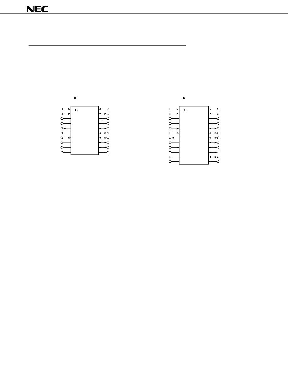
PIN CONFIGURATION (Top View)
PIN IDENTIFICATIONS
CCS
:
Custom code selection input
REM :
Remote output
KI
0
- KI
7
:
Key input
SEL :
SEL input
KI/O
0
- KI/O
7
:
Key input/output
V
DD
:
Power supply pin
LMP
:
Lamp output
V
SS
:
GND pin
OSCI, OSCO:
Resonator connection pin
*
1
2
3
4
5
6
7
8
9
10
20
19
18
17
16
15
14
13
12
11
KI
0
KI
1
KI
2
KI
3
REM
V
DD
SEL
OSCO
OSCI
V
SS
CCS
KI/O
0
KI/O
1
KI/O
2
KI/O
3
KI/O
4
KI/O
5
KI/O
6
KI/O
7
LMP
µPD6121
µPD6121G-001
µPD6121G-002
µPD6122
1
2
3
4
5
6
7
8
9
10
24
23
22
21
20
19
18
17
16
15
KI
2
KI
3
KI
4
KI
5
KI
6
KI
7
REM
V
DD
SEL
OSCO
KI
1
KI
0
CCS
KI/O
0
KI/O
1
KI/O
2
KI/O
3
KI/O
4
KI/O
5
KI/O
6
µPD6122G-001
µPD6122G-002
11
14
OSCI
12
13
V
SS
LMP
KI/O
7
µ
PD6121, 6122
3
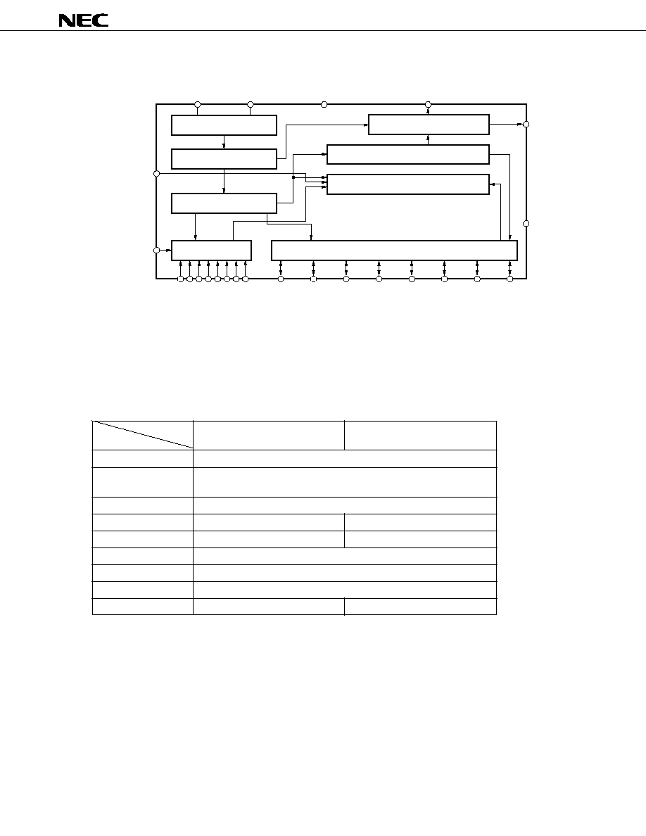
BLOCK DIAGRAM
Note
µ
PD6121: KI
0
- KI
3
µ
PD6122: KI
0
- KI
7
DIFFERENCES BETWEEN PRODUCTS
Part number
µ
PD6121
µ
PD6122
Item
Operating voltage
V
DD
= 2.0 to 3.3 V
Current consumption
1
µ
A MAX.
(at standby)
Custom codes
65,536 (16-bit setting)
Data codes
32 x 2
64 x 2
No. of KI pins
4
8
No. of KI/O pins
8
SEL pin
Provided
Transmission format
NEC transmission format
Package
20-pin plastic SOP (375 mil)
24-pin plastic SOP (375 mil)
*
OSCO
OSCI
V
DD
LMP
REM
V
SS
KI/O
7
KI/O
6
KI/O
5
KI/O
4
KI/O
3
KI/O
2
KI/O
1
KI/O
0
KI
0
≠ KI
n
Note
Key input circuit
Timing generator
Frequency divider
Oscillator
Output circuit
Controller
Data register
Key input/output circuit
SEL
CCS

µ
PD6121, 6122
4
1. PIN FUNCTIONS
(1) Key input pins (KI
0
to KI
7
), key input/output pins (KI/O
0
to KI/O
7
)
A pull-down resistor is placed between key input pins and a V
SS
pin. When several keys are pressed
simultaneously, the transmission of the corresponding signals is inhibited by a multiple-input prevention circuit.
In the case of double-key input, transmission is inhibited if both keys are pressed simultaneously (within 36 ms
interval); if not pressed simultaneously, the priority of transmission is first key, then second key.
When a key is pressed, the custom code and data code reading is initiated, and 36 ms later, output to REM output
is initiated. Thus if the key is pressed during the initial 36 ms, one transmission is performed. If a key is kept
pressed for 108 ms or longer, only leader codes are consecutively transmitted until the key is released.
Keys can be operated intermittently at intervals as short as 126 ms (interval between two on's), making this an
extremely fast-response system.
(
2) Resonator connection pins (OSCI, OSCO)
The oscillator starts operating when it receives a key input. Use a ceramic resonator with a frequency between
400 and 500 kHz.
(3) Power-supply pin
The power supply voltage is supplied by two 3-V batteries. A broad range of operating power supply voltage is
allowed, from 2.0 to 3.3 V. The supply current falls below 1
µ
A when the oscillator is inactive when no keys are
pressed.
(4) REM output pin
The REM output pin outputs the transmission code, which consists of the leader code, custom code (16 bits),
and data code (16 bits) (Refer to 2. NEC TRANSMISSION FORMAT (REM OUTPUT)).
(5) SEL input pin
By controlling D
7
of the data code with this pin, the
µ
PD6121 and
µ
PD6122 can transmit 64 and 128 different
data codes, respectively. By connecting the SEL pin to V
DD
or V
SS
, D
7
is set to "0" or "1", respectively.
This pin has high-impedance input, therefore be sure to connect it either to V
DD
or V
SS
.
(6) CCS input pin
By placing a diode between the CCS pin and the KI/O pin, it is possible to set a custom code. When a diode
is connected, the corresponding custom code is "1", and when not connected, it is "0".
(7) LMP output pin
The LMP pin outputs a low-level signal while the REM pin outputs a transmission code.

µ
PD6121, 6122
5
2. NEC TRANSMISSION FORMAT (REM OUTPUT)
The NEC transmission format consists of the transmission of a leader code, 16-bit custom codes (Custom
Code, Custom Code'), and 16-bit data codes (Data Code, Data Code) at one time, as shown in Figure 2-1.
Also refer to 4. REMOTE OUTPUT WAVEFORM.
Data Code is the inverted code of Data Code.
The leader code consists of a 9-ms carrier waveform and a 4.5-ms OFF waveform and is used as leader for
the ensuing code to facilitate reception detection.
Codes use the PPM (Pulse Position Modulation) method, and the signals "1" and "0" are fixed by the interval
between pulses.
Figure 2-1. REM Output Code
Cautions 1. Use any of the possible 256 kinds of custom codes specified with 00xxH (diode not
connected), as desired. If intending to use custom codes other than 00xxH, please consult
NEC in order to avoid various types of errors from occurring between systems.
2. When receiving data in the NEC transmission format, check that the 32 bits made up of the
16-bit custom code (Custom Code, Custom Code') and the 16-bit data code (Data Code, Data
Code) are fully decoded, and that there are no signals with the 33rd bit and after (be sure
to check also Data Code).
C
0
C
1
C
2
C
3
C
4
C
5
C
6
C
7
C
0
' C
1
' C
2
' C
3
' C
4
' C
5
' C
6
' C
7
' D
0
D
1
D
2
D
3
D
4
D
5
D
6
D
7
D
0
D
1
D
2
D
3
D
4
D
5
D
6
D
7
C
0
C
1
C
2
C
3
C
4
C
5
C
6
C
7
or
C
0
or or or or or or or
C
1
C
2
C
3
C
4
C
5
C
6
C
7
=
=
=
=
=
=
=
=
Custom Code
Custom Code'
Data Code
Data Code
Leader Code