Document Outline
- COVER
- FEATURES
- RECOMMENDED USES
- ORDERING INFORMATION
- BLOCK DIAGRAM
- PIN CONFIGURATION (Top View)
- PIN FUNCTIONS
- 1. DESCRIPTION OF OPERATIONS
- 1.1 Analog Input Block
- 1.2 Analog Output Block
- 1.3 Digital Interface
- 1.4 Volume Setting Register Addresses
- 1.5 Volume Setting Register Data (Command Types)
- 1.6 Test Mode
- 2. SYSTEM CONNECTIONS
- 2.1 Analog Input Block
- 2.2 Mic Amp
- 2.3 Analog Output Block
- 2.4 Use Cautions
- 3. ELECTRICAL SPECIFICATIONS
- 4. APPLICATION CIRCUIT EXAMPLE
- 5. RECOMMENDED LAYOUT PATTERN
- 6. PACKAGE DRAWING
- 7. RECOMMENDED SOLDERING CONDITIONS

©
1996
DATA SHEET
MOS INTEGRATED CIRCUIT
µ
PD63310
STEREO SOUND CODEC
The information in this document is subject to change without notice.
The mark shows major revised points.
The
µ
PD63310 is an LSI that features two channels each of on-chip 16-bit ADC and DAC circuits for mutual conversion
between digital signals and audio signals (having a maximum signal bandwidth of 24 kHz).
The analog signal input block enables mixed input of four different stereo signals and one monaural signal, and the
volume of each signal can be controlled before mixing. The
µ
PD63310 also features two on-chip microphone amplifiers
(mic amps) and gain is adjustable between 10 and 30 dB.
The analog signal output block enables mixed output of analog signals output by the DAC and four different stereo
analog signals, and the volume of each signal can be controlled before mixing.
The digital audio signal I/O block supports a serial interface for audio applications (two's complement, MSB first).
A 6-bit parallel port are used for the various volume settings, with volume settings selectable (in 1.5-dB steps) from ≠
46.5 dB to 0 dB, as well as a mute setting.
FEATURES
∑ Two channels each of
type ADC and DAC
∑ On-chip mixing circuit in analog I/O block
∑ Low-noise mic amps for two channels on chip
∑ On-chip reference voltage power supply (1.4 V TYP.)
∑ ADC and DAC digital filter characteristics
Pass band ripple
:
±
0.1 dB (0 to 0.454 fs) for ADC and DAC
Stop band attenuation : 75 dB (0.546 fs or above) for ADC and DAC
∑ Sampling frequency (fs): 2 to 48 kHz (256-fs master clock is input from an external source)
∑ Low voltage operation: +3 to +5.5 V single power supply
∑ Wide operating ambient temperature: ≠20 to +80
∞
C
∑ Low power consumption: 120 mW (when using 3-V power supply), 250 mW (when using 5-V power supply)
∑ 80-pin plastic TQFP
RECOMMENDED USES
∑ Speech recognition system, including car navigation system
∑ PC sound system
ORDERING INFORMATION
Part Number
Package
µ
PD63310GK-9EU
80-pin plastic TQFP (FINE PITCH) (12
◊
12 mm)
Document No. S11319EJ7V0DS00 (7th edition)
Date Published October 1998 N CP(K)
Printed in Japan

µ
PD63310
2
BLOCK DIAGRAM
CSB
SELR
SO
SI
BCLK
LRCLK
RB, WB
MCLK
DATA5-
DATA0
OEB, RBW
2
6
2
I/O interface
Digital I/O terminals
Digital filter
Interpolator
Interpolator
Decimeter
Decimeter
Analog loopback
(for test mode selection)
DAC
DAC
ADC
ADC
Filter
Filter
Mixer
Mixer
MIC AMP
MIC AMP
≠
+
≠
+
Mixer
Mixer
MICOL
MICPL
MICNL
IN1L
IN2L
IN3L
IN4L
IN5
IN1R
IN2R
IN3R
IN4R
MICPR
MICNR
MICOR
OUTL
DACL
OUTR
DACR
Analog I/O terminals

µ
PD63310
3
PIN CONFIGURATION (Top View)
80-pin plastic TQFP (FINE PITCH) (12
◊
12 mm)
∑
µ
PD63310GK-9EU
NC
NC
MICOR
MICNR
MICPR
AGND1
AGND2
NC
AGND3
VXLO
NC
VXLI
VXRO
VXRI
VRLO
VRLI
VRRO
VRRI
NC
NC
80 79 78 77 76 75 74 73 72 71 70 69 68 67 66 65 64 63 62 61
21 22 23 24 25 26 27 28 29 30 31 32 33 34 35 36 37 38 39 40
NC
NC
WB
RB
CSB
SELR
TEST1
TEST2
RSTB
NC
MCLK
LRCLK
BCLK
SI
NC
SO
DV
DD
NC
NC
NC
1
2
3
4
5
6
7
8
9
10
11
12
13
14
15
16
17
18
19
20
IN1R
IN2R
IN3R
IN4R
IN5
IN4L
IN3L
IN2L
IN1L
NC
NC
NC
NC
NC
NC
MICOL
MICNL
MICPL
RBW
OEB
AV
DD
AGND4
AGND5
OUTL
DACL
OUTR
DACR
NC
NC
NC
NC
NC
DATA0
DATA1
DATA2
DATA3
DATA4
DATA5
DGND2
DGND1
60
59
58
57
56
55
54
53
52
51
50
49
48
47
46
45
44
43
42
41

µ
PD63310
4
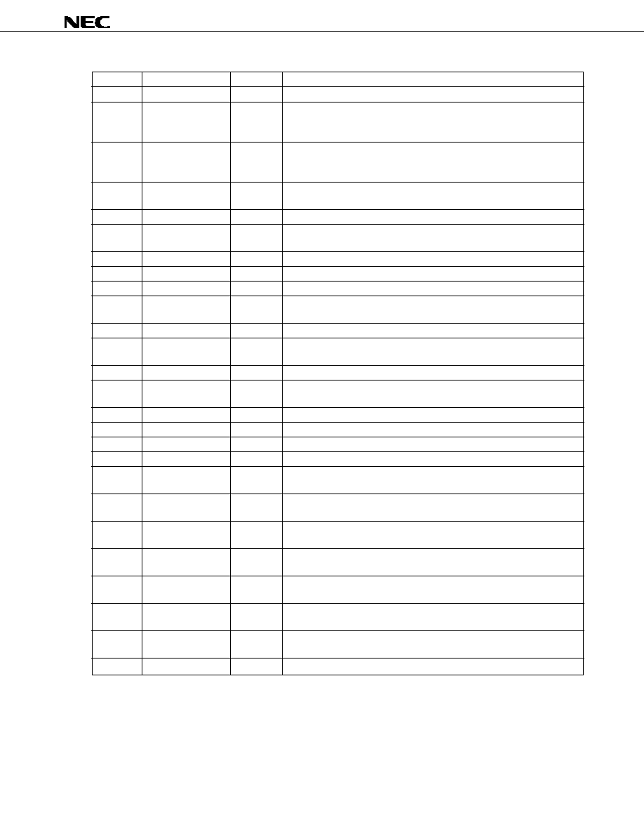
PIN FUNCTIONS
(1/3)
Pin Number
Pin Name
I/O
Function
1
IN1R
I
R-channel analog audio signal input pin 1
2
IN2R
I
R-channel analog audio signal input pin 2
3
IN3R
I
R-channel analog audio signal input pin 3
4
IN4R
I
R-channel analog audio signal input pin 4
5
IN5
I
Analog audio signal (monaural) input pin. This channel accepts audio input
which is input to both left and right channels on the chip.
6
IN4L
I
L-channel analog audio signal input pin 4
7
IN3L
I
L-channel analog audio signal input pin 3
8
IN2L
I
L-channel analog audio signal input pin 2
9
IN1L
I
L-channel analog audio signal input pin 1
10-15
NC
--
No connection
16
MICOL
O
L-channel mic amp output pin. If the L-channel mic amp is not being used,
connect this pin to MICNL pin.
17
MICNL
I
L-channel mic amp inverting input pin. If the L-channel mic amp is not being
used, connect this pin to MICOL pin.
18
MICPL
I
L-channel mic amp noninverting input pin. If the L-channel mic amp is not
being used, connect this pin to VXLO pin.
19
RBW
O
Output pin for signal that specifies the bus driver's direction. Output is at
high level when DATA5 to DATA0 are input pins and is at low level when
DATA5 to DATA0 are output pins. If not used, leave unconnected.
20
OEB
O
Bus driver enable signal output pin. When data input to DATA5 to DATA0
is enabled, output is at low level. If not used, leave unconnected.
21, 22
NC
--
No connection
23
WB
I
Input pin for parallel interface's data write signal. Used for input of low-level
signals when addresses are written to the volume setting register and when
data is written.
24
RB
I
Input pin for parallel interface's data read signal. Used for input of low-level
signals when data is read from the volume setting register.
25
CSB
I
Input pin for parallel interface's chip select signal. Active low. When the
input signal is at high level, DATA5 to DATA0 are set for high impedance.
26
SELR
I
Input pin for signal that specifies the target register for parallel data input and
output. Specifies an address register when the input signal is at low level,
or a data register when the input signal is at high level.
27, 28
TEST1, TEST2
I
Test mode setting pins. These pins set the test mode when at high level.
When not used (i.e., during normal operation mode), connect these pins to
GND.
29
RSTB
I
Reset signal input pin. A reset occurs when a low pulse (pulse width of 1/
(8 fs) or greater) is input after starting MCLK. The case when a reset is
necessary is not only power-on but also an occurrence of disturbance in
master clock due to changing f
S
(sampling frequency). When input is at low
level, power down mode is set to reduce power consumption.
30
NC
--
No connection
µ
PD63310
5
(2/3)
Pin Number
Pin Name
I/O
Function
31
MCLK
I
Master clock input pin. Used for input of 256-fs clock (duty: 40 to 60%).
32
LRCLK
O
Serial interface's frame sync clock output pin.
Used for L channel data I/O when LRCLK = low level
Used for R channel data I/O when LRCLK = high level
33
BCLK
O
Serial interface's bit sync clock output pin.
Used for I/O of audio data from SI and SO in sync with BCLK. BCLK is
generated on-chip as MCLK divided by eight.
34
SI
I
Serial interface's data input pin. Used for serial input (synchronized with
BCLK) of audio data (two's complement, MSB first).
35
NC
--
No connection
36
SO
O
Serial interface's data output pin. Used for serial output (synchronized with
BCLK) of audio data (two's complement, MSB first).
37
DV
DD
--
Digital power supply pin. Used for input voltage range of +3 to +5.5 V.
38-40
NC
--
No connection
41, 42
DGND1, DGND2
G
Digital ground pins.
43-48
DATA5-DATA0
I/O
Parallel data I/O pins. Used for input/output of address data and volume
setting data.
49-53
NC
--
No connection
54
DACR
O
R-channel DAC output pin. When this pin is used, the R-channel DAC output
can be monitored without attenuation regardless of the volume setting.
55
OUTR
O
R-channel analog audio output pin.
56
DACL
O
L-channel DAC output pin. When this pin is used, the L-channel DAC output
can be monitored without attenuation regardless of the volume setting.
57
OUTL
O
L-channel analog audio output pin.
58, 59
AGND5, AGND4
G
Analog ground pins.
60
AV
DD
--
Analog power supply pin. Used for input voltage range of +3 to +5.5 V.
61, 62
NC
--
No connection
63
VRRI
I
Reference voltage input pin for R-channel DAC. This pin is usually connected
to VRRO pin.
64
VRRO
O
Reference voltage output pin for R-channel DAC. Output is 1.4 V (TYP.).
Connects to analog GND via a bypass capacitor.
65
VRLI
I
Reference voltage input pin for L-channel DAC. This pin is usually connected
to VRLO pin.
66
VRLO
O
Reference voltage output pin for L-channel DAC. Output is 1.4 V (TYP.).
Connects to analog GND via a bypass capacitor.
67
VXRI
I
Reference voltage input pin for R-channel ADC. This pin is usually connected
to VXRO pin.
68
VXRO
O
Reference voltage output pin for R-channel ADC. Output is 1.4 V (TYP.).
Connects to analog GND via a bypass capacitor.
69
VXLI
I
Reference voltage input pin for L-channel ADC. This pin is usually connected
to VXLO pin.
70
NC
--
No connection

µ
PD63310
6
(3/3)
Pin Number
Pin Name
I/O
Function
71
VXLO
O
Reference voltage output pin for L-channel ADC. Output is 1.4 V (TYP.).
Connects to analog GND via a bypass capacitor.
72
AGND3
G
Analog ground pin.
73
NC
--
No connection
74, 75
AGND2, AGND1
G
Analog ground pins.
76
MICPR
I
R-channel mic amp noninverting input pin. If the R-channel mic amp is not
being used, connect this pin to VXRO pin.
77
MICNR
I
R-channel mic amp inverting input pin. If the R-channel mic amp is not being
used, connect this pin to MICOR pin.
78
MICOR
O
R-channel mic amp output pin. If the R-channel mic amp is not being used,
connect this pin to MICNR pin.
79, 80
NC
--
No connection

µ
PD63310
7
1. DESCRIPTION OF OPERATIONS
1.1 Analog Input Block
The analog input block enables signal input from two channels. Four different stereo signals (IN1 to IN4) and a
monaural signal (IN5) can be mixed and input via these channels. The volume can be adjusted for each analog signal,
and the sum of the volume settings is input to the ADC. A 6-bit signal is used to adjust the volume within an adjustment
range (in 1.5-dB steps) from ≠46.5 dB to 0 dB, plus a mute setting. A low-noise mic amp (variable gain width: 10 to 30
dB) is provided on-chip for mic input.
1.2 Analog Output Block
The analog output block enables signal output from two channels. Five different analog signals (IN1 to IN4 and DAC)
can be mixed and output via these channels. The volume can be adjusted for each analog signal, and the sum of the
volume settings is output (via OUTL and OUTR pins). A 6-bit signal is used to adjust the volume within an adjustment
range (in 1.5-dB steps) from ≠46.5 dB to 0 dB, plus a mute setting. The output from the DAC (via DACL and DACR pins)
can be monitored directly.
1.3 Digital Interface
A serial interface for audio is supported for input and output of digital audio data (two's complement, MSB first).
BCLK and LRCLK are automatically generated on chip from the master clock that is supplied to MCLK pin from an
external source. BCLK and LRCLK are used by the ADC and DAC. In other words, the ADC's and DAC's sampling
frequency is determined based on the master clock and cannot be set independently of it.
A parallel interface is used for input and output of the 6-bit data used for volume adjustments. The target registers for
parallel data I/O are selected via the SELR pin. This pin selects an address register when at low level and a data register
when at high level.
OEB is output as the bus driver's enable signal and RBW is output as the bus driver's direction specification signal.
Use this pin as necessary. If it is not used, leave it unconnected.
When the clock (data) input to the MCLK and SI pins has been stopped, set these pins to either high level or low level
(if necessary, connect via a resistance to DV
DD
or DGND).
(1) Serial interface
BCLK
LRCLK
SI, SO
15 14 13 12
L-channel data
4
3
2
1
0
15 14 13 12
R-channel data
4
3
2
1
0
LSB
LSB
(2) Parallel interface
(I)
(I)
(I)
(O)
(O)
CSB
RB
WB
OEB
RBW
(I/O)
DATA5-
DATA0

µ
PD63310
8
1.4 Volume Setting Register Addresses
After the power is turned on and a reset has been input, all volume settings are set to mute mode. Therefore, it may
be necessary to specify volume settings before inputting signals. Write data to the volume setting registers that correspond
to the analog input pins and analog output pins to be used.
Since the ADC's full scale analog input signal amplitude voltage is 1.4 V (TYP.), it may be necessary to specify a
volume setting whereby the signal amplitude's maximum voltage (after mixing) is no more than 1.4 V, especially when
several analog signals are input to the ADC after mixing.
The addresses of the various volume setting registers are specified via the 6-bit parallel data that is input from the
DATA5 to DATA0 pins during low-level input to the SELR pin. The volume setting registers corresponding to these
addresses are listed below.
0
: IN1L control register
1
: IN1R control register
2
: IN2L control register
3
: IN2R control register
4
: IN3L control register
5
: IN3R control register
6
: IN4L control register
7
: IN4R control register
8
: IN5 control register
9
: IN1L-OUTL control register
10 : IN1R-OUTR control register
11
: IN2L-OUTL control register
12 : IN2R-OUTR control register
13 : IN3L-OUTL control register
14 : IN3R-OUTR control register
15 : IN4L-OUTL control register
16 : IN4R-OUTR control register
17 : DACL-OUTL control register
18 : DACR-OUTR control register

µ
PD63310
9
1.5 Volume Setting Register Data (Command Types)
The data in the volume setting registers is written and read based on 6-bit parallel data that is input and output via the
DATA5 to DATA0 pins when the SELR pin is set for high level input. The data (commands) in the various volume setting
registers are described below.
0:
D5
D4
D3
D2
D1
D0
D4 to D0 indicate the data used to control gain in the IN1L register's input signal, with codes corresponding
to the gain levels listed in Table 1-1 below. When D5 is "1", mute mode is set.
Table 1-1. Correspondence of Codes and Gain Levels
D5
D4
D3
D2
D1
D0
Gain
0
0
0
0
0
0
0 dB
0
0
0
0
0
1
≠1.5 dB
0
0
0
0
1
0
≠3.0 dB
|
|
|
|
|
|
|
0
1
1
1
1
0
≠45.0 dB
0
1
1
1
1
1
≠46.5 dB
1
0
0
0
0
0
MUTE
Note
1
◊
◊
◊
◊
◊
MUTE
Note
Default value
Remark
◊
: Don't care
1:
D5
D4
D3
D2
D1
D0
D4 to D0 indicate the data used to control gain in the IN1R register's input signal, with codes corresponding
to the gain levels listed in Table 1-1. Mute mode is set when D5 = 1.
2:
D5
D4
D3
D2
D1
D0
D4 to D0 indicate the data used to control gain in the IN2L register's input signal, with codes corresponding
to the gain levels listed in Table 1-1. Mute mode is set when D5 = 1.
3:
D5
D4
D3
D2
D1
D0
D4 to D0 indicate the data used to control gain in the IN2R register's input signal, with codes corresponding
to the gain levels listed in Table 1-1. Mute mode is set when D5 = 1.
4:
D5
D4
D3
D2
D1
D0
D4 to D0 indicate the data used to control gain in the IN3L register's input signal, with codes corresponding
to the gain levels listed in Table 1-1. Mute mode is set when D5 = 1.
5:
D5
D4
D3
D2
D1
D0
D4 to D0 indicate the data used to control gain in the IN3R register's input signal, with codes corresponding
to the gain levels listed in Table 1-1. Mute mode is set when D5 = 1.
6:
D5
D4
D3
D2
D1
D0
D4 to D0 indicate the data used to control gain in the IN4L register's input signal, with codes corresponding
to the gain levels listed in Table 1-1. Mute mode is set when D5 = 1.

µ
PD63310
10
7:
D5
D4
D3
D2
D1
D0
D4 to D0 indicate the data used to control gain in the IN4R register's input signal, with codes corresponding
to the gain levels listed in Table 1-1. Mute mode is set when D5 = 1.
8:
D5
D4
D3
D2
D1
D0
D4 to D0 indicate the data used to control gain in the IN5 register's input signal, with codes corresponding
to the gain levels listed in Table 1-1. Mute mode is set when D5 = 1.
9:
D5
D4
D3
D2
D1
D0
D4 to D0 indicate data that controls the gain when mixing the IN1L register's input signal with the L-channel
DAC's output signal, with codes corresponding to the gain levels listed in Table 1-1. Mute mode is set when
D5 = 1.
10:
D5
D4
D3
D2
D1
D0
D4 to D0 indicate data that controls the gain when mixing the IN1R register's input signal with the R-channel
DAC's output signal, with codes corresponding to the gain levels listed in Table 1-1. Mute mode is set when
D5 = 1.
11:
D5
D4
D3
D2
D1
D0
D4 to D0 indicate data that controls the gain when mixing the IN2L register's input signal with the L-channel
DAC's output signal, with codes corresponding to the gain levels listed in Table 1-1. Mute mode is set when
D5 = 1.
12:
D5
D4
D3
D2
D1
D0
D4 to D0 indicate data that controls the gain when mixing the IN2R register's input signal with the R-channel
DAC's output signal, with codes corresponding to the gain levels listed in Table 1-1. Mute mode is set when
D5 = 1.
13:
D5
D4
D3
D2
D1
D0
D4 to D0 indicate data that controls the gain when mixing the IN3L register's input signal with the L-channel
DAC's output signal, with codes corresponding to the gain levels listed in Table 1-1. Mute mode is set when
D5 = 1.
14:
D5
D4
D3
D2
D1
D0
D4 to D0 indicate data that controls the gain when mixing the IN3R register's input signal with the R-channel
DAC's output signal, with codes corresponding to the gain levels listed in Table 1-1. Mute mode is set when
D5 = 1.
15:
D5
D4
D3
D2
D1
D0
D4 to D0 indicate data that controls the gain when mixing the IN4L register's input signal with the L-channel
DAC's output signal, with codes corresponding to the gain levels listed in Table 1-1. Mute mode is set when
D5 = 1.
16:
D5
D4
D3
D2
D1
D0
D4 to D0 indicate data that controls the gain when mixing the IN4R register's input signal with the R-channel
DAC's output signal, with codes corresponding to the gain levels listed in Table 1-1. Mute mode is set when
D5 = 1.

µ
PD63310
11
17:
D5
D4
D3
D2
D1
D0
D4 to D0 indicate data that controls the gain when outputting the L-channel DAC's output signal to OUTL,
with codes corresponding to the gain levels listed in Table 1-1. Mute mode is set when D5 = 1.
18:
D5
D4
D3
D2
D1
D0
D4 to D0 indicate data that controls the gain when outputting the R-channel DAC's output signal to OUTR,
with codes corresponding to the gain levels listed in Table 1-1. Mute mode is set when D5 = 1.
1.6 Test Mode
Test mode is set (and MCLK input is required) when the TEST1 and TEST2 pins are at high level. When in test mode,
the IC internally inputs the ADC's output directly to the DAC (via an analog loopback). This analog loopback enables
verification of analog circuit operations and the volume settings.

µ
PD63310
12
2. SYSTEM CONNECTIONS
2.1 Analog Input Block
A frequency that is one half of the master clock (MCLK) frequency is used as the ADC's and DAC's oversampling
frequency. Accordingly, if there is no input of high-frequency noise that is close to MCLK/2 (= 128 fs), the filter (LPF)
inserted before the analog block can be omitted (see Figure 2-1).
The analog signal input pins (pins 1 to 9) are internally biased to 1.4 V (TYP.), so a coupling capacitor (1 to 4.7
µ
F)
should be inserted.
The full scale analog input signal level is 1.4 V
p-p
(TYP.). Adjust the transmitting side's level so that the amplitude of
the signal that is input to an analog audio signal input pin does not exceed 1.4 V
p-p
. In particular, if this signal's amplitude
exceeds 2.8 V
p-p
, the analog signal input pin's voltage may become less than 0 V during negative amplitude, which may
prevent the volume control from operating normally (such as when there is signal leakage during mute mode).
Analog signal input pins that are not used should be left unconnected or connected to a GND pin via a capacitor.
Figure 2-1. Analog Input Block Connection Example (Using IN1R Pin)
IN1R etc.
+
µ
4.7 F
2.2 Mic Amp
The mic amp's gain can be adjusted (between 10 dB (MIN.) and 30 dB (MAX.)) via an external resistor. The gain
setting is adjusted by changing R1. R2 is fixed at 100 k
(see Figure 2-2). Gain is calculated via the following
expression.
Mic amp gain calculation: A
V
= 20 log ((R2 + R1)/R1) [dB]
Since the mic amp is independent from other blocks, if the mic amp's output is input to the ADC (or is mixed with
output from the DAC), the mic amp's output pin should be connected via a coupling capacitor to one of the analog signal
input pins (see Figure 2-1).
Separate the unused mic amp from R1 and the electrolytic capacitors (shown in Figure 2-2) and set 0
for R2.
Figure 2-2. Mic Amp Connection Example (Using Right Side)
To VXRO
µ
R2 = 100 k
R1 = 10 k
R1 = 10 k
4.7 F
µ
4.7 F
R2 = 100 k
MICPR
MICNR
MICOR
To analog signal input pins
+
+
Remark When the above example is a constant, the mic amp's gain becomes about 21 dB.

µ
PD63310
13
2.3 Analog Output Block
The analog audio output pins (OUTL and OUTR) and the DAC output pins (DACL and DACR) are internally biased to
1.4 V (TYP.), so an output coupling capacitor should be inserted to cut the DC component (see Figure 2-3).
The out-of-band component of the output signals from these analog pins is attenuated by a post filter (LPF) in the IC,
so there is no need for an external LPF.
Set the load resistance to at least 20 k
(the speakers cannot be directly driven, so insert a power amp IC before the
speaker).
Analog audio output pins and DAC output pins that are not used can be left unconnected.
Figure 2-3. Analog Output Block Connection Example
OUTL etc.
+
µ
4.7 F
33 k
2.4 Use Cautions
When changing the volume (addresses 17 and 18) between the DAC output and the output mixer, noise ("pop noise")
may be output from an analog audio output pins (OUTL or OUTR). Such noise is due to the output offset voltage of an
on-chip DAC.
If this noise is audible enough to be a problem, take the following measures.
(1) Set mute mode for the volume (addresses 17 and 18) between the DAC output and the output mixer.
(2) Connect the DAC output pins (DACL and DALR) via a capacitor to a pair of unused analog input pins
(such as IN4L and IN4R).
(3) Adjust the volume (such as addresses 15 and 16) between the analog input pins connected as described
in (2) above and the output mixer to adjust the DAC output volume.

µ
PD63310
14
3. ELECTRICAL SPECIFICATIONS
Absolute Maximum Ratings (unless otherwise specified, DGND = AGND = 0 V)
Parameter
Symbol
Conditions
Rating
Unit
Power supply voltage
V
DD
All V
DD
pins
≠0.3 to +7.0
V
Analog input voltage
V
AIN
All analog input pins
≠0.3 to V
DD
+0.3
V
Digital input voltage
V
DIN
All digital input pins
≠0.3 to V
DD
+0.3
V
Applied voltage to analog output pin
V
AOUT
All analog output pins
≠0.3 to V
DD
+0.3
V
Applied voltage to digital output pin
V
DOUT
All digital output pins
≠0.3 to V
DD
+0.3
V
Operating ambient temperature
T
A
≠20 to +80
∞
C
Storage temperature
T
stg
≠65 to +150
∞
C
Caution If the absolute maximum rating for any of the above parameters is exceeded even momentarily,
it may adversely affect the quality of this product. In other words, these absolute maximum
ratings have been set to prevent physical damage to the product. Do not use the product in
such a way as to exceed any of these ratings.
Recommended Operating Conditions (unless otherwise specified, DGND = AGND = 0 V, load capacitance =
20 pF, and on-chip reference voltage power supply is used)
Parameter
Symbol
Conditions
MIN.
TYP.
MAX.
Unit
Power supply voltage
V
DD
All V
DD
pins
3.0
5.5
V
Operating ambient temperature
T
A
≠20
25
80
∞
C
Master clock frequency
f
MCLK
256 fs
0.512
12.288
MHz
Sampling frequency
fs
2
48
kHz
Digital input voltage (high level)
V
IH
When V
DD
= 5.0 V
4.5
5
V
Digital input voltage (low level)
V
IL
When V
DD
= 5.0 V
0
1.0
V
Digital input voltage (high level)
V
IH
When V
DD
= 3.3 V
2.64
3.3
V
Digital input voltage (low level)
V
IL
When V
DD
= 3.3 V
0
0.66
V
RSTB rise time
t
rRSTB
Time required to change from 10%
--
1
µ
s
to 90% of V
DD
Analog input signal voltage
V
I
All analog input pins
--
1.4
V
p-p
ADC input signal voltage
V
IADC
Mixer output section (before ADC)
--
1.4
V
p-p
Analog output signal voltage
V
O
OUTL and OUTR pins
--
1.4
V
p-p
(mixer output section)
Analog output pin load resistance
RL
All analog output pins
20
--
k
Mic amp voltage gain
A
VMIC
10
20
30
dB

µ
PD63310
15
DC Characteristics (unless otherwise specified, T
A
= ≠20 to +80
∞
C, DV
DD
= AV
DD
= 3.0 to 5.5 V, DGND = AGND
= 0 V)
(1) Power consumption
Parameter
Symbol
Conditions
MIN.
TYP.
MAX.
Unit
Operating current
I
DD
When V
DD
= 5.0 V
--
50
70
mA
Operating current
I
DD
When V
DD
= 3.0 V
--
40
60
mA
Standby current
I
DDstb
Power down mode
--
1.5
2
mA
(2) Digital block
Parameter
Symbol
Conditions
MIN.
TYP.
MAX.
Unit
Input leakage current
I
LI
When V
DD
= 5.0 V and V
I
= 5.0 to 0.0 V
≠5.0
+5.0
µ
A
Output leakage current
I
LO
When V
DD
= 5.0 V and V
O
= 5.0 to 0.0 V
≠5.0
+5.0
µ
A
(high impedance)
High-level output current
I
OH
When V
DD
= 5.0 V and V
O
= 4.0 V
≠2.0
--
mA
Low-level output current
I
OL
When V
DD
= 5.0 V and V
O
= 0.4 V
--
+2.0
mA
High-level output voltage
V
OH
When V
DD
= 5.0 V and I
O
= ≠2.0 mA
4.0
--
V
Low-level output voltage
V
OL
When V
DD
= 5.0 V and I
O
= 2.0 mA
--
0.4
V
High-level output voltage
V
OH
When V
DD
= 3.3 V and I
O
= ≠2.0 mA
2.64
--
V
Low-level output voltage
V
OL
When V
DD
= 3.3 V and I
O
= 2.0 mA
--
0.4
V
(3) Analog block
Parameter
Symbol
Conditions
MIN.
TYP.
MAX.
Unit
Reference power supply
V
XL (R)
VXRO and VXLO pins
1.35
1.4
1.45
V
output voltage, AD side
Reference power supply
V
RL (R)
VRRO and VRLO pins
1.35
1.4
1.45
V
output voltage, DA side
Input resistance 1
R
I1
IN1L, IN2L, IN3L, IN4L, IN1R, IN2R, IN3R,
6.5
10
15
k
and IN4R pins
Input resistance 2
R
I2
IN5 pin
13
20
30
k

µ
PD63310
16
Transmission Characteristics (unless otherwise specified, T
A
= ≠20 to +80
∞
C, DV
DD
= AV
DD
= 3.0 to 5.5 V, DGND
= AGND = 0 V, master clock = 12.288 MHz, and on-chip reference voltage power supply is used)
(1) AD side
Parameter
Symbol
Conditions
MIN.
TYP.
MAX.
Unit
AD peak S/N
SNP
X
Signal = 1 kHz, in 0 to 20 kHz bandwidth
60
75
--
dB
AD dynamic range
SN
X
≠60 dB input
60
75
--
dB
AD idle noise
ICN
X
--
≠75
≠60
dB
AD absolute gain
G
X
Signal = 1 kHz, 0 dB input
≠1.0
±
0.5
+1.0
dB
AD relative gain 1
G
VX
1
≠22.5 to ≠1.5 dB (0-dB reference)
≠2.0
±
1.0
+2.0
dB
AD relative gain 2
G
VX
2
≠46.5 to ≠24.0 dB (0-dB reference)
≠5.0
±
2.0
+5.0
dB
AD frequency gain
GR
X
0 to 20 kHz
≠0.5
±
0.1
+0.5
dB
characteristic
AD total harmonic distortion
THD
X
Signal = 1 kHz, 0 dB input
--
≠50
≠40
dB
AD full-scale analog input
VIFS
Signal = 1 kHz, 0 dB input
1.35
1.4
1.45
V
p-p
amplitude
AD offset voltage
V
OFFX
≠100
±
10
+100
mV
(2) DA side
Parameter
Symbol
Conditions
MIN.
TYP.
MAX.
Unit
DA peak S/N
SNP
R
Signal = 1 kHz, in 0 to 20 kHz bandwidth
60
75
--
dB
DA dynamic range
SN
R
≠60 dB input
60
75
--
dB
DA idle noise
ICN
R
--
≠75
≠60
dB
DA absolute gain
G
R
Signal = 1 kHz, 0 dB input
≠1.0
±
0.5
+1.0
dB
DA relative gain 1
G
VR
1
≠22.5 to ≠1.5 dB (0-dB reference)
≠2.0
±
1.0
+2.0
dB
DA relative gain 2
G
VR
2
≠46.5 to ≠24.0 dB (0-dB reference)
≠5.0
±
3.0
+5.0
dB
DA frequency gain
GR
R
0 to 20 kHz
≠0.5
±
0.2
+0.5
dB
characteristic
DA total harmonic distortion
THD
R
Signal = 1 kHz, 0 dB input
--
≠50
≠40
dB
DA full-scale analog output
VOFS
Signal = 1 kHz, 0 dB input
1.35
1.4
1.45
V
p-p
amplitude
DA offset voltage
V
OFFR
≠100
±
30
+100
mV

µ
PD63310
17
AC Characteristics (unless otherwise specified, T
A
= ≠20 to +80
∞
C, DV
DD
= AV
DD
= 3.0 to 5.5 V, DGND = AGND
= 0 V)
Parameter
Symbol
Conditions
MIN.
TYP.
MAX.
Unit
RSTB-CSB setup time
t
RSUC
0
--
ns
RSTB-SELR setup time
t
RSUS
0
--
ns
CSB-WB setup time
t
CSSUW
0
--
ns
SELR-WB setup time
t
SESU
0
--
ns
SELR-WB hold time
t
SEHD
60
--
ns
Time between SELR and WB
t
BSW
0
--
ns
WB-CSB hold time
t
CSHD
60
--
ns
WB low-level width
t
STW
120
--
ns
RB low-level width
t
RSTW
200
--
ns
Data valid time after WB
t
WDDV
0
90
ns
DATA-WB setup time
t
WDSU
30
--
ns
WB-DATA hold time
t
DHDW
30
--
ns
Time between SELR and RB
t
BSR
0
--
ns
RB-SELR hold time
t
SEHDR
60
--
ns
Data delay time after RB
t
RDDV
0
150
ns
RB-DATA hold time
t
DHDR
0
20
ns
DATA-CSB hold time
t
CSHDR
30
--
ns
DATA IN setup time
t
DIS
100
--
ns
DATA IN hold time
t
DIH
100
--
ns
DATA OUT setup time
t
DOD
≠40
+65
ns
DATA OUT hold time
t
BLD
0
45
ns

µ
PD63310
18
Parallel interface write timing 1
RSTB
CSB
SELR
WB
DATA5-
DATA0
OEB
RBW
t
RSUC
t
CSSUW
t
CSHD
t
BSW
t
SEHD
t
SESU
t
STW
t
WDDV
t
WDSU
t
DHDW
t
WDDV
t
WDSU
t
DHDW
t
RSUS

µ
PD63310
19
Parallel interface write timing 2 (when there are continual write cycles while CSB is low)
RSTB
CSB
SELR
WB
DATA5-
DATA0
OEB
RBW
t
RSUC
t
CSSUW
t
BSW
t
SEHD
t
SESU
t
STW
t
WDDV
t
WDSU
t
DHDW
t
WDDV
t
WDSU
t
DHDW
t
RSUS
t
SEHD
t
SESU
the different part from
"Parallel Interface write
timing 1"

µ
PD63310
20
Parallel interface read timing 1
RSTB
CSB
SELR
WB
DATA5-
DATA0
RBW
t
RSUC
t
CSSUW
t
CSHDR
t
BSR
t
SEHD
t
SESU
t
STW
t
WDDV
t
WDSU
t
RDDV
t
DHDR
t
RSTW
t
DHDW
OEB
RB
t
RSUS

µ
PD63310
21
Parallel interface read timing 2 (when there are continual read cycles while CSB is low)
RSTB
CSB
SELR
WB
DATA5-
DATA0
RBW
t
RSUC
t
CSSUW
t
BSR
t
SEHD
t
SESU
t
STW
t
WDDV
t
WDSU
t
RDDV
t
DHDR
t
RSTW
t
DHDW
OEB
RB
t
RSUS
t
SEHDR
t
SESU
the different part from
"Parallel Interface read
timing 1"

µ
PD63310
22
Serial interface input timing
BCLK
t
DIS
SI
t
DIH
Serial interface output timing
BCLK
SO
LRCLK
t
DOD
t
BLD
t
BLD

µ
PD63310
23
4. APPLICATION CIRCUIT EXAMPLE
Remark
: Analog ground
: Digital ground
+
µ
0.1 F
10 k
80
79
78
77
76
75
74
73
72
69
70
71
68
67
64
65
66
61
62
63
21
22
23
24
25
26
27
28
29
32
31
30
33
34
37
36
35
40
39
38
1
2
3
4
5
6
7
8
9
10
11
12
13
14
15
16
17
18
19
20
60
59
58
57
56
55
54
53
52
51
50
49
48
47
46
45
44
43
42
41
IN1R
IN2R
IN3R
IN4R
IN5
IN4L
IN3L
IN2L
IN1L
NC
NC
NC
NC
NC
NC
MICOL
MICNL
MICPL
RBW
OEB
AV
DD
AGND4
AGND5
OUTL
DACL
OUTR
DACR
NC
NC
NC
NC
NC
DATA0
DATA1
DATA2
DATA3
DATA4
DATA5
DGND2
DGND1
NC
NC
WB
RB
CSB
SELR
TEST1
TEST2
RSTB
NC
MCLK
LRCLK
BCLK
SI
NC
SO
DV
DD
NC
NC
NC
NC
NC
MICOR
MICNR
MICPR
AGND1
AGND2
NC
AGND3
VXLO
NC
VXLI
VXRO
VXRI
VRLO
VRLI
VRRO
VRRI
NC
NC
µ
4.7 F
10 k
100 k
+
µ
4.7 F
◊
9
+
+
+
+
+
+
+
+
+
+
100 k
10 k
10 k
µ
4.7 F
µ
4.7 F
100 k
µ
0.1 F
µ
4.7 F
D0
D1
D2
D3
D4
D5
6
+
+
+
+
µ
4.7 F
33 k
◊
4
+
+
+
+
µ
4.7 F
µ
4.7 F
◊
4
100 k
To VXRO
µ
0.1 F
◊
4
µ
4.7 F
◊
4 (tantalum)
R-ch
mic input
R-ch
line input
Monaural
line input
L-ch
line input
R-ch
line output
L-ch
line output
L-ch
mic input
To VXLO
Microcontroller
digital
I/O
Reset
Audio
digital
I/O
+
+
+

µ
PD63310
24
5. RECOMMENDED LAYOUT PATTERN
When laying out the power supply lines and GND lines on the circuit board, refer to the following figure concerning
the layout of bypass capacitors.
Figure 5-1. Diagram of Recommended Bypass Capacitor Connections (Top View)
+
+
+
+
+
+
AV
DD
AGND4
AGND5
VRRI
VRRO
VRLI
VRLO
VXRI
VXRO
VXLI
VXLO
AGND3
AGND2
AGND1
SYSTEM
ANALOG GND
DIGITAL GND
DV
DD
DGND2
DGND1
Remark
+
(4.7
µ
F) : Tantalum capacitor
(0.1
µ
F) : Chip ceramic capacitor

µ
PD63310
25
6. PACKAGE DRAWING
S80GK-50-9EU
NOTE
Each lead centerline is located within 0.10 mm (0.004 inch) of
its true position (T.P.) at maximum material condition.
ITEM
MILLIMETERS
INCHES
A
B
C
D
F
G
H
I
J
K
14.0±0.2
12.0±0.2
1.25
0.22±0.05
0.10
12.0±0.2
L
M
0.10
0.145±0.05
1.0±0.2
0.5 (T.P.)
0.5±0.2
N
1.0±0.05
14.0±0.2
1.25
P
0.551±0.008
0.472
0.551±0.008
0.049
0.049
0.009
0.004
0.020 (T.P.)
0.039
0.020
0.006
0.004
0.040
+0.002
≠0.003
0.472
+0.008
≠0.009
Q
0.1±0.05
0.004±0.002
S
1.2 MAX.
0.048 MAX.
+0.002
≠0.003
+0.009
≠0.008
+0.009
≠0.008
+0.009
≠0.008
+0.002
≠0.003
R
3∞
3∞
+7∞
≠3∞
+7∞
≠3∞
80 PIN PLASTIC TQFP (FINE PITCH) ( 12)
B
60
A
41
40
21
61
80
1
20
C
D
G
J
H
I
M
F
N
P
K
L
M
S
R
Q
detail of lead end

µ
PD63310
26
7. RECOMMENDED SOLDERING CONDITIONS
This product should be soldered and mounted under the conditions recommended in the table below.
For details of recommended soldering conditions, refer to the information document Semiconductor Device Mounting
Technology Manual (C10535E).
For soldering methods and conditions other than those recommended below, contact our sales representative.
Table 7-1. Soldering Conditions for Surface Mounting Type
µ
PD63310GK-9EU: 80-pin plastic TQFP (FINE PITCH) (12
◊
12 mm)
Soldering Method
Soldering Conditions
Symbol
Infrared reflow
Package peak temperature: 235
∞
C, Reflow time: 30 seconds or below
IR35-107-2
(at 210
∞
C or higher), Number of reflow processes: 2 max., Exposure limitNote:
7 days (after that, prebaking is necessary at 125
∞
C for 10 hours)
VPS
Package peak temperature: 215
∞
C, Reflow time: 40 seconds or below
VP15-107-2
(at 200
∞
C or higher), Number of reflow processes: 2 max., Exposure limitNote:
7 days (after that, prebaking is necessary at 125
∞
C for 10 hours)
Pin partial heating
Pin temperature: 300
∞
C or below, Time: 3 seconds or below (per device side)
--
Note
The number of days for storage after the dry pack has been opened. Storage conditions are 25
∞
C and
65% RH max.
Caution Do not use two or more soldering methods in combination (except for pin partial heating
method).

µ
PD63310
27
NOTES FOR CMOS DEVICES
1
PRECAUTION AGAINST ESD FOR SEMICONDUCTORS
Note: Strong electric field, when exposed to a MOS device, can cause destruction
of the gate oxide and ultimately degrade the device operation. Steps must
be taken to stop generation of static electricity as much as possible, and
quickly dissipate it once, when it has occurred. Environmental control must
be adequate. When it is dry, humidifier should be used. It is recommended
to avoid using insulators that easily build static electricity. Semiconductor
devices must be stored and transported in an anti-static container, static
shielding bag or conductive material. All test and measurement tools
including work bench and floor should be grounded. The operator should
be grounded using wrist strap. Semiconductor devices must not be touched
with bare hands. Similar precautions need to be taken for PW boards with
semiconductor devices on it.
2
HANDLING OF UNUSED INPUT PINS FOR CMOS
Note: No connection for CMOS device inputs can be cause of malfunction. If no
connection is provided to the input pins, it is possible that an internal input
level may be generated due to noise, etc., hence causing malfunction. CMOS
device behave differently than Bipolar or NMOS devices. Input levels of
CMOS devices must be fixed high or low by using a pull-up or pull-down
circuitry. Each unused pin should be connected to V
DD
or GND with a
resistor, if it is considered to have a possibility of being an output pin. All
handling related to the unused pins must be judged device by device and
related specifications governing the devices.
3
STATUS BEFORE INITIALIZATION OF MOS DEVICES
Note: Power-on does not necessarily define initial status of MOS device. Produc-
tion process of MOS does not define the initial operation status of the device.
Immediately after the power source is turned ON, the devices with reset
function have not yet been initialized. Hence, power-on does not guarantee
out-pin levels, I/O settings or contents of registers. Device is not initialized
until the reset signal is received. Reset operation must be executed imme-
diately after power-on for devices having reset function.

µ
PD63310
The application circuits and their parameters are for reference only and are not intended for use in actual design-ins.
No part of this document may be copied or reproduced in any form or by any means without the prior written
consent of NEC Corporation. NEC Corporation assumes no responsibility for any errors which may appear in
this document.
NEC Corporation does not assume any liability for infringement of patents, copyrights or other intellectual property
rights of third parties by or arising from use of a device described herein or any other liability arising from use
of such device. No license, either express, implied or otherwise, is granted under any patents, copyrights or other
intellectual property rights of NEC Corporation or others.
While NEC Corporation has been making continuous effort to enhance the reliability of its semiconductor devices,
the possibility of defects cannot be eliminated entirely. To minimize risks of damage or injury to persons or
property arising from a defect in an NEC semiconductor device, customers must incorporate sufficient safety
measures in its design, such as redundancy, fire-containment, and anti-failure features.
NEC devices are classified into the following three quality grades:
"Standard", "Special", and "Specific". The Specific quality grade applies only to devices developed based on a
customer designated "quality assurance program" for a specific application. The recommended applications of
a device depend on its quality grade, as indicated below. Customers must check the quality grade of each device
before using it in a particular application.
Standard: Computers, office equipment, communications equipment, test and measurement equipment,
audio and visual equipment, home electronic appliances, machine tools, personal electronic
equipment and industrial robots
Special:
Transportation equipment (automobiles, trains, ships, etc.), traffic control systems, anti-disaster
systems, anti-crime systems, safety equipment and medical equipment (not specifically designed
for life support)
Specific:
Aircrafts, aerospace equipment, submersible repeaters, nuclear reactor control systems, life
support systems or medical equipment for life support, etc.
The quality grade of NEC devices is "Standard" unless otherwise specified in NEC's Data Sheets or Data Books.
If customers intend to use NEC devices for applications other than those specified for Standard quality grade,
they should contact an NEC sales representative in advance.
Anti-radioactive design is not implemented in this product.
M4 96.5