 | –≠–ª–µ–∫—Ç—Ä–æ–Ω–Ω—ã–π –∫–æ–º–ø–æ–Ω–µ–Ω—Ç: uPD98433 | –°–∫–∞—á–∞—Ç—å:  PDF PDF  ZIP ZIP |
NEW PRODUCTS 7
The
µ
PD98433 incorporates an 8-port, 3-
speed (10 Mbps, 100 Mbps, and 1000
Mbps) Ethernet MAC (Media Access
Controller) function compliant with
international standards (IEEE standard
802.3 1998 Edition), and realizes gigabit
Ethernet transmission and reception at
wire speed on all 8 ports through the use
of a 128-bit
◊
125 MHz high-speed bus
interface for transmission and reception
to and from the upper layer device.
Introduction
Recent years have seen the explosive growth
of the Internet population, the increasing
sophistication of applications, and a rapid
increase in data amounts resulting from the
spread of multimedia contents. To meet the huge
increase in demand for communications, the
Ethernet, which until now has been broadly used
as a LAN (Local Area Network) technology, is
now being widely promoted as the basic
technology of the WAN (Wide Area Network),
MAN (Metropolitan Area Network), and access
network infrastructures. As the number of
broadband access subscribers increases, data
traffic on WAN and MAN networks is expected
to greatly increase, and Ethernet technology that
realizes high-speed and long-distance/wide-area
transmission at low cost, is beginning to gain
acceptance in the market. Concretely, devices
that use high-speed Ethernet switches are used
in (1) high-end routers for backbone networks
that use 10 Gbps-class data transmission speed,
(2) large-capacity transmission systems that use
WDM (Wavelength-Division Multiplexing), and
(3) Ethernet-based FTTx (Fiber-to-the-x),
evidence of the fact that networks that use
Ethernet are increasingly being built in all
directions. Such devices are provided with
gigabit-class Ethernet ports and the number of
such ports is bound to increase in the future.
To answer such market needs, NEC has
developed the
µ
PD98433, an 8-port 10/100/1000
Mbps Ethernet controller LSI that can
remarkably lift the data transmission
performance of network equipment such as
8-PORT 10/100/1000 MBPS ETHERNET
TM
CONTROLLER LSI
µ
PD98433
*
2nd System LSI Division (Published April 2002)
Masaaki Kimura
*
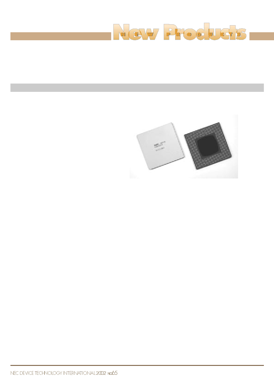
routers and LAN switches (Photo 1).
Outline of
µ
PD98433
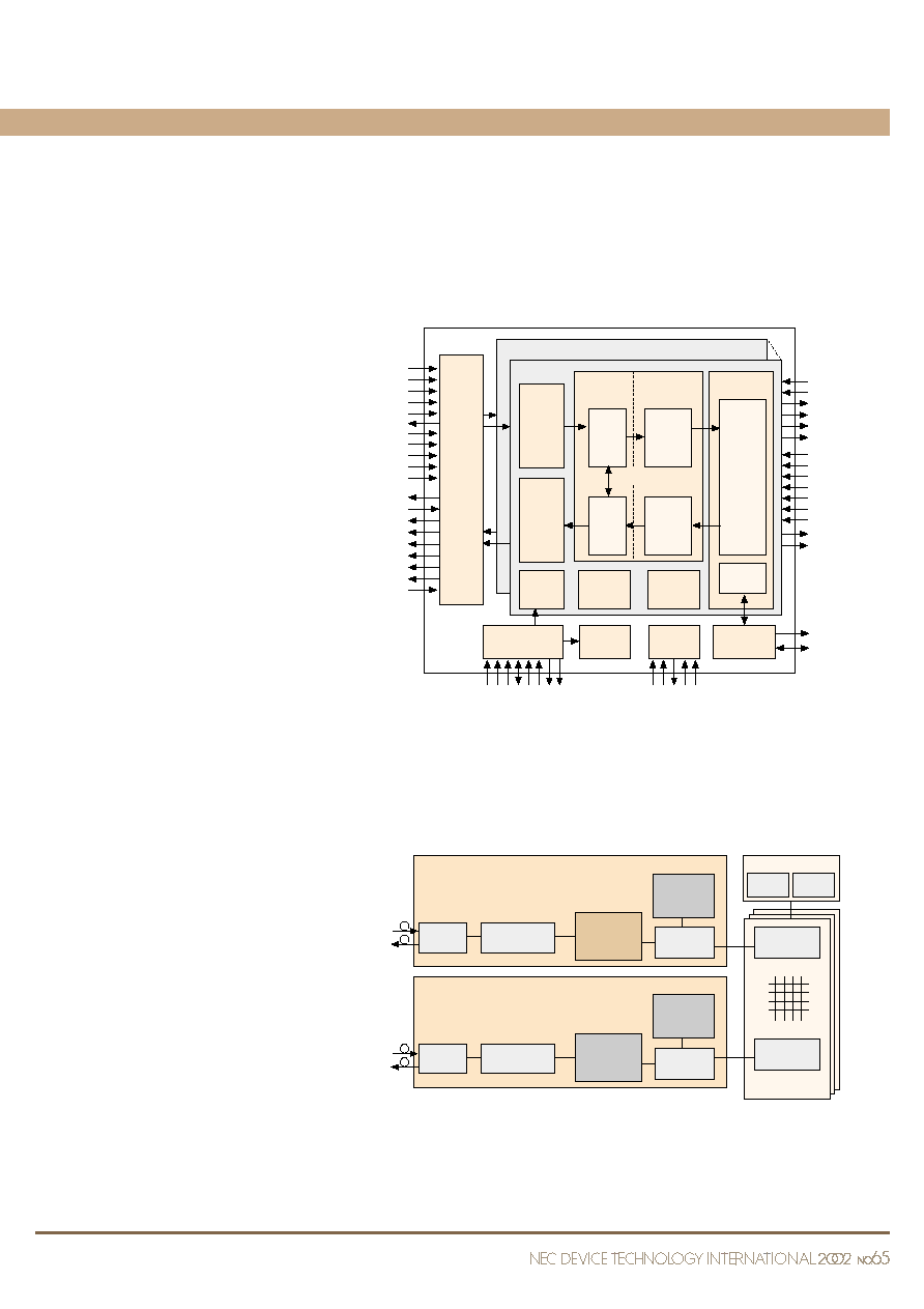
Figure 1 shows the internal block diagram of
the
µ
PD98433. The MAC function of the
µ
PD98433 is positioned at Layer 2 (data link
layer) of the OSI reference model, which
describes the network layer structure. The main
functions are packet transmission and reception,
transmission packet assembly, control packet
assembly, error detection processing and
processing following a conflict during half-
duplex operation, intermediating between MAC
client devices on upper layers and physical layer
devices on lower layers. An original NEC 128-
bit
◊
125 MHz high-speed interface is used for
the interface with upper layer devices, and three
different interfaces, i.e. GMII (Gigabit Media
Independent Interface), MII (Media Independent
Interface), and TBI (Ten Bit Interface), are used
for the interface with lower layer devices. Figure
2 shows a sample switch/router application using
the
µ
PD98433. The application illustrated in this
figure consists of a chassis-type switch/router
configured with line interface modules that use
the
µ
PD98433.
µ
PD98433 Features
1. Support of 3 speeds (10/100/1000 Mbps)
10 Mbps, 100 Mbps, and 1000 Mbps Ethernet
speeds are supported for each port via the MII
interface (10 Mbps and 100 Mbps), the GMII
interface (1000 Mbps), and the TBI interface
using the internal PCS (Physical Coding
Sublayer). These three speeds can be freely set
using the register for each port and they can be
used in mix. The fact that this controller supports
three speeds enables a reduction in both the size
and number of parts required for gigabit Ethernet
equipment.
2. Use of high-speed bus interface
An NEC original 128-bit
◊
125 MHz high-
speed bus interface is incorporated on both the
transmission and reception sides to enable
simultaneous gigabit transmission/reception
(full-duplex operation) on all 8 ports, thus
enabling high-speed transfer of data to/from the
upper layer device with no data loss.
A round robin function is incorporated in the
reception-side interface to the upper layer device.
This round robin function makes it possible to
evenly transfer the data received by all the ports
to the upper layer device in packet units. A
function to skip the round robin sequence is also
provided. This function can be used to read
specific ports in priority over other ports.
3. 6 KB transmit/receive FIFO memory
incorporated in each port
To support gigabit reception processing, each
port includes a 6 KB receive FIFO memory in
Photo 1
µ
PD98433
Port #7
8Port
Transmit
Function
8 B/10 B
Encoder/
Decoder
MII
Management
MII
Management
Tx-FIFO
FIFO
Interface
Port #0
Tx
MAC
Control
MAC
Control
MAC
MAC
Function
PCS
Receive
Function
Rx
MAC
Control
Rx-FIFO
Register
Set
HOST
Interface
Global
Register Set
JTAG
MDC
LINK#
EWRAP[7:0]
TX_EN/TX[9]
TX_EN/TX[8]
TXD[7:0]/TX[7:0]
GTX_CLK
COL
HCS#
HR
W
HA[10:0]
HD[31:0]
RESET#
TMS
TDI
TDO
TCK
TRST#
HCLK
INT#
HACK#
CRS/SIGDET
TX_CLK
RXFCK
RXETH[7:0]
RXPAR
RXFA
RXFDQ[4:0]
RXFD[127:0]
RXFPT[2:0]
RXFEN#
RXFCKOUT
FC[7:0]
RXABT
SKIP
PASS
TXPAR
TXFBA[7:0]
TXFDQ[4:0]
TXFD[127:0]
TXFPT[2:0]
TXFEN#
TXFCK
GTX_REF_CLK
RX_ER/RX[9]
RX_DV/RX[8]
RXD[7:0]/RX[7:0]
RX_CLK1
RX_CLK0
MDIO
MAC
Statistics
Counters
Station
Address
Logic
which multiple Ethernet packets (maximum
length = 1518 bytes) can be stored. By changing
the threshold value set in the FIFO, packets of
up to 9 KB can also be received. A 6 KB FIFO
memory is also incorporated in each port on the
transmission side, reducing the load on the upper
layer device and thus raising the system
performance.
Moreover, arbitration between the transmit/
receive clock from the lower layer device and
the transmit/receive clock from the upper layer
device is also performed by the FIFO.
4. Flow control function
The
µ
PD98433 incorporates a flow control
function compliant with IEEE Std. 802.3 1998
Edition.
If a valid pause control frame is received, the
µ
PD98433 sets the pause timer value included
in the received pause control frame to the chip.
Next, the
µ
PD98433 delays transmission for the
pause interval prescribed by the pause timer. If
the pause timer value included in the received
pause control frame is 0, the
µ
PD98433 restarts
transmission.
On the other hand, pause control frame
transmission can be performed using one of the
following three methods.
(1) Automatic transmission using threshold
value set to receive FIFO
(2) Automatic retransmission of pause control
frame using retransmission interval timer
(3) Direct control via external pin
Using method (1), a threshold value is set to
the receive FIFO in advance and if the amount
of data in the receive FIFO exceeds that value,
the pause frame is automatically transmitted.
Using method (2), if the amount of data in the
receive FIFO did not diminish following
automatic transmission using method (1), the
pause control frame is automatically
retransmitted after the previously set
retransmission interval has elapsed. Using
method (3), regardless of the state of the on-chip
receive FIFO, the pause control frame is
transmitted to the
µ
PD98433 upon direct
instruction from the upper layer device. These
three methods can be used combined.
5. Statistics counter
Fifty-one statistics counters based on RMON-
MIB are incorporated in each port to collect and
manage statistics information such as the traffic
status and error occurrences on the network. This
statistics information is made available to the
upper system. Each statistics counter is updated
Line Interface Module
(LIM)
Line Interface Module
(LIM)
µ
PD98421
Forwarding
Engine
Switch
Chip
Switch
Chip
Switching
Module
CPU
Memory
10/100/1000M
Multi-PHY
10/100/1000M
Multi-MAC
Address Search
Control Module
µ
PD98433
Optical
Module
Optical
Module
µ
PD98421
Forwarding
Engine
10/100M
Multi-PHY
10/100M
Multi-MAC
Address Search
µ
PD98431
Fig. 1 Internal Block Diagram of
µ
PD98433
Fig. 2
µ
PD98433 Application Example
NEW PRODUCTS 7
upon completion of transmission/reception.
Statistics information is read via the host
interface.
6. Various processing functions for reception
packets
A packet filtering function for filtering
reception packets based on the destination
address information and error occurrence
information is provided. In the case of filtering
according to the destination address, filtering can
be set according to the address type (unicast,
multicast, broadcast). Filtering using a
combination of these is also possible, and
reception of all packets can also be set.
Moreover, the status information for each
reception packet can be added to the reception
data. All these settings reduce the reception
packet processing load on the upper system.
Automatic rejection of error packets such as
short packets and CRC error packets can also be
set.
µ
PD98433 System Configuration
The
µ
PD98433 is mainly configured of the
following modules.
Index area
C1.25
y
S
672-
b
x1
M
S
x1
M
S
A
A
A1
A2
A
Detail of part A
B
3-C0.5
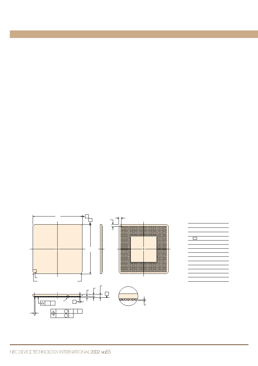
756-pin plastic BGA (45
◊
45) External View
Unit: mm
S
ZD
ZE
AN AL AJ AG AE AC AA W U R
L
J G E C A
AP AM AK AH AF AD AB
V
Y
T P M
N
K H F D B
MILLIMETER
ITEM
D
E
e
A
A1
A2
A4
b
x1
x2
y
ZD
ZE
45.00
±
0.20
45.00
±
0.20
1.27
2.50
±
0.30
0.60
±
0.10
1.90
0.25MIN.
0.75
±
0.15
0.30
0.15
0.20
1.545
1.545
P756S9-127-K6-1
1
2
4
6
8
10
12
14
16
18
20
22
24
26
28
30
32
34
3
5
7
9
11
13
15
17
19
21
23
25
27
29
31
33
e
A4
D
E
A
B
1. MAC module
The MAC module is configured of a main
module that realizes the 10/100/1000 Mbps
Ethernet MAC function, and a module for flow
control compliant with IEEE802.3. The main
MAC functions are packet transmission and
reception, transmission packet assembly, error
detection processing, processing following a
conflict during half-duplex operation, and
VLAN detection. The GMII/MII interface is
supported as the interface with physical layer
devices. Connection to physical layer devices
that have the TBI interface can be done via a
PCS module. The module that performs flow
control transmits and receives flow control
packets. The
µ
PD98433 contains a function that
performs automatic transmission of flow control
packets by setting a threshold value to the receive
FIFO. Flow control packet transmission requests
from upper layer devices are also supported.
2. PCS module
The PCS module performs 8B10B/10B8B
code conversion compliant with IEEE802.3
when a physical layer device is connected using
a TBI interface. An MII management module for
controlling the operation of the PCS module is
included. Auto-negotiation processing of the TBI
interface is performed by the PCS module, and
optimum performance settings can be made by
exchanging information with the other
communication party.
3. Station address logic
The station address logic is a module that
performs address filtering. It performs filtering
using the destination address in received packets.
Filtering can be performed according to the
address type (unicast address, multicast address,
broadcast address).
4. MAC statistics counter module
This module collects and manages statistics
information such as the traffic status and error
occurrences on the network. Statistics
information is provided to the upper layer system
via the host interface.
5. Transmit/receive FIFO
On-chip 6 KB transmit and 6 KB receive
FIFOs are provided for each port. Packets that
exceed 6 KB (max. size of 9 KB) can be received
Fig. 3 External View of 756-Pin Package

by setting a threshold value in the receive FIFO.
Moreover, the receive FIFO can perform various
types of control by setting various types of
threshold values, such as threshold values for
reception start and flow control frame
transmission.
6. MII management module
The MII management module is a
management interface module standardized by
the IEEE that is used for performing physical
layer device settings. By using this module, the
µ
PD98433 provides a serial interface for
performing access to the PHY registers of
physical layer devices. This is also used to access
PCS registers using MII management frames
sent to the PCS module.
7. FIFO interface module
The FIFO interface module is used to control
the bus for reading/writing data between an
upper layer device and the transmit/receive
FIFOs. 128-bit data can be transferred at a
maximum frequency of 125 MHz.
8. Host interface module
The host interface module is a 32-bit bus
interface for accessing the internal registers of
the
µ
PD98433 (register of each port and global
register for control of the
µ
PD98433). Statistics
counter values can also be read via this interface.
9. Global register module
The global register module is used to perform
settings related to control of the entire LSI that
do not exist in the various port-specific functions.
10. JTAG module
The
µ
PD98433 has an on-chip IEEE1149.1-
compliant JTAG function. This function is used
for testing during board manufacture.
Conclusion
The communications field is witnessing the
development and commercialization of new
technologies at a dizzying rate. Likewise, the
deployment of various new technologies based
on basic technologies in the Ethernet field is
expected. To handle increases in data traffic,
NEC is promoting the development of higher
speed and a higher number ports, and plans to
expand its lineup of products targeting network
applications such as LAN switches, routers, and
multiplexing devices for metropolitan networks.
Ethernet is a trademark of Xerox Corporation USA.