 | –≠–ª–µ–∫—Ç—Ä–æ–Ω–Ω—ã–π –∫–æ–º–ø–æ–Ω–µ–Ω—Ç: 90270-10 | –°–∫–∞—á–∞—Ç—å:  PDF PDF  ZIP ZIP |

GENERAL DESCRIPTION
Series 90000 Solid-State Power Controllers are TTL-controlled
power switches with programmable trip characteristics designed for
use as solid-state replacements for 3- to 20-ampere circuit breakers.
∑ Four DC versions--28 and 270 VDC, 10 and 20 Amperes.
∑ Externally programmable for trip delay and current trip prints.
∑ Status reporting permits remote sensing of trip, over-temperature,
and additional operating conditions.
∑ Thick-film hybrid technology delivers high reliability in small size.
∑ Low junction-to-case thermal resistance--achieved through
metallurgical bonding of power devices directly on mounting tabs.
APPLICATIONS
Designed for use in land, air, sea and space deployed systems that
require low cost and high reliability power control.
FEATURES
∑ INSTANT TRIP PROTECTION--
Pin-programmable to
1,200% of rating
∑ INTERNAL THERMAL OVERLOAD PROTECTION
∑ OPTICALLY ISOLATED CONTROL STATUS CIRCUITRY
∑ I
2
T PROTECTION--
Pin-programmable to
30% of rating
∑ MIL-STD-704 COMPLIANT
∑ LOW `ON' RESISTANCE
∑ LOW POWER DISSIPATION
∑ HERMETICALLY SEALED
∑ LOW COST
∑ HIGH RELIABILITY
MAXIMUM RATINGS/ BREAKDOWN VOLTAGE
RECOMMENDED OPERATING CONDITIONS
SSPC Model
90028-XX
90270-XX
90028-XX
90270-XX
Line/Load Terminal-to-Signal Ground
100 VDC
600 VDC
5 to 50 VDC
5 to 300 VDC
Bias Supply Voltage
-0.5 to 7.0 VDC
4.5 to 5.5 VDC
Control Input-to-Signal Ground
±30 VDC
0 to 6.0 VDC
STORAGE TEMPERATURE -65∞C to +150∞C. OPERATING TEMPERATURE -55∞C to 125∞C
Table 1--Maximum Ratings and Recommended Operating Conditions
Block Diagram
SERIES 90000≠ 28 & 270-VDC, @10 & 20 AMPS
2200 Smithtown Ave., Ronkonkoma, NY 11779 ∑ 516-981-2400 ∑ FAX 516-981-8888 ∑ ISO 9001 & Mil-Std-1772 Certified & Qualified
As computer-controlled system technology advances, more system
functions, including power control, fall under its command. Since
mechanical circuit breakers do not lend themselves to this type of
control, a solid-state solution was developed. Solid-State Power
Controllers (SSPCs) were the result.
To understand SSPC specifications, it is necessary to understand
the mechanical circuit breaker. These devices protect wire harnesses
from overheating, which may result from abnormally high current
drains due to a malfunctioning system component.
In addition, circuit breakers must be able to turn reactive loads
on and off. Turning on into capacitive loads results in high inrush
currents that may be more than 10 times their rated currents.
Conversely, turning off highly inductive loads results in a large
voltage, or inductive kick, which can exceed their voltage rating.
Contact erosion caused by arcing in these load types severely
limits circuit breaker life and produces severe EMI problems.
Circuit breakers work by passing current through a bimetallic strip.
When this strip heats, due to I
2
R power dissipation, the resultant
deflection serves as a trip mechanism. The deflection is directly pro-
portional to the temperature, and the temperature is proportional
to the length of time it has dissipated its I
2
R power. Thus, the I
2
T
curve, seen so often in SSPC data sheets.
One of the significant advantages of SSPCs is the elimination of
contact closure. The soft turn-on feature of SSPCs reduces the peak
inrush current into capacitive loads, reducing EMI emissions greatly.
In addition, during turn-off of inductive loads, stored energy can be
dissipated in the pass element as well as a shunt diode.
A multiplier and comparator duplicate the I
2
T trip characteristics. In
addition to I
2
T circuitry, an instant trip circuit shuts off the SSPC
when the inrush current exceeds a preset level, typically 800% of
rated current. This forms the upper limit of the I
2
T curve.
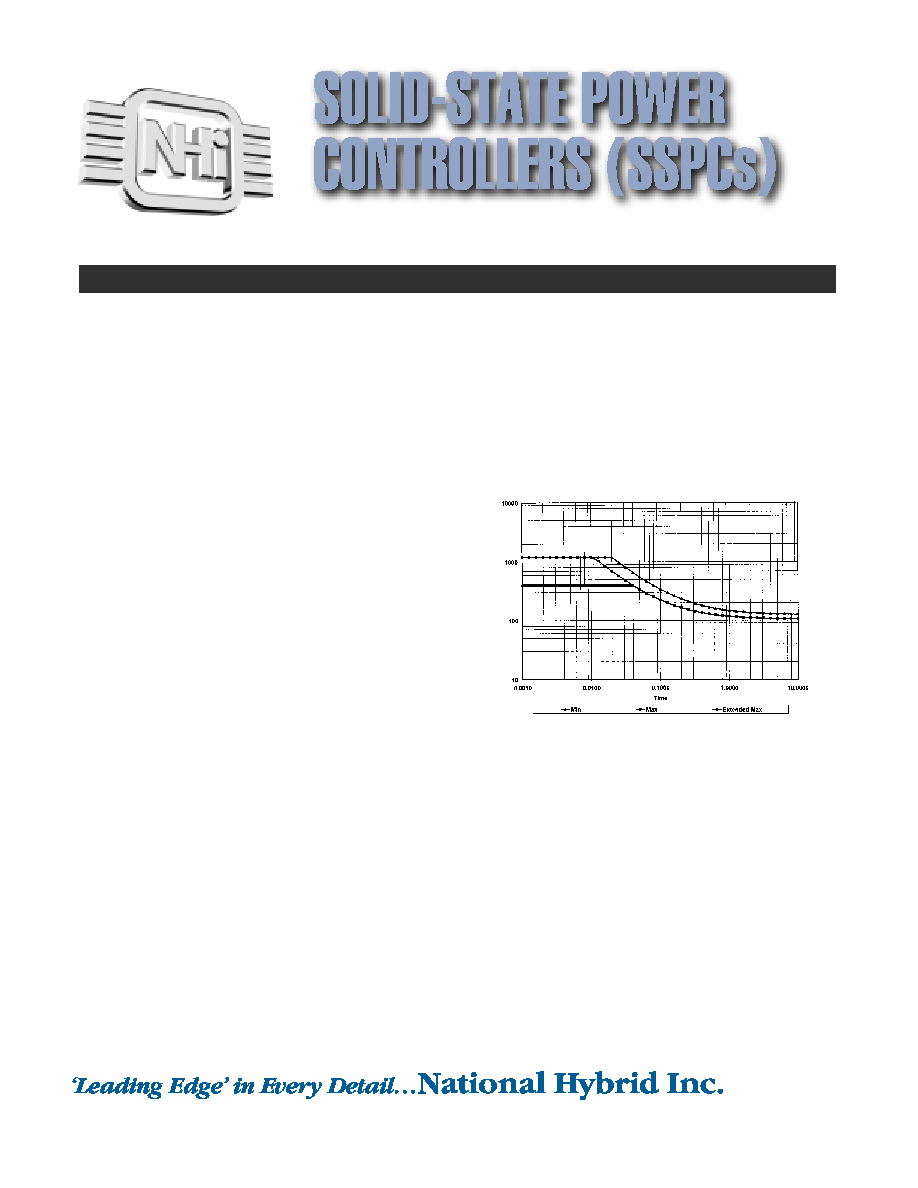
Referring to Figure #3, the heavy line shows the instant trip set to
400% of rated load. With decreasing current, the trip time increases.
At rated current, the unit will trip in 10 seconds. As a convenience
to our customers, NHI has designed its SSPC to allow external pro-
gramming of both the instant trip point and the trip time.
Figure 3--Typical I
2
T Curves
The Series 90000 package provides superior electrical performance and
lowest possible thermal resistance. Being a matched TCE system, the
package will withstand stringent environmental conditions. The flexibility
of the unique construction of the Series 90000 package allows for quick
and inexpensive custom configurations.
UNDERSTANDING SOLID-STATE POWER CONTROLLERS
I
2
t Trip Curve
% of Rated Load Current
SERIES 90000≠ 28 & 270-VDC, @10 & 20 AMPS
2200 Smithtown Ave., Ronkonkoma, NY 11779 ∑ 516-981-2400 ∑ FAX 516-981-8888 ∑ ISO 9001 & Mil-Std-1772 Certified & Qualified

∑ INSTANT TRIP PROTECTION--
Pin-programmable to
1,200% of rating.
Series 90000 SSPCs incorporate a programmable instant trip
feature. If the load current exceeds 400% of nominal rating, the
unit will trip in less than 25µ seconds.*
∑ INTERNAL THERMAL OVERLOAD PROTECTION
Series 90000 SSPCs contain built-in thermal overload protection.
The temperature of the switching elements is constantly moni-
tored. If their temperature exceeds a safe limit, the unit will turn
off and report an "over temperature" fault on its status outputs.
Restart is automatic when the unit cools down approximately
15∞C. For certain applications involving "battle override" require-
ments, the unit can be supplied such that an over-temperature
condition is reported on the status output, without protecting
itself by turning off.
∑ OPTICALLY ISOLATED CONTROL/STATUS CIRCUITRY
Series 90000 SSPCs utilize optical couplers for the control and
status reporting functions, ensuring complete isolation of these
"TTL"-compatible functions from the power line. The control
input is a diode-protected schmitt trigger gate for maximum noise
immunity. The status outputs are "HC" CMOS compatible and
can sink or source a minimum of 4 mA.
* Programmable to 800% for 270V, 1200% for 28V, by the addi-
tion of an external resistor.
∑ I
2
T PROTECTION--
Pin-programmable to 30% of rating.
Series 90000 SSPCs feature programmable, I
2
T trip characteristics.
This provides a relatively long (many seconds) trip time for mod-
est overloads, while severe overloads will trip in milliseconds. By
the addition of an external resistor, the actual trip point can be
lowered to as low as 30% of its nominal rating. This allows a sin-
gle type to be utilized in multiple applications, reducing inventory
and costs.
∑ MIL-STD-704 COMPLIANT
NHi's SSPCs are compliant to the surge and transient require-
ments of MIL-STD-704. The off-state voltage blocking rating
between the power and control/status pins is 100 VDC, with
500V minimum isolation for the 28V models. The 270V models
exhibit 600VDC voltage blocking with a minimum of 1000V isolation.
∑ LOW LOSS--
Forward voltage drop as low as 0.1 V on 28 VDC
devices. Power MOSFETs provide low ON resistance. The 270
VDC units use low Vsat IGBTs (<1.2 Volts max.) as the pass
elements. The unique construction of Series 90000 SSPCs utilizes
the high-current input/output tabs as the mounting mechanism,
and the heat sink for the high-power switching elements. The
direct metallurgical bond between the switching elements and
these tabs ensures extremely low electrical ON resistance and a
minimum ÿjc for the switching elements.
Set to trip at 8 Amps and Instant trip at 80 Amps.
This is a reasonable selection for operating a 200W lamp load.
TYPICAL APPLICATIONS
2200 Smithtown Ave., Ronkonkoma, NY 11779 ∑ 516-981-2400 ∑ FAX 516-981-8888 ∑ ISO 9001 & Mil-Std-1772 Certified & Qualified
SERIES 90000≠ 28 & 270-VDC, @10 & 20 AMPS

COMMAND
CONTROL
STATUS
STATUS OUTPUT
SSPC
INPUT
S1
S2
STATUS
1
OFF
0
0
0
OFF
Normal Off
2
OFF
0
0
1
OFF
Over Temp
3
OFF
0
1
0
OFF
SSPC Fail
4
OFF
0
1
1
ON
SSPC Fail
5
ON
1
0
0
ON
Normal On
6
ON
1
0
1
OFF
Over Temp
7
ON
1
1
0
OFF
Tripped
8
ON
1
1
1
OFF
SSPC Fail/
No line voltage
∑ Voltage Transients
In any circuit configuration, it is necessary to guard against voltage
transients during Off switching of SSPCs. NHI SSPCs are
equipped with an internal shunt diode for negative transients on
the load side. On the Line side, the user is required to place a
transient voltage suppressor. The transients at this terminal are
positive and add to the line voltage. To prevent voltage break-
down of the switch elements, a Transorb of proper voltage and
energy rating is utilized. Voltages on 28 VDC units should never
exceed 100 VDC, and 600 VDC on 270 VDC units. Transorb
should be installed as close as possible to the SSPC. Any induc-
tance between the two compromises Transorb effectiveness.
∑ Current Transients
During `turn on', capacitive loads cause high surge currents
limited only by wire impedances. If the capacitance value is too
great, the instant trip circuit might trip the SSPC. Soft turn-on of
the MOSFET or IGBT reduces the effect of this condition.
However, the design engineer shall carefully examine his system
to ensure that high capacitive loads are minimized and that there
is a reasonable resistance in the wiring to limit high surge currents.
SYMBOL
PARAMETER
MIN
TYPICAL
MAX
UNITS
V
ih
Control Input High
3.15
Volts
V
iL
Control Input Low
0.9
Volts
V
OH
Output High
4.0
Volts
V
OL
Output Low
0.4
Volts
I
dd
Supply Current
25
35
mA
OPERATING CONSIDERATIONS
Table 2 -- I/O Specifications
Table 3 -- Truth Table
TTL/CMOS - compatible status lines report SSPC operating conditions to the system.
Eight different states are possible, as described above.
2200 Smithtown Ave., Ronkonkoma, NY 11779 ∑ 516-981-2400 ∑ FAX 516-981-8888 ∑ ISO 9001 & Mil-Std-1772 Certified & Qualified
SERIES 90000≠ 28 & 270-VDC, @10 & 20 AMPS

SYMBOL
PARAMETER
MIN
TYPICAL
MAX
UNITS
I
L
Instantaneous Trip Current
40
120
Amps
(90270-XX)
40
80
Amps
R
ON
On Resistance
90028-10
.025
.03
Ohms
90028-20
.015
.02
Fwd Drop
Forward Drop 90270-XX
1.0
1.2
Volts
I
Leak
Leakage Current
200
uAmps
V
O off
V out when off (No Load)
1
Volts
C
IO
Line to Load Capacitance
1000
pFarads
t
on
Delay to t
on
1
mSecs
t
OFF
Delay to t
OFF
1
mSecs
0-jc
Thermal Resistance
0.25
∞C/Watts
t
r
Rise Time
0.6
1
mSecs
t
f
Fall Time
0.1
mSecs
Trip Time @ 200% of rated load
.2
Secs
Trip Time @ 300% of rated load
.09
Secs
Figure 1: Current Trip Selection
A resistor between pins 6 and 7 allows the user to set the trip point to any value
between 3 and 10 Amps. The chart shows the relationship between the resistor value
(R
ext
) and the trip current.
Figure 2: Instant Trip Selection
Leaving Pin 8 open sets trip to 40 Amps. Connecting it to Pin 6 sets it to 120 Amps.
(80 Amps for 270-Volt units.) Placing a resistor between pins 6 and 8 allows the user
to set the INSTANT trip point to any value between 40 and 120 Amps (40 and 80
Amps for 270-Volt Units). The chart shows the relationship between the resistor value
and the INSTANT trip current.
2200 Smithtown Ave., Ronkonkoma, NY 11779 ∑ 516-981-2400 ∑ FAX 516-981-8888 ∑ ISO 9001 & Mil-Std-1772 Certified & Qualified
SERIES 90000≠ 28 & 270-VDC, @10 & 20 AMPS