 | –≠–ª–µ–∫—Ç—Ä–æ–Ω–Ω—ã–π –∫–æ–º–ø–æ–Ω–µ–Ω—Ç: MCP2140 | –°–∫–∞—á–∞—Ç—å:  PDF PDF  ZIP ZIP |
2004 Microchip Technology Inc.
Preliminary
DS21894A-page 1
MCP2122
Features
∑ Pinout compatible with HSDL-7000
∑ Compliant with IrDA
Æ
Standard Physical Layer
Specification (version 1.3)
∑ UART to IrDA Standard Encoder/Decoder
- Interfaces with IrDA Standard Compliant
Transceiver
∑ Baud rates:
- Up to IrDA standard 115.2 Kbaud operation
∑ Transmit/Receive formats (bit width) supported:
- 1.63 µs
∑ Low-power mode (2 µA at 1.8V, +125∞C)
CMOS Technology
∑ Low-voltage operation
∑ Extended temperature range
∑ Low power consumption
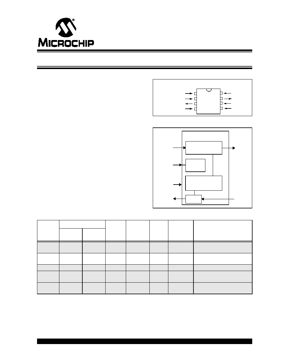
Package Types
Block Diagram
IrDA Family Selection
PDIP, SOIC
MCP2
122
V
SS
16XCLK
RESET
RXIR
TXIR
V
DD
TX
RX
1
2
3
4
8
7
6
5
Encode
Decode
TX
TXIR
RX
RXIR
RESET
MCP2122
Reset
Baud Rate
Generator
Logic
16XCLK
Device
Baud Rate
Encoder/
Decoder
Protocol
Layer
Handler
Clock
Source
Host UART
Baud Rate
Selection
Comment
Host
UART
IR
MCP2120 2400 -
312,500
(1)
2400 -
312,500
(1)
Yes
No
XTAL
HW/SW
MCP2122 2400 -
115,200
(1)
2400 -
312,500
(1)
Yes
No
16XCLK By 16XCLK Extended Temperature Range
(-40∞C to +125∞C)
MCP2140 9600
9600
Yes
IrCOMM
(3)
XTAL
None -Fixed
MCP2150 9600 -
115,200
(2)
9600 -
115,200
(2)
Yes
IrCOMM
(3)
XTAL
HW
Host UART easily interfaces to
a PC's serial port (DTE)
MCP2155 9600 -
115,200
(2)
9600 -
115,200
(2)
Yes
IrCOMM
(3)
XTAL
HW
Host UART easily interfaces to
a modem's serial port (DCE)
Note 1: The host UART and the IR operate at the same baud rates.
2: The host UART baud rate and the IR baud rates operate independent of each other.
3: Supports the 9-wire "cooked" service class of the IrCOMM Application Layer Protocol.
Infrared Encoder/Decoder

MCP2122
DS21894A-page 2
Preliminary
2004 Microchip Technology Inc.
NOTES:

2004 Microchip Technology Inc.
Preliminary
DS21894A-page 3
MCP2122
1.0
DEVICE OVERVIEW
The MCP2122 is a stand-alone IrDA standard encoder/
decoder device that is pinout-compatible with the
Agilent
Æ
HSDL-7000 Encoder/Decoder.
The MCP2122 has two interfaces: the host UART
interface and the IR interface (see Figure 1-1). The host
UART interfaces to the UART of the host controller. The
host controller is the device in the embedded system
that transmits and receives the data. The IR interface
connects to an infrared (IR) optical transceiver circuit,
which converts electrical pulses into IR light (encode)
and converts IR light into electrical pulses (decode).
This IR optical transceiver circuit could be either a stan-
dard infrared (IR) optical transceiver (such as a Vishay
Æ
TFDU 4100) or it could be implemented with discrete
components. For additional information, please refer to
Application Note 243, "Fundamentals of the Infrared
Physical Layer" (DS00243).
When the host controller transmits the UART format
data, the MCP2122 receives this UART data and
encodes (modulates) the data bit by bit. This encoded
data is then output as electrical pulses to the IR Trans-
ceiver. The IR transceiver will then convert these
electrical pulses to IR light pulses.
The IR Transceiver also receives IR light pulses (data),
which are outputted as electrical pulses. The MCP2122
decodes (demodulates) these electrical pulses, with
the data then transmitted by the MCP2122 UART. This
modulation and demodulation method is performed in
accordance with the IrDA standard.
Table 1-1 shows an overview of some of the device
features. Figure 1-1 shows a typical application block
diagram. Table 1-2 shows the pin definitions of the
MCP2122 in normal operation.
TABLE 1-1:
MCP2122 FEATURES
OVERVIEW
Infrared Technology Features:
∑ Universal standard for connecting portable
computing devices
∑ Easy, effortless implementation
∑ Economical alternative to other connectivity
solutions
∑ Reliable, high speed connection
∑ Safe to use in any environment; can even be used
during air travel
∑ Eliminates the hassle of cables
∑ Allows PC's and non-PC's to communicate to
each other
∑ Enhances mobility by allowing users to easily
connect
1.1
Applications
Some applications where an IR interface (MCP2122)
could be used include:
∑ Data Logging/Data Exchange
∑ System Setup
∑ System Diagnostic Read Out
∑ Manufacturing Configuration
∑ Host Controller Firmware Updates
∑ System Control
FIGURE 1-1:
SYSTEM BLOCK DIAGRAM
Features
MCP2122
Serial Communications:
UART, IR
Baud Rate Selection:
16XCLK
Low Power Mode:
Yes
Resets: (and Delays)
RESET pin (none)
Packages:
8-pin PDIP
8-pin SOIC
Encode
Decode
TX
TXIR
RX
RXIR
RESET
MCP2122
PICmicro
Æ
SO
SI
TFDU 4100
UAR
T
TXD
RXD
Reset
Logic
Clock
Logic
16XCLK
Clock
Host UART
Interface
IR
Interface
Host Controller
Protocol Handler
Optical
Transceiver
(I/O)
MCU

MCP2122
DS21894A-page 4
Preliminary
2004 Microchip Technology Inc.
TABLE 1-2:
PIN DESCRIPTION
Pin Name
Pin Number
Pin
Type
Buffer
Type
PDIP
SOIC
Description
16XCLK
1
1
I
ST
16x external clock source input
TX
2
2
I
ST
Asynchronous receive from host controller UART
RX
3
3
O
--
Asynchronous transmit to host controller UART
V
SS
4
4
--
P
Ground reference for logic and I/O pins
RESET
5
5
I
ST
Resets the Device
H = Normal Operation
L = Device in Reset
RXIR
6
6
I
ST
Asynchronous receive from infrared transceiver
TXIR
7
7
O
--
Asynchronous transmit to infrared transceiver
V
DD
8
8
--
P
Positive supply for logic and I/O pins
Legend: ST = Schmitt Trigger input with CMOS levels
I = Input
O = Output
P = Power

2004 Microchip Technology Inc.
Preliminary
DS21894A-page 5
MCP2122
2.0
DEVICE OPERATION
The MCP2122 is a low-cost infrared encoder/decoder.
The baud rate is the same for the host UART and IR
interfaces and is determined by the frequency of the
16XCLK signal, with a maximum baud rate of
115.2 Kbaud.
The MCP2122 is made up of these functional modules:
∑ Clock Driver (16XCLK)
∑ Reset
∑ IR Encoder/Decoder
- IrDA Standard Encoder
- IrDA Standard Decoder
The 16XCLK circuit allows a clock input to provide the
device clock.
The Reset circuit supports an external reset signal.
The IR Encoder logic takes a data bit and converts it to
the IrDA signal according to the IrDA Standard Physical
Layer specification, while the IR Decoder logic takes
the IrDA standard signal and converts it to 8-bit data
bytes.
2.1
Power-up
As the device is powered up, there will be a voltage
range where the device will not operate properly. The
device should be reset once the device has entered the
normal operating range (from an out-of-voltage
condition). The RESET pin may then be forced high.
Other device operating parameters (such as frequency,
temperature, etc.) must also be within their operating
ranges when the device exits reset. Otherwise, the
device may not function as desired.
2.2
Device Reset
The MCP2122 is forced into the known state (RESET)
when the RESET pin is in the low state. Once the
RESET pin is brought to a high state, the device begins
normal operation (if the device operating parameters
are met). Table 2-1 shows the states of the output pins
while the device is in reset (RESET = Low). Table 2-2
shows the state of the output pins once the device exits
reset, RESET = L
H (device in Normal Operation
mode).
The MCP2122 has a RESET noise filter in the RESET
input signal path. The filter will detect and ignore small
pulses.
Using the RESET pin to enter a low-power state is
discussed in
Section 2.9 "Minimizing Power"
.
TABLE 2-1:
DEFAULT OUTPUT PIN
STATES IN DEVICE RESET
TABLE 2-2:
DEFAULT OUTPUT PIN
STATES AFTER DEVICE
RESET (RESET = L
H)
2.3
Decoupling
It is highly recommended that the MCP2122 have a
decoupling capacitor (C
BYP
). A 0.01 µF capacitor is
recommended as a starting value, but evaluation of the
best value for your circuit/layout should be done. Place
this decoupling capacitor (C
BYP
) as close to the
MCP2122 as possible ( see Figure 2-1).
FIGURE 2-1:
DEVICE DECOUPLING
Input Pin
Output Pin
State
Comments
Name
State
RX
TXIR
RESET
L
H
L
Device in Reset mode
Input Pin
Output Pin
State
Comments
Name State
RX
TXIR
TX
L
--
L
H
L
After 7 - 8 16XCLK
pulses, the TXIR pin
will pulse high.
H
--
L
RXIR
L
H
L
--
After 4 16XCLK pulses,
RX = L.
H
H
--
V
DD
(bypass
capacitor)
MCP2122
V
DD
RESET
V
SS
16XCLK
TX
RX
TXIR
RXIR
C
BYP