NJU3501
Q˝
TERMINAL DESCRIPTION 1
No.
SYMBOL
INPUT/OUTPUT
F U N C T I O N
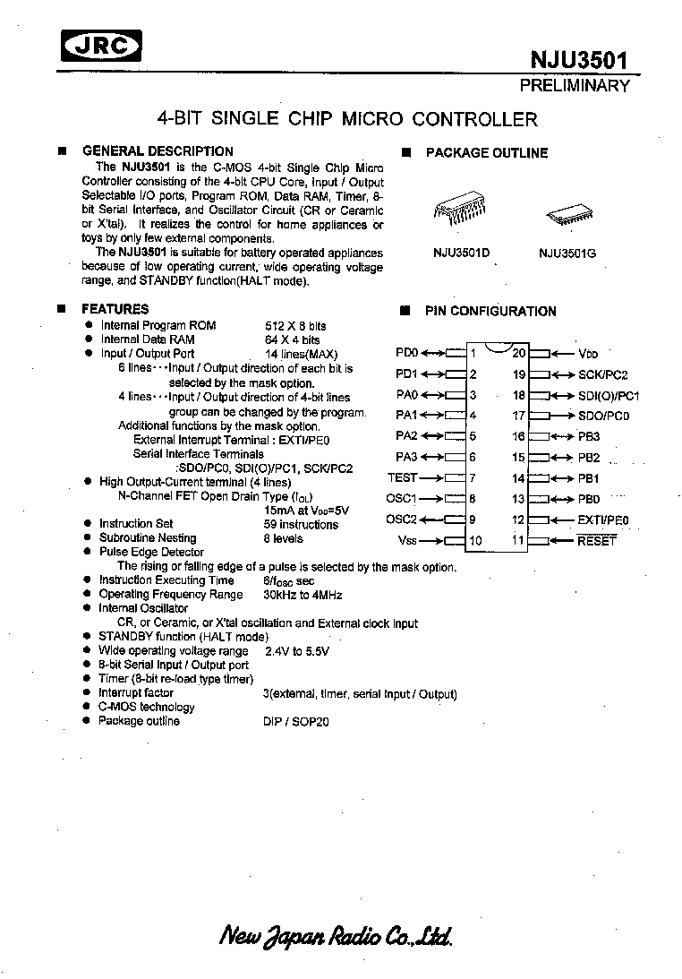
1
2
PD0
PD1
INPUT/OUTPUT
INPUT/OUTPUT
2-bit Input / Output PORTD.
Selects a terminal circuit for each port from follows by the
mask option.
x
C-MOS Schmitt Trigger Input Terminal with
Pull-up Resistance(IB)
x
C-MOS Schmitt Trigger Input terminal(ID)
x
C-MOS Output Terminal(OB)
When the ports are selected as the input terminal, PD0
operates also as RESTART signal input terminal to return
from STANDBY mode, and PD1 operates also as the Edge
Detector Terminal.
3
4
5
6
PA0
PA1
PA2
PA3
INPUT/OUTPUT
INPUT/OUTPUT
INPUT/OUTPUT
INPUT/OUTPUT
4-bit Input / Output PORTA.
Selects a terminal circuit for each port from follows by the
mask option.
x
C-MOS Input Terminal with Pull-up Resistance(IA)
x
C-MOS Input Terminal(IC)
x
C-MOS Output Terminal(OB)
7
TEST INPUT
Maker Testing Terminal with Pull-down Resistance
The terminal is recommended to connect to GND.
8
9
OSC1
OSC2
INPUT
OUTPUT
Internal Oscillator Terminals.
Connects a device selected from the ceramic or the crystal
resonator, or the resistor, to these terminals for the internal
oscillator.
In the external clock operation, OSC1 is the external clock
input terminal and OSC2 is normally open terminal.
10
V
SS
≠
Power Source (0V)
11
RESET
INPUT
RESET Terminal.
When the low level input-signal, the system is initialized.
12
EXTI / PE0
INPUT
1-bit Input PORTE.
Selects a function of either 1) or 2) for PORTE by the mask
option.
1) External Interrupt Input Terminal with Pull-up Resistance.
:EXTI
2) 1-bit Input Terminals as PORTE.
Selects a terminal circuit for each port from follows by the
mask option.
x
C-MOS Schmitt Trigger Input Terminal with
Pull-up Resistance(IB)
x
C-MOS Schmitt Trigger Input Terminal(ID)
13
14
15
16
PB0
PB1
PB2
PB3
INOUT
INOUT
INOUT
INOUT
4-bit Programmable Input / Output PORTB
These 4-bit terminals' direction can be changed by the
program as 4-Input or 4-Output.
Use of Pull-up resistance is in accordance with the mask
option.
x
as Input : C-MOS Input Terminals
x
as Output : Nch-FET Open-Drain Output Terminals
Note )
INPUT/OUTPUT : Input or Output is selected by the mask option.
INOUT
: Input or Output is changed by the program.
NJU3501
n
TERMINAL DESCRIPTION 2
No.
SYMBOL
INPUT/OUTPUT
F U N C T I O N
17
18
19
SDO / PC0
SDI(O) / PC1
SCK / PC2
SDO :OUTPUT
SDI(O) :INOUT
SCK :INOUT
PC0 to PC2 :
INPUT/OUTPUT
3-bit Input / Output PORTC.
Selects a function of either 1) or 2) for PORTC by the mask
option.
1) Serial Interface Function.
Serial Data Output Terminal : SDO
Serial Data Input-Output Terminal with Pull-up
Resistance : SDI(O)
Serial Clock Input or Output Terminal with Pull-up
Resistance : SCK
2) 3-bit Input / Output Terminal PORTC.
Selects a terminal circuit for each port from follows by the
mask option.
x
C-MOS Input Terminal with Pull-up Resistance(IA)
x
C-MOS Input Terminal(IC)
x
C-MOS Output Terminal(OB)
20
V
DD
≠
Power Source (2.4V to 5.5V)
Note )
INPUT/OUTPUT : Input or Output is selected by the mask option.
INOUT
: Input or Output is changed by the program.