Ver.4
NJW1303
- 1 -
SYNCHRONOUS SEPARATOR WITH COUNT DOWN
T
T
T
T
GENERAL DESCRIPTION
T
T
T
T
PACKAGE OUTLINE
The NJW1303 is a synchronous separator performs
Horizontal and Vertical synchronous signal from composit video
signals. It contains count down circuit for H,V keeping high sync
separation in the weak signal. It is suitable for car navigation and
LCD TV.
T
T
T
T
FEATURES
�Operating Voltage V
+
=2.7V to 5.3V
�Operating Current 5mA typ. at V
+
=5V
�Output for HD,VD,C sync
�unnecessary adjustment of oscillation frequency for internal count down circuit
�Internal BGP
�Bi-CMOS Technology
�Package Outline SSOP14
T
T
T
T
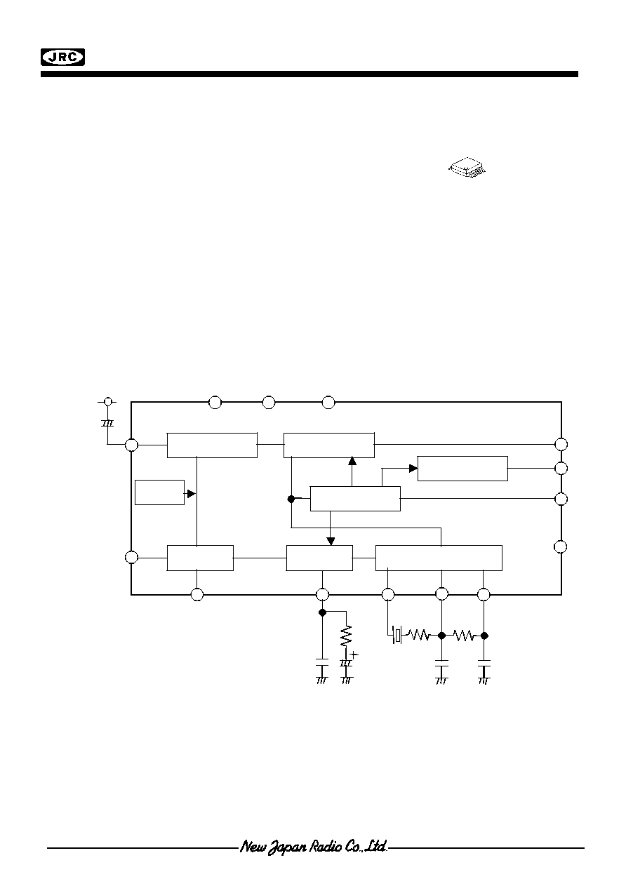
PIN FUNCTION, BLOCK DIAGLAM
32fH VCO
V count down
Phase Det
V Sync Sep
VS
Sync IN
GND DIGREF
C Sync OUT
VD
HD
LPF
H count down
BGP Generator
BGP
Vcc
Vcc
VCO Out
VCO
Filter 2
VCO
Filter 1
14
12
+
+
+
+
Sync Sep
Reg
1
2
9
10
11
3 13
6
4
8
5
SW
7
NJW1303V
NJW1303
Ver.4
- 2 -
T
T
T
T
ABSOLUTE MAXIMUM RATINGS (Ta=25
�
�
�
�
C)
PARAMETER SYMBOL
RATINGS
UNIT
Supply Voltage
V
+
8.0 V
Power Dissipation
P
D
300 mW
Operating Temperature Range
Topr
-40 to +85
�
C
Storage Temperature
Tstg
-40 to +125
�
C
T
T
T
T
RECOMMENDED OPERATING CONDITION
PARAMETER SYMBOL
RATINGS
UNIT
Supply Voltage
Vopr
2.7 to 5.3
V
T
T
T
T
ELECTRICAL CHARACTERISTICS
( V
+
=5V, Ta=25
�
C)
PARAMETER SYMBOL
TEST
CONDITION
MIN.
TYP.
MAX.
UNIT
Operating Current
I
CC
No input signal
3.3
5.0
7.5
mA
AFC Free Run Frequency
f
OH
Measure the Input connect to GND
under 300ohm
15.654 15.734 15.814
kHz
f
HL
1
Miss lock to high frequency
+600
+700
-
AFC Lock Range
f
HL
2
Miss lock to Low frequency
-
-700
-600
Hz
f
HP
1
Capture from high frequency
+600
+700
-
AFC Capture Range
f
HP
2
Capture from Low frequency
-
-700
-600
Hz
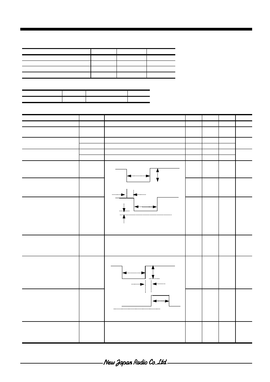
Horizontal Output
Pulse Width
PwHD
3.5 3.9 4.3 us
Horizontal Output Delay
TpDH
0.48
0.64
0.8
us
Horizontal Output
Saturation Level
VoLH
-0.2 0.1 0.3 V
Horizontal AFC Keep
Limit Input
V
IN
GM
Input is Color Bar of 1Vpp,and
Horizontal signal of 4.8 uS pulth width.
ATT less of miss lock Sync at valuable
of input signal level.
- - -20
dB
BGP Pulse Width
PwGP
3.1
3.6
4.1
us
BGP Delay
TpDG
0.35 0.6 0.85
us
BGP Limit Input
V
MIN
BGP
Input is Color Bar of 1Vpp,and
Horizontal signal of 4.8 uS pulth width.
ATT less of changeable BGP output at
less of input signal level.
- - -17
dB
0V
4.8us
286mVpp
Input Signal
TpDG
PwGP
Output Signal
*point1
Input Signal
4.8us
286mVpp
TpDH
PwHD
Output Signal
VoLH
0V
*point1
Ver.4
NJW1303
- 3 -
T
ELECTRICAL CHARACTERISTICS
( V
+
=5V, Ta=25
�
C)
PARAMETER SYMBOLS
TEST
CONDITIONS
MIN.
TYP.
MAX.
UNIT
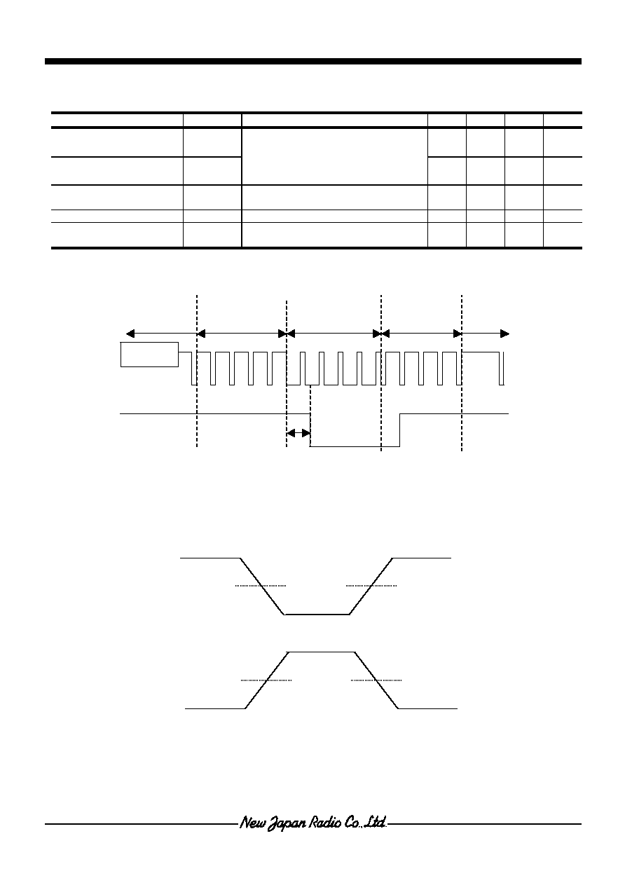
Vertical Output
Pulse Width
PwVD 2.5
3.0
3.5
H
Vertical Output Delay
TpVD
*point
0.47 0.66 0.85
H
Vertical Output
Saturation Level
V
L
VD
Low level of Vertical output
-
0.2
0.5
V
C.SYNC Output Delay
TpCS
0.32
0.5
0.64
us
C.SYNC Output
Saturation Voltage
V
L
CS
- 0.2 0.5 V
*point
*When measure of pulse timing
50%
50%
50%
50%
Signal
Equivalent Palse
VD Output
Input Signal
TpVD
Vertical Sync.Pulse
Equivalent Palse
NJW1303
Ver.4
- 4 -
T
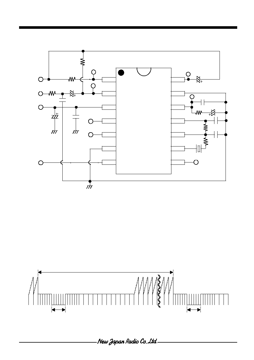
TEST CIRCUIT
*1: CSBLA503KE5ZF10 at MURATA
*2: NTSC/PAL SW
NTSC : GND
PAL :Vcc,and 9 to10pin is 360 ohm, 10 to 11pin is 2 k ohm
s
s
s
s
APPLICATION NOTES
�
The ratio of the vertical synchronous pulse term and the vertical synchronous signal cycle
Please adjust following expression.
The vertical synchronous signal cycle / The vertical synchronous pulse term
75 (see following figure)
�
The pulse width of horizontal synchronous signal shall be set 3.7 to 5.7
�
.s
1k
TPV
(VCC)
1
2
3
4
5
6
7
8
9
10
11
12
13
14
*1
390
1.8k
3k
4.7uF
15000pF
1uF
1uF
150pF
1000pF
CSYNCOUT
SYNCIN
VCC
VD
HD
DIGREF
SW
VS
GND
LPF
VCOFIL1
VCOFIL2
VCOOUT
BGP
330pF
360
910k
*2
100uF
68000pF
Vertical Synchronous Signal cycle
Vertical Synchronous Pulse term
Vertical Synchronous Pulse term
Ver.4
NJW1303
- 5 -
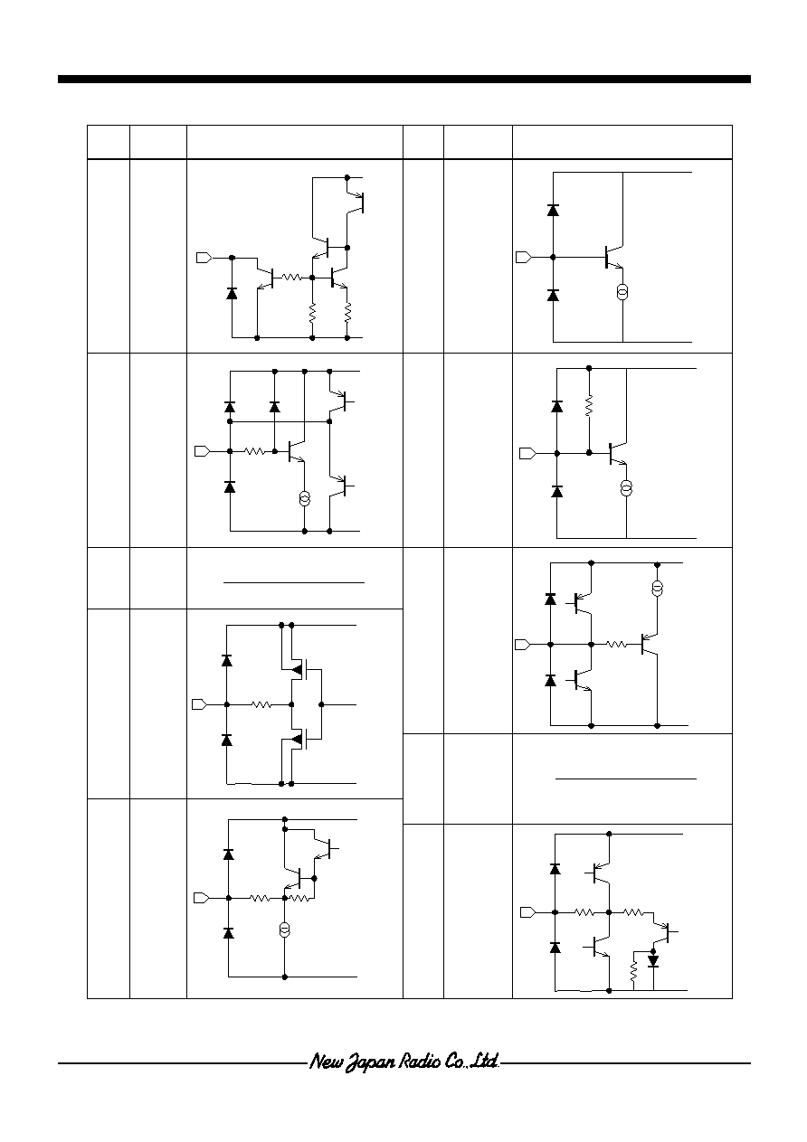
T EQUIVALENT CIRCUIT
No.
NAME
INSIDE EQUIVALENT CIRCUIT
No.
NAME
INSIDE EQUIVALENT CIRCUIT
1
Csync.
Out
10
VCO
Filter 2
2
Sync.
In
11
VCO
Filter 1
3 Vcc
12 LPF
4
5
7
8
VD
HD
SW
BGP
6
13
DIGREF
GND
9
VCO
Out
14 VS
VCC
GND
3k
3k
20k
VCC
GND
200
VCC
GND
VCC
GND
10k
VCC
GND
DIGREF
VCC
200
VCC
200
GND
VCC
GND
200