
NJW4120
- 1 -
Ver.2005-03-09
Lithium-ion Battery Charger Controller IC with Timer
GENERAL DESCRIPTION
PACKAGE OUTLINE
FEATURES
Charge Control Feedback by Photocoupler
Adjustable Charge Voltage
Adjustable Pre-Charge and Full Charge Current
Temperature Monitor
Over Charge Timer
Internal Re-Charge function
Delay timers and Hysteresis inputs for high noise immunity
Over Discharge Battery Detect
Over Voltage Protection
Bi-CMOS Technology
Package Outline
NJW4120M : DMP20
NJW4120V :
SSOP20
PIN CONFIGURATION
NJW4120 is a 1-cell and 2-cell lithium ion battery charge control IC
with a built-in AC-DC secondary side control feature. Using a
photocoupler to directly feed back optimum charging voltage and
current information to the primary side, it increases energy
efficiency, makes possible a smaller charger, and conserves
energy. Charging current can be freely set and therefore it is
possible to optimize charging according to battery capacity.
As safety features it has over voltage, over discharge, temperature
detection, and a charge over timer. Also, the adaptor and the
charge control circuit are mounted on one chip.
NJW4120M NJW4120V
1
4
3
2
20
17
18
19
5
6
7
10
8
9
14
11
12
13
15
16
P-CHG
NFB
TX-SW
GND
PC
ADP
LED-G
LED-R
C1
C2
CHG-SW
TL
TH
TDET
V
+
VREF
VS
CS2
CS1
Q-CHG
NJW4120M
NJW4120V

NJW4120
- 2 -
Ver.2005-03-09
ABSOLUTE MAXIMUM RATINGS (Ta=25�C)
PARAMETER SYMBOL
MAXIMUM
RATINGS
UNIT
Operating Voltage
V
+
+15 V
C1 Pin Voltage
V
C1
+5 V
C2 Pin Voltage
V
C2
+5 V
TDET Pin Voltage
V
TDET
+5 V
TX-SW Pin Output Current
I
SINK-SW
50 mA
PC Pin Output Current
I
SINK-PC
50 mA
LED-G Pin Output Current
I
SINK-G
20 mA
LED-R Pin Output Current
I
SINK-R
20 mA
Power Dissipation
P
D
DMP20 :300
SSOP20 :300
mW
Operating Temperature Range
T
opr
-20~+85
�
C
Storage Temperature Range
T
stg
-40~+125
�
C
ELECTRICAL CHARACTERISTICS (V
+
=5V, Ta=25
�
C)
PARAMETER SYMBOL TEST
CONDITION MIN.
TYP.
MAX.
UNIT
General Characteristics
Operating Voltage
V
OP
2.7 � 14 V
Operating Current
I
CC
CHG-SW:
OPEN
� 2 3
mA
Under Voltage Lockout Block
ON Threshold Voltage
V
T-ON
2.2 2.4 2.6 V
OFF Threshold Voltage
V
T-OFF
2.0 2.2 2.4 V
Hysteresis Voltage
V
HYS
100 200 300 mV
Reference Voltage Block
Reference Voltage
V
REF
I
REF
=0mA 1.228
1.24
1.253
V
Load Regulation
V
REF
I
REF
=0mA~1mA �
�
10
mV
Voltage Detection Block
Quick Charge Detection Voltage
V
Q-CHG
VS: L
H
V
BAT
x 0.71
V
BAT
x 0.73
V
BAT
x 0.75
V
Re-Charge Detection Voltage
V
R-CHG
VS: H
L
V
BAT
x 0.94
V
BAT
x 0.95
V
BAT
x 0.96
V
Over Voltage Detection Voltage
V
OV
VS: L
H
V
BAT
x 1.015
V
BAT
x 1.025
V
BAT
x 1.035
V
Charge Control Block
Reference Voltage
V
REF-CV
VS
Pin
2.08 2.1 2.12 V
Adaptor Control Block
Reference Voltage
V
REF-ADP
1.228 1.24 1.253
V
VS Pin Input Bias Current
I
VS
VS=2.1V
� 50 500 nA
Battery Connected
Detection Voltage
V
T-TDET
TDET
Pin
� 1.15 �
V
Low Voltage Detection (2mA Charge) Block
Charge Current
I
CHG1
VS=1V
1 2 3
mA
Low Voltage Detection Voltage
V
LV
VS: L
H
V
BAT
x 0.505
V
BAT
x 0.525
V
BAT
x 0.545
V

NJW4120
- 3 -
Ver.2005-03-09
ELECTRICAL CHARACTERISTICS (V
+
=5V, Ta=25
�
C)
PARAMETER SYMBOL TEST
CONDITION MIN.
TYP.
MAX.
UNIT
Current Detection Block
Pre-Charge /Quick Charge Block
Voltage Gain
A
V1
CS1=3.8V,
CS2=3.6V
11.5 12 12.5 dB
Full Charge Detection Voltage
V
F
CS2=4.2V,
VS=2.1V
8 12 16 mV
CS1 Pin Input Bias Current
I
CS1
CS1=4.2V
�
10 500 nA
CS2 Pin Input Bias Current
I
CS2
CS2=4.2V
�
10 500 nA
Photocoupler Out Block
Photocoupler Out
Saturation Voltage
V
OL-PC
I
SINK
=20mA �
0.2
0.5
V
PC Pin Leak Current
I
LEAK-PC
V
+
=14V
� � 1
�
A
TX-SW Out Block
TX-SW Out Saturation Voltage
V
OL-SW
I
SINK
=20mA �
0.2
0.5
V
TX-SW Pin Leak Current
I
LEAK-SW
V
+
=14V
� � 1
�
A
LED Out Block
LED-G Pin Saturation Voltage
V
OL-G
I
SINK
=10mA �
0.2
0.5
V
LED-G Pin Leak Current
I
LEAK-G
V
+
=14V
� � 1
�
A
LED-R Pin Saturation Voltage
V
OL-R
I
SINK
=10mA �
0.2
0.5
V
LED-R Pin Leak Current
I
LEAK-R
V
+
=14V
� � 1
�
A
Timer Block
OSC1 Timer Error Time
T1 -10
�
+10
%
OSC2 Timer Error Time
T2
C1=C2=0.01
�
F external
Not including external deviation
-10 � +10 %
CHG-SW Block
ON Threshold Voltage
V
SW-ON
�
�
0.25 V
OFF Threshold Voltage
V
SW-OFF
1
�
�
V
Pull-up Resistance
R
PULL-UP
300 500 700 k

NJW4120
- 4 -
Ver.2005-03-09
TYPICAL APPLICATION
Reference
Voltage 1
1.24V
Reference
Voltage 2
2.1V
V
REF1
V
REF2
OSC
1
OSC
2
Full
Charge
Timer
Pre-
Charge
Timer
CLK
Control
Logic
Start/Stop
Time Out
Low Voltage
Detection
Over Voltage
Detection
Re-Charge
Quick Charge
Full Charge
Detection
6dB
CVCC-ON
V
REF2
12dB
P
r
e-
C
har
ge
Contr
o
l
Q
u
i
c
k
C
h
ar
ge
Contr
o
l
CVCC-ON
Start/Stop
Time Out
V
BAT
x 1.025
Charge
-ON
V
BAT
x 0.525
V
BAT
x 0.95
V
BAT
x 0.73
Quick/
Pre-Charge
CVCC-ON
CS1 pin
2mA
Charge
Charge
ON/OFF
Battery
Voltage
Detection
R
P1
R
P2
R
Q1
R
Q2
Q-CHG
P-CHG
V
REF
PC
NFB
CS1
R
B1
R
B2
VS
Rcs
CS2
TX-SW
C1
C2
GND
V
REF
V
+
Input
GND
CVCC-ON
V
REF1
CVCC-ON
PC
ADP
1-cell:
R
B1
= R
B2
2-cell:
R
B1
= 3xR
B2
Adaptor Output
R
A1
R
A2
LED-G
LED-R
LED-G
LED-R
R
PULL-UP
V
+
V
+
CHG-SW
Low Temperature
Detection
High Temperature
Detection
Battery Connected
Detection
UVLO
TDET
TH
TL
Lithium Ion Battery
V
REF

NJW4120
- 5 -
Ver.2005-03-09
PIN CONFIGULATION
Pin No.
Pin Name
Function
1
P-CHG
Pre-Charge Current Setting
2 NFB
Current-Regulation-Loop
Compensation
3 TX-SW
Switch
Transistor
connection
4 GND
GND
5
PC
Photocoupler connection for the first side feedback
6
ADP
Adaptor Control Voltage Setting
7 LED-G
LED
Output
8 LED-R
LED
Output
9
C1
Pre-Charge Timer, 2mA Charge Timer, LED Blinking Cycle, Delay Time Setting
10 C2
Quick
Timer
Setting
11
CHG-SW
Charge ON/OFF Control
12
TL
Batteries Thermal (High Temperature) Setting
13
TH
Batteries Thermal (Low Temperature) Setting
14
TDET
Battery Temperature Detection, Battery Connected Detection
15 V
+
Operating
Voltage
16 VREF
Reference
Voltage
Output
17
VS
Battery Voltage Detection
18
CS2
Charge Current Detection 2
19
CS1
Charge Current Detection 1
20
Q-CHG
Quick Charge Current Setting
CHARGE VOLTAGE / CURRENT for RESISTANCE SETTING
Parameter
Calculation formula
Examples of calculation
Adaptor Output Voltage
V
ADP
=
2
A
2
A
1
A
R
R
R
+
x V
REF-ADP (1.24V)
5.0V 10V
Charge Control Voltage
V
BAT
=
2
B
2
B
1
B
R
R
R
+
x V
REF-CV (2.1V)
4.2V 8.4V
Low Voltage Detection
Voltage
V
BAT
x 0.525
2.21V
4.41V
Quick Charge Start Voltage
V
BAT
x 0.73
3.07 V
6.13 V
Re-Charge Detection Voltage
V
BAT
x 0.95
3.99 V
7.98 V
Over Voltage Detection
Voltage
V
BAT
x 1.025
4.305 V
8.61 V
Pre-Charge Current
I
P-CHG
= (
2
P
1
P
2
P
R
R
R
+
x V
REF (1.24V)
/ 4) / R
CS
(at. R
P1
:232k, R
P2
:16k, R
CS
=0.2)
100mA
Quick Charge Current
I
Q-CHG
= (
2
Q
1
Q
2
Q
R
R
R
+
x V
REF (1.24V)
/ 4) / R
CS
(at. R
Q1
:128k, R
Q2
:120k, R
CS
=0.2)
750mA
Full Charge Current
I
F-CHG
= (96mV / 8) / R
CS
(at. R
CS
=0.2)
60mA

NJW4120
- 6 -
Ver.2005-03-09
TYPICAL CHARACTERISTICS
2.08
2.09
2.1
2.11
2.12
-50
-25
0
25
50
75
100 125
Ambient Temperature Ta (
o
C)
Re
f
e
r
e
nc
e
Vo
l
t
ag
e
V
RE
F
-
C
V
(V
)
Charge Control Block Reference Voltage
v.s Temperature (V
+
=5V, VS Pin)
1.23
1.235
1.24
1.245
1.25
-50
-25
0
25
50
75
100 125
Ambient Temperature
Ta (
o
C)
Ad
op
t
o
r
C
o
n
t
r
o
l
Bl
oc
k
Re
f
e
r
e
nc
e V
o
l
t
a
g
e
V
RE
F
-
A
D
P
(V
)
Adoptor Control Block Reference Voltage
vs. Temperature (V
+
=5V)
1.23
1.235
1.24
1.245
1.25
-50
-25
0
25
50
75
100 125
Ambient Temperature
Ta (
o
C)
R
e
fer
enc
e V
o
l
t
ag
e
V
RE
F
(V
)
Reference Voltage vs. Temperature
(V
+
=5V, I
REF
=0mA)
11.4
11.6
11.8
12
12.2
12.4
12.6
-50
-25
0
25
50
75
100 125
Ambient Temperature
Ta (
o
C)
P
r
e-
C
h
a
r
ge
/Q
u
i
c
k
Ch
ar
ge
Bl
o
c
k
V
o
l
t
ag
e G
a
i
n
A
V1
(dB
)
Pre-Charge/Quick Charge Block Voltage Gain
vs. Temperature (V
+
=5V, CS1=3.8V, CS2=3.6V)
0.2
0.3
0.4
0.5
0.6
0.7
0.8
-50
-25
0
25
50
75
100 125
Ambient Temperature
Ta (
o
C)
T
h
r
e
s
h
ol
d
Vo
l
t
ag
e
(
V
)
CHG-SW Block Threshold Voltage
vs. Temperature (V
+
=5V)
V
SW_OFF
V
SW_ON
0
0.5
1
1.5
2
2.5
3
-50
-25
0
25
50
75
100 125
Ambient Temperature
Ta (
o
C)
O
p
er
a
t
i
n
g
C
u
r
r
en
t
I
CC
(m
A
)
Operating Current vs. Temperature
(V
+
=5V, CHG-SW:OPEN)

NJW4120
- 7 -
Ver.2005-03-09
TYPICAL CHARACTERISTICS
0
0.1
0.2
0.3
0.4
0.5
0
10
20
30
40
50
TX-SW
PC
Sa
t
u
r
a
t
i
o
n
Vo
l
t
a
g
e
V
OL
-
C
N
T
(V
)
TX-SW,PC Pin Saturation Voltage vs. Sink Current
(V
+
=5V, Ta=25
o
C)
Sink Current I
SINK
(mA)
0
0.1
0.2
0.3
0.4
0.5
0
5
10
15
20
S
a
tur
a
ti
on
V
o
l
t
a
g
e
V
OL
(V
)
LED Pin Saturation Voltage vs. Sink Current
(V
+
=5V, Ta=25
o
C)
Sink Current I
SINK
(mA)
LED-R
LED-G
1
10
100
0.001
0.01
0.1
O
s
c
i
l
l
a
t
i
on C
y
c
l
e
O
S
C1
,
OS
C
2
(
m
s
)
Oscillation Cycle vs. Capacitance
(V
+
=5V, Ta=25
o
C)
Capacitance C1, C2 (
�
F)
6
7
8
9
10
11
12
13
14
-50
-25
0
25
50
75
100 125
Ambient Temperature
Ta (
o
C)
Os
c
i
ll
a
t
io
n
C
y
c
l
e
O
S
C1
,
O
S
C
2
(
m
s
)
Oscillation Cycle vs. Temperature
(V
+
=5V, C1=C2=0.01
�
F)
NJW4120
- 8 -
Ver.2005-03-09
Feature Description
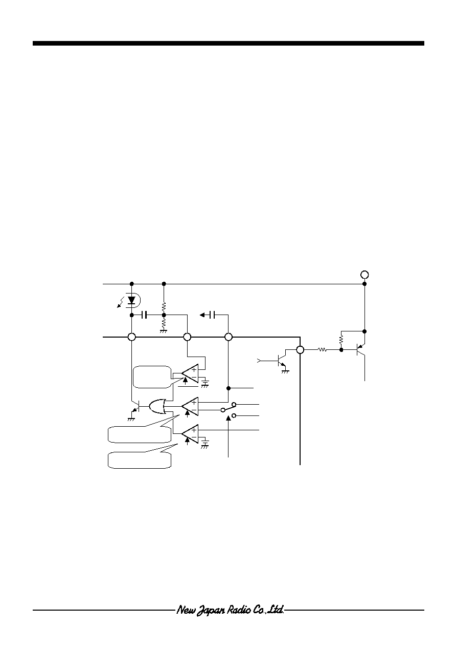
1. Photocoupler Feedback Unit (PC pin, CHG-SW pin, TX-SW pin)
NJW4120 feeds back voltage and current information that are required for battery charging via a photocoupler to the
primary side of the AC/DC converter, and controls AC/DC converter output. No special method is required if the
primary side of the AC/DC converter that is being controlled (whether self excited or externally excited) has circuitry
that takes into account the range of output voltage and current that is required for charge control.
It also incorporates an adaptor output mode, and extraction of any constant voltage output is possible. The following
will switch between charge control and adaptor output.
CHG-SW pin, and TDET pin battery set detection are both on: Charge control mode
Either CHG-SW pin, or TDET pin battery set detection is off: Adaptor output mode
However, if charging is prohibited due to over voltage detection, temperature detection, or the charge over timer, or
when there is 2mA of charge, the system will move to adaptor mode.
The unit that controls feedback to the photocoupler consists of the ADP voltage control, charge voltage control, and
charge current control amps. Each amp controls the photocoupler drive transistor via an OR circuit (Figure 1).
To VS pin
Adaptor output
R
A1
R
A2
PC ADP
NFB
PC
CVCC-ON
CVCC-ON
CVCC-ON
To P-CHG pin
To Q-CHG pin
To current detection
12dB amp
L
H
V
REF1
(1.24V)
Pre/Quick charge switch
V
REF2
(2.1V)
To AC/DC converter
primary side control
ADP voltage
control
Charge Current control
Charge voltage control
TX-SW
CVCC-ON
SW transistor
Figure 1 : Photocoupler Feedback Unit and SW Transistor

NJW4120
- 9 -
Ver.2005-03-09
Feature Description
(Continued)
Amp control and control of the SW transistor connected to the TX-SW pin are not the same in adapter output mode
and charge control mode.
1-1. Adapter output mode (ADP pin)
In adapter output mode, each of the circuits in the control unit will be in the following state.
ADP voltage control amp
ON
Charge voltage control amp
OFF
Charge current control amp
OFF
SW
transistor
OFF
To set the adapter output voltage, use the ADP pin's external resistors R
A1
, and R
A2
and the following formula.
V
ADP
=
2
A
2
A
1
A
R
R
R
+
x V
REF-ADP (1.24V)
In adapter output mode the SW transistor connected to the TX-SW pin will turn OFF, and charge to the battery will
be cut off. For this reason, take adapter output voltage from a power supply line that comes before the SW transistor.
1-2.Charge control mode
In the case of pre-charge and quick charge each of the circuits in the control unit will be in the following state.
ADP voltage control amp
OFF
Charge voltage control amp
ON
Charge current control amp
ON
SW
transistor
ON
However, when there is 2mA of charge, the system will operate in adapter output mode (SW transistor
OFF).
The SW transistor turns ON, and battery charging will be performed.
Charge voltage and charge current operations are described in "2. Voltage Detection Block", and "3. Current
Detection Block".

NJW4120
- 10 -
Ver.2005-03-09
2. Voltage Detection Block (VS pin)
The VS pin determines charge voltage, low voltage, over voltage, and re-charge voltage. Battery voltage conditions are
constantly monitored. (Figure 2)
2-1. Charge Voltage (VS pin)
Charge voltage V
BAT
is set using the VS pin external
resistors R
B1
and R
B2
and the following equation:
V
BAT
=
2
B
2
B
1
B
R
R
R
+
x V
REF-CV (2.1V)
Using the following settings makes it easy to support
applications for one or two cells: for one cell, R
B1
= R
B2
;
for two cells, R
B1
=3 x R
B2
.
If you use a high resistance, the VS pin's bias current will
cause incorrect values. Use as low a resistance as
possible.
2-2. Overcharge Detection Block (VS pin)
The overcharge detection block stops charging when a
high voltage is detected at the VS pin.
The overcharge detection voltage is obtained with the following equation:
V
OV
=V
BAT
�
1.025 (typ.)
When overcharge is detected, charging is prohibited and LED-R blinks. After that, charge will continue to be prohibited, even
after battery voltage drops to a normal value. Turning the power off to release UVLO, battery connection detection, or
CHG-SW switching will enable the charge sequence to restart.
2-3. Low Voltage Detection (2mA charge) Block (VS pin, CS1 pin)
The low voltage detection block detects an
over-discharged battery, or an open battery caused by
the battery protection circuit or the like. This will
determine a 2mA charge prior to pre-charging.
The low voltage detection voltage is obtained with the
following equation:
V
LV
=V
BAT
�
0.525 (typ.)
During a 2mA charge, the block monitors battery voltage
recovery while a steady 2mA current is output from the
CS1 pin. (Figure 3)
If voltage does not recover within a prescribed time, the
timer will prohibit 2mA charging. Turning the power off to
release UVLO, battery connection detection, or CHG-SW
switching will enable the charge sequence to restart.
2-4. Re-Charge Detection (VS pin)
When a fully charged battery is left for a long period of time, voltage will drop due to self-discharge. The re-charge detection
block detects a drop in voltage and re-charges the battery.
The re-charge detection voltage is obtained with the following equation.
V
R-CHG
=V
BAT
�
0.95 (typ.)
Low Voltage
Detection
12dB
CS1
R
B1
R
B2
VS
Rcs
CS2
To Charge
Output
Control Block
2mA Charge
Current
To Charge Current
Control Amp
2mA Charge
V
BAT
x 0.525
R
B1
R
B2
VS
To Charge
Control Block
To OR
Circuit
Charge Voltage
Control Amp
V
REF2
CVCC-ON
Low Voltage
Detection
Over Voltage
Detection
Recharge
Detection
Quick Charge
Detection
Battery
Voltage
Detection
1-cell
:
R
B1
= R
B2
2-cell
:
R
B1
= 3xR
B2
V
BAT
x 0.95
V
BAT
x 0.73
V
BAT
x 1.025
V
BAT
x 0.525
Figure 2. Voltage Detection Block Configuration
Figure 3. 2mA Charging Block

NJW4120
- 11 -
Ver.2005-03-09
FEATURE DESCRIPTION (CONTINUED)
3. Current Detection Block (CS1 pin, CS2 pin)
A current detection resistor R
CS
is inserted between pin CS1 and pin CS2 to monitor battery charge current.
The input voltage between pin CS1 and pin CS2 is amplified by the 12dB current detection amp and fed back to the charge
current control amp. (Figure 4)
3-1. Pre-Charge Current, Quick Charge Current (P-CHG pin, Q-CHG pin)
This will switch between charging with pre-charge current or quick charge current according to the level of the battery
voltage V
BAT
that is input from the VS pin.
V
BAT
x 0.525 to V
BAT
x 0.73
Pre-charge control
V
BAT
x 0.73 to V
BAT
Quick charge control
Pre-charge and quick charge current values are determined by the P-CHG pin and the Q-CHG pin voltage settings.
Settings are made according to the following formulae.
Pre-Charge Current Value
I
P-CHG
= (
2
P
1
P
2
P
R
R
R
+
x V
REF (1.24V)
/ 4) / R
CS
Quick Charge Current Value
I
Q-CHG
= (
2
Q
1
Q
2
Q
R
R
R
+
x V
REF (1.24V)
/ 4) / R
CS
3-2. Full Charge Detection (F-CHG pin)
Charge termination is determined by a set full
charge current
I
F-CHG
.
, which is determined by a
voltage setting on the F-CHG pin.
I
F-CHG
= (96mV/ 8) / R
CS
When charging is terminated, LED-G turns on,
and the sequence moves to the re-charge
detection operation.
Figure 4. Block for Controlling Pre-Charge, Quick Charge,
and Block for Detecting Full Charge.
To OR
Circuit
Quick Charge
Detection
Full Charge
Detection
6dB
CVCC-ON
12dB
Pr
e
-
C
h
ar
ge
C
u
r
r
ent
Set
t
i
n
g
Q
u
i
ck C
h
a
r
g
e
C
u
r
r
ent
Set
t
i
n
g
Quick/
Pre-Charge
R
P1
R
P2
R
Q1
R
Q2
Q-CHG
P-CHG
V
REF
CS2
NFB
CS1
R
B1
R
B2
VS
Rcs
CS2
To Charge
Output
Switch Pre/Quick
Charge Current
Control Block
To Charge Voltage
Control Amp
Charge Current
Control Amp
V
BAT
x 0.73

NJW4120
- 12 -
Ver.2005-03-09
FEATURE DESCRIPTION (CONTINUED)
4. Temperature Detection Block, Battery Connected Detection Block (TDET pin, TH pin, TL pin)
The charge temperature range is set with the TL pin (high temperature) and the TH pin (low temperature).
The threshold voltage for the temperature detection comparator is set with the external resistors R
THL
, R
TH
, R
TL
. Therefore,
you can select any type of thermistor (NTC) and any charge temperature range (Figure 5).
The TL pin and the TH pin are set to go to the potential states shown below for fluctuations in TDET voltage.
V
TL
(high temperature) < V
TDET
(charge Temperature) < V
TH
(low temperature)
Pin voltages are obtained from the
following formulae.
TDET pin (thermistor setting)
)
V
24
.
1
(
REF
T
TDET
T
TDET
V
R
R
R
V
�
+
=
TH pin (low temperature setting)
)
V
24
.
1
(
REF
TL
TH
THL
TL
TH
TH
V
R
R
R
R
R
V
�
+
+
+
=
TL pin (high temperature setting)
)
V
24
.
1
(
REF
TL
TH
THL
TL
TL
V
R
R
R
R
V
�
+
+
=
Figure 5 Temperature Detection Block
When the detected temperature goes out of the range of the set values, charging stops, and LED-R and LED-G turn off.
After temperature is restored, charging recommences in line with battery voltage status.
The TDET pin is also used for the battery-connected detection feature.
The battery-connected detection feature determines that a battery is connected if TDET pin voltage is no greater than
1.15V(typ.), and commences charging.
Battery Connected
Detection
Low Temperature
Detection
High Temperature
Detection
Charge
-ON
TDET
TH
TL
Lithium Ion Battery
V
REF
To CHG-SW
R
TL
R
TH
R
THL
R
TDET
R
T
To UVLO
V
T-TDET
=1.15V

NJW4120
- 13 -
Ver.2005-03-09
FEATURE DESCRIPTION (CONTINUED)
5. Delay Circuits (each detection block)
Each detection block has a delay circuit and extra features for preventing malfunction due to noise or excess signals.
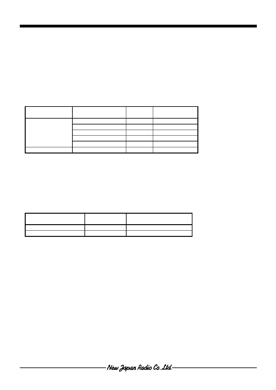
Table 1 Delay Circuits and Extra Features.
Detection Block
Delay Circuit
Extra Feature
Low Voltage Malfunction
Prevention Circuit
Hysteresis
CHG-SW Hysteresis
Battery Connected
Detection
Hysteresis
Temperature Detection
Hysteresis
Full Charge Detection
�
Re-Charge Detection
�
Low Voltage Detection
Hysteresis
Over Voltage Detection
Delay I
Latch
Quick Charge Detection
Delay II
Hysteresis
The delay circuit block receives a signal from the timer circuit to fix a delay time.
For details on the relationship between the delay time and capacitors see "6. Timer Circuit Block".
6. Timer Circuit Block (C1 pin, C2 pin)
OSC1 is used for the timer that is used for pre-charge, 2mA charge and the like. OSC2 is used for the quick charge timer.
You can change the time of the timers with external capacitors. Tables 2, 3 show the relationship between capacitance and
time.
Table 2 C1, C2 Oscillation Cycle t
Capacitance (C1, C2)
Oscillation Cycle
(OSC1, OSC2)
4700pF t
=
4.7ms
0.01
�
F
t = 10ms
0.022
�
F
t = 22ms
0.047
�
F
t = 47ms
Table 3 Timer Time
Use capacitors the have good temperature characteristics in the OSC block.
Capacitor deviation will cause timer errors.
Block Name
Parameter
Calculation
Formula
Examples
2mA Charge Timer
tx2
10
10.2s
Pre-Charge Timer
tx2
17
22min.
LED R Blinking Cycle
tx2
7
1.28s
Delay I
tx2
5
0.32s
Pre-Charge Timer
Delay II
tx2
4
0.16s
C1=0.01
�
F
Quick Charge Timer
Quick Charge Timer
tx2
20
2hours
55
min. C2=0.01
�
F
NJW4120
- 14 -
Ver.2005-03-09
FEATURE DESCRIPTION (CONTINUED)
In each charge mode if time-over occurs charging is prohibited and LED-R blinks. Turning the power off to release UVLO,
battery connection detection, or CHG-SW switching will enable the charge sequence to restart.
NJW4120 incorporates a test mode that shortens the timer block function's test time by 1/150,000.
To operate in test mode set the TH pin voltage to a value no greater than that of the TL pin. In test mode, regardless of the
external timing capacitors C1, C2, the internal timer clock frequency will operate in a range of approximately 200kHz to
300kHz. The following shows calculation values when the oscillating frequency is 250kHz (4
�
s cycle).
Table 4. Timer Times in Test Mode.
When the TDET pin voltage is approximately 1.2V or greater, the pre-charge / quick charge timers operate normally.
If you want to further reduce the test time, setting TDET pin voltage makes it possible to run each of the timer counters
divided in half. When the TDET pin is approximately 0.3V or less, the first half of the counter is bypassed. When the voltage
is approximately greater than 0.4V and less than 1.1V, the second half of the counter is bypassed.
Table 5. Reduced Test Time Mode
Block Name
Parameter
Calculation
Formula
Example
(t = Appx. 4
�
s)
2mA Charge Timer
tx2
10
Appx.
4ms
Pre-Charge Timer
tx2
17
Appx.
0.5s
LED R Blinking Cycle
tx2
7
Appx.
0.5ms
Delay I
tx2
5
Appx.
0.13ms
Pre-Charge Timer
Delay II
tx2
4
Appx. 64
�
s
Quick Charge Timer
Quick Charge Timer
tx2
20
Appx.
4.2s
Parameter
Calculation
Formula
Example (t =Appx. 4
�
s)
Pre-Charge Timer
tx2
8
, tx2
8
Appx.
1ms,
Appx.
1ms
Quick Charge Timer
tx2
9
, tx2
10
Appx.
2ms,
Appx.
4ms

NJW4120
- 15 -
Ver.2005-03-09
FEATURE DESCRIPTION (CONTINUED)
7. Reference Voltage Block (VREF pin)
This block generates 1.24V and 4.2V reference voltages. The VREF pin outputs 1.24V. In addition to the IC internal
reference voltage, this is also used as a reference voltage for charge current setting and temperature detection setting.
8. Power Block,
Under Voltage Lockout
Circuit (UVLO) Block (V
+
pin, GND pin)
An integrated
Under Voltage Lockout
circuit prevents IC malfunction when power is turned on or off. This circuit
incorporates a 200mV hysteresis width to prevent chattering.
As required, insert a bypass capacitor near the IC's V
+
pin when there is power line noise or when wires are long.
9. LED Block (LED-R pin, LED-G pin)
The 2 LEDs can indicate charge status. (Figure 5)
The LED drive circuit is an open collector output configuration.
Therefore, it is easy to set a constant LED drive current with resistance values.
The expression for setting the current that flows through the LEDs is shown below.
I
LED-G
(Vcc - V
F-LED
- V
OL-G
) / R
LED
or
I
LED-R
(Vcc - V
F-LED
- V
OL-R
) / R
LED
Figure 5. LED Drive Circuit
LED-G
LED-R
Input
V
F-LED
I
LED
R
LED
NJW4120
- 16 -
Ver.2005-03-09
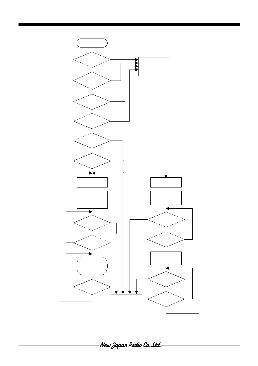
FLOW CHART
Start
Pre-Charge
Timer Start
YES
NO
Check
Adapter Voltage
V
+
>2.4V
Check
Battery Temp.
V
TL
<V
TDET
<V
TH
YES
NO
YES
NO
Check
Battery Voltage
V
BAT
<V
OV
YES
NO
Check
Voltage
V
BAT
>V
Q-CHG
Quick Charge
Timer Start
Quick Charge Start
LED-G: OFF
LED-R: ON
TX-SW:ON
YES
NO
Time Out
YES
NO
Battery
Battery Voltage
V
BAT
>V
Q-CHG
Time Out
NO
Check
Full Charge
I
BAT
<I
F-CHG
YES
Charge Complete
LED-G: ON
LED-R: OFF
TX-SW:OFF
Check
Battery Voltage
V
BAT
<V
R-CHG
YES
NO
NO
YES
Check
Battery Connection
CHG-SW Pin=GND
YES
NO
Abnormal Charging
Prohibited
LED-G: OFF
LED-R: OFF
TX-SW:OFF
LED-G: OFF
LED-R: ON
2mA Charge: ON
Abnormal Charging
Prohibited
LED-G: OFF
LED-R: ON/OFF
TX-SW:OFF
Pre-Charge Start
2mACharge: OFF
TX-SW:ON
YES
NO
Check
Battery Voltage
V
BAT
>V
LV
YES
NO
Time Out
NO
Check
Battery Connection
V
TDET
<1.15V
YES
Adaptor voltage, Battery connection,
Battery Temp. and Battery voltage are
monitored during charging.
When charging is prohibited, one of the
following action resumes the charging;
Unplug and plug power supply
Remove and set batteries
Charge-SW ON/OFF

NJW4120
- 17 -
Ver.2005-03-09
TIMING CHART
0V
CHG-SW
LED-R
LED-G
ON
ON
OFF
ON
ON
OFF
OFF
OFF
0V
TX-SW
ON
OFF ON
ON
OFF
OFF
Battery Voltage
Charge Current
Pre-
Charge
Quick
Charge
Constant
Voltage
Charge
Full
Charge
Re-
Charge
Pre-Charge Current
Full Charge Current
Quick Charge
Detecting Voltage
Quick Charge Current
Charge Control Voltage
Re-Charge Detecting Voltage
Adaptor Voltage
Charge Control Mode
Adaptor Output Mode
The timing chart at the time of protection circuit operation
In addition to a charge timing chart, a protection circuit with a built-in IC operates according to the state and
circumference environment of a battery.
The timing chart when various protection circuits operate is as follows.
Pre-charge
time
out Quick charge time out
Battery Voltage
0V
Charge Current
CHG-SW
LED-R
LED-G
ON
Quick charge detecting voltage
ON
OFF
OFF
Adaptor Voltage
0V
TX-SW
OFF
ON
OFF
Pre-charge
! 22min* "
OFF
ON/OFF 1.28s*
Battery Voltage
0V
Charge Current
CHG-SW
LED-R
LED-G
ON
Charge Voltage
ON
OFF
OFF
Adaptor Voltage
0V
TX-SW
OFF
ON
OFF
Quick charge
! 3h* "
OFF
ON/OFF
Full charge
detection
60mA*
C1=0.01
�
F C2=0.01
�
F

NJW4120
- 18 -
Ver.2005-03-09
The timing chart at the time of protection circuit operation (Continued)
Over voltage battery (Return)
Over voltage battery(Abnormalities)
Battery voltage
0V
Charge Current
CHG-SW
LED-R
LED-G
ON
Low voltage
Detecting voltage
ON
OFF
OFF
Adaptor voltage
0V
TX-SW
OFF
ON
OFF
Pre-charge
2mA
Battery voltage
0V
Charge Current
CHG-SW
LED-R
LED-G
ON
ON
OFF
OFF
Adaptor voltage
0V
TX-SW
OFF
OFF
Charge
STOP
2mA
ON/OFF 1.28s*
Charge voltage
2mAcharge
! 10s* "
C1=0.01
�
F
2mAcharge
! 10s* "
C1=0.01
�
F
Low voltage
Detecting voltage
Over charge battery
Abnormalities in temperature
Battery Voltage
0V
Charge Current
CHG-SW
LED-R
LED-G
ON
OFF
Adaptor Voltage
0V
TX-SW
OFF
OFF
Charge STOP
Battery Voltage
0V
Charge Current
CHG-SW
LED-R
LED-G
ON
OFF
OFF
Adaptor Voltage
0V
TX-SW
OFF
OFF
Charge STOP
Temperature
Detecting
ON
Over charge detecting
OFF
ON/OFF 1.28s*
C1=0.01
�
F

NJW4120
- 19 -
Ver.2005-03-09
OPERATION MATRIX
Parameter
Adaptor
Mode
Quick
Charge
Pre-
Charge
2mA
Charge
Full
Charge
Temperature
Error
Over
Voltage
Error
Time OUT
LED-G OFF OFF OFF OFF ON
OFF OFF OFF
LED-R OFF
ON
ON ON OFF OFF
BLINKING BLINKING
SW-Tr. OFF ON ON OFF OFF OFF OFF OFF
Control Mode
Adaptor
Charge
Adaptor
Adaptor
Adaptor
Adaptor
Adaptor
Adaptor
Charge Current
-
Q-CHG
P-CHG
2mA
-
-
-
-
Return Charge
-
-
-
-
Re-Charge
Auto
Latch
Latch
Timer Stop
Operate
Operate
Operate
Stop Stop Stop -
Temperature
Detecting
Disregard Operate Operate
Operate
Operate
-
Operate Operate
Over Voltage
Detecting
Disregard Operate Operate
Operate
Operate
Operate
-
Operate
CHG-SW Stay
Operate
Operate
Operate
Operate
Re-start
Re-start
Re-start
Battery Setting
Stay
Operate Operate
Operate
Operate
Re-start
Re-start
Re-start
Full Charge
Detecting
Disregard Operate Operate Disregard
-
Disregard Disregard
Disregard
Disregard: Detection function is not reflected in control although it is operating.
LED ON/OFF PATTERN
*Available upon request.
NJW4120
NJW4125*
NJW4126*
NJW4127*
Parameter
LED-R
LED-G
LED-R
LED-G
LED-R
LED-G
LED-R
LED-G
Adaptor Voltage
OFF OFF OFF OFF
ON
OFF
ON
OFF
Charging
ON
OFF
ON
OFF
ON
BLINKING
ON
BLINKING
Full Charging
OFF
ON
OFF
ON
ON
ON
ON
ON
Temperature Error
OFF OFF
BLINKING
OFF OFF OFF
BLINKING
OFF
Over Voltage Detecting
BLINKING
OFF
BLINKING
OFF
BLINKING
OFF
BLINKING
OFF
Time Out
BLINKING
OFF
BLINKING
OFF
BLINKING
OFF
BLINKING
OFF

NJW4120
- 20 -
Ver.2005-03-09
MEMO
[CAUTION]
The specifications on this databook are only
given for information , without any guarantee
as regards either mistakes or omissions. The
application circuits in this databook are
described only to show representative usages
of the product and not intended for the
guarantee or permission of any right including
the industrial rights.