NT7603
Single-Chip 16C X 2L Dot-Matrix LCD Controller / Driver
1
V2.2
Features
!
Internal LCD drivers
16 common signal drivers
80 segment signal drivers
!
Maximum display dimensions
16 characters X 2 lines or
32 characters X 1 line
!
Interfaces with 4-bit or 8-bit MPU
!
Versatile display functions provided on chip:
Display Clear, Cursor Home, Display ON/OFF,
Cursor ON/OFF, Character Blinking, Cursor
Shift, and Display Shift
!
Three duty factors, selected by PROGRAM:
1/8, 1/11, and 1/16
!
Displays Data RAM (DD RAM): 80 X 8 bits
(Displays up to 80 characters)
!
Character Generator RAM (CG RAM):
64 X 8 bits for general data,
8
5 X 8 programmable dot patterns, or
4
5 X 10 programmable dot patterns
!
Low voltage reset
!
ITO option for A-type and B-type LCD waveform
!
Character Generator ROM (CG ROM):
2 kinds of CG ROM sizes:
192
characters:
160
5 X 8 dot patterns
32
5 X 10 dot patterns
240
characters:
192
5 X 8 dot patterns
48
5 X 10 dot patterns
Custom CG ROM is also available
!
Built-in power-on reset function
!
Logic power supply: 2.8V ~ 5.5V
!
LCD driver power supply: V1 ~ V5
(V
DD
+ 0.3 - V
DD
- 7.0), divided by Built-in LCD power
division resister.
!
Two oscillator operations
(Freq. = 500KHz - 540KHz):
� Built-in RC oscillation
� External clock
!
CMOS Process
!
Available in COG FORM
General Description
The NT7603 is a dot matrix LCD controller and driver LSI that
can operate with either a 4-bit or an 8-bit microprocessor
(MPU). The NT7603 receives control character codes from
the MPU, stores them in an internal RAM (up to 80
characters) before transforming each character code into a 5
X 7, 5 X 8, or 5 X 10 dot matrix character pattern and then
displaying the codes on the LCD panel. The built-in
Character Generator ROM consists of 256 different
character patterns.
The NT7603 also contains Character Generator RAM where
the user can store 8 different character patterns at run time.
These memory features make the character display flexible.
NT7603 also provides many display instructions to achieve
versatile LCD display functions. The NT7603 is fabricated on
a single LSI chip using the CMOS process, resulting in very
low power requirements.
NT7603
4
V2.2
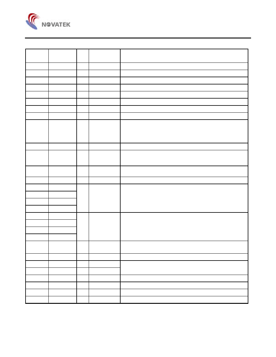
Pad Description (Total 166 pads for COG type)
Pad No.
Designation
I/O
External
Connection
Description
1 - 15
GND
P Power
supply
GND: 0V
16
OSC1
I
For external clock operation, clock inputs to OSC1
17 OSC2
O Clock
output
18 V1
P
Power supply
Power supply for LCD driver. V
DD
V1 V2 V3 V4 V5 GND
19 V2
P
Power supply
Power supply for LCD driver
20 V3
P
Power supply
Power supply for LCD driver
21 V4
P
Power supply
Power supply for LCD driver
22 - 25
V5
P
Power supply
Power supply for LCD driver
26, 28
OPT_R0,
OPT_R1
I ITO
Option
The built-in bias resister select:
OPT_R1, OPT_R0: No ITO = 1. ITO on = 0
1, 1: 2.2K; 1, 0: 4K;
0, 1: 6.8K; 0, 0:No built-in bias resistor
29 - 43
V
DD
P Power
supply
V
DD
: +5V
44, 45
RS
I
MPU
Register select signal
0: Instruction register (write), Busy flag, address counter (read)
1: Data register (write, read)
46, 47
R/W
I
MPU
Read/Write control signal
0: Write 1: Read
48, 49
E
I
MPU
Read/Write start signal
50, 51
DB0
52, 53
DB1
54, 55
DB2
56, 57
DB3
I/O MPU
Lower 4 tri-state bi-directional data bus for transmitting data
between MPU and NT7603. Not used during 4-bit operation.
58, 59
DB4
60, 61
DB5
62, 63
DB6
64, 65
DB7
I/O MPU
Higher 4 tri-state bi-directional data bus for transmitting data
between MPU and NT7603. DB7 is also used as a busy flag.
66 OPT_LCD I ITO
Option
No ITO. (Option = 1): B-Type waveform
ITO On. (Option = 0): A-Type waveform
68
TESTD
O
Test output
Test data output. (No connect for user)
164 - 157 COM1 - 8
O
LCD panel
69 - 76,
COM9 - 16
O
LCD panel
Common signal output pins, for place on the upper glass
(IC face up)
156 - 77
SEG1 - 80
O
LCD panel
Segment signal output pins
165
TEST
I
Test pin
Test pin (internal pull down) (No connection for user)
166 TESTM O
Test
output
LCD driver clock output. (No connection for user)
67, 27
GND_OUT
P
GND output pin, used for pull-down ITO option

NT7603
5
V2.2
Functional Description
The NT7603 is a dot-matrix LCD controller and driver LSI. It
operates with either a 4-bit or an 8-bit microprocessor (MPU).
The NT7603 receives both instructions and data from the
MPU. Some instructions set operation modes, such as the
function mode, data entry mode, and display mode; as well
as some control LCD display functions, such as clear display,
restore display, shift display, and cursor. Other instructions
include reading and writing both data and addresses. All
instructions allow users convenient and powerful functions to
control the LCD dot-matrix displays.
Data is written into, and read from the Data Display RAM (DD
RAM) or the Character Generator RAM (CG RAM). As
display character codes, the data stored in the DD RAM
decodes a set of dot-matrix character patterns that are built
into the Character Generator ROM (CG ROM). The CG
ROM, with many character patterns (up to 256 patterns),
defines the character pattern fonts. The NT7603 regularly
scans the character patterns through the segment drivers.
The CG RAM stores character pattern fonts at run time if
users intend to show character patterns that are not defined
in the CG ROM. This feature makes character display
flexible. Other unused bytes can be used as general-purpose
data storage.
The LCD driver circuit consists of 16 common signal drivers
and 80 segment signal drivers allowing a variety of
application configurations to be implemented.
Character Generator ROM (CG ROM)
The character generator ROM generates LCD dot character
patterns from the 8-bit character pattern codes. The NT7603
provides 2 CG ROM configurations:
1. 192 Characters:
The CG ROM contains 160 5 X 8 dot character patterns and
32 5 X 10 dot character patterns. The relation between the
character codes and character patterns is shown in Table 1.
The character codes from 00H to 0FH are used to get
character patterns from the CG RAM. Character codes from
10H to 1FH, from 80H to 9FH and 20H map to null character
patterns. Character codes from E0H to FFH are assigned to
generate 5 X 10 dot character patterns, and other codes are
used to generate 5x8 dot character patterns.
2. 240 Characters:
The CG ROM contains 192 5 X 8 dot character patterns and
48 5 X 10 dot character patterns. The relation between the
character codes and character patterns is shown in Table 2.
The character codes from 00H to 0FH are used to get
character patterns from the CG RAM. Character codes from
10H to 1FH and from E0H to FFH are assigned to generate 5
X 10 dot character patterns, and other codes to generate 5 X
8 dot character patterns. Only one null character pattern
exists in this type. Note that the underlined cursor, displayed
on the 8th duty may be obscure if the 8th row of a dot
character pattern is coded. We recommend that users
display the cursor in the blinking mode if they code 5x8 dot
character patterns as their custom CG ROM.
Custom character patterns are available by
mask-programming ROM. For convenience of character
pattern development, NOVATEK has developed a
user-friendly editor program for the NT7603 to help
determine the character patterns users prefer. By executing
the program on the computer, users can easily create and
modify their character patterns. By transferring the resulting
files generated by the program through a modem or some
other communication method, the user and NOVATEK will
have established a reliable, fast link for programming the CG
ROM.