LM185-1.2/LM285-1.2/LM385-1.2
Micropower Voltage Reference Diode
General Description
The
LM185-1.2/LM285-1.2/LM385-1.2
are
micropower
2-terminal band-gap voltage regulator diodes. Operating
over a 10 ĶA to 20 mA current range, they feature exception-
ally low dynamic impedance and good temperature stability.
On-chip trimming is used to provide tight voltage tolerance.
Since the LM185-1.2 band-gap reference uses only transis-
tors and resistors, low noise and good long term stability re-
sult.
Careful design of the LM185-1.2 has made the device ex-
ceptionally tolerant of capacitive loading, making it easy to
use in almost any reference application. The wide dynamic
operating range allows its use with widely varying supplies
with excellent regulation.
The extremely low power drain of the LM185-1.2 makes it
useful for micropower circuitry. This voltage reference can be
used to make portable meters, regulators or general purpose
analog circuitry with battery life approaching shelf life.
Further, the wide operating current allows it to replace older
references with a tighter tolerance part.
The LM185-1.2 is rated for operation over a -55įC to 125įC
temperature range while the LM285-1.2 is rated -40įC to
85įC and the LM385-1.2 0įC to 70įC. The LM185-1.2/
LM285-1.2 are available in a hermetic TO-46 package and
the LM285-1.2/LM385-1.2 are also available in a low-cost
TO-92 molded package, as well as SO and SOT-23. The
LM185-1.2 is also available in a hermetic leadless chip car-
rier package.
Features
n
Ī
4 mV (
Ī
0.3%) max. initial tolerance (A grade)
n
Operating current of 10 ĶA to 20 mA
n
0.6
max dynamic impedance (A grade)
n
Low temperature coefficient
n
Low voltage reference -- 1.235V
n
2.5V device and adjustable device also available
n
LM185-2.5 series and LM185 series, respectively
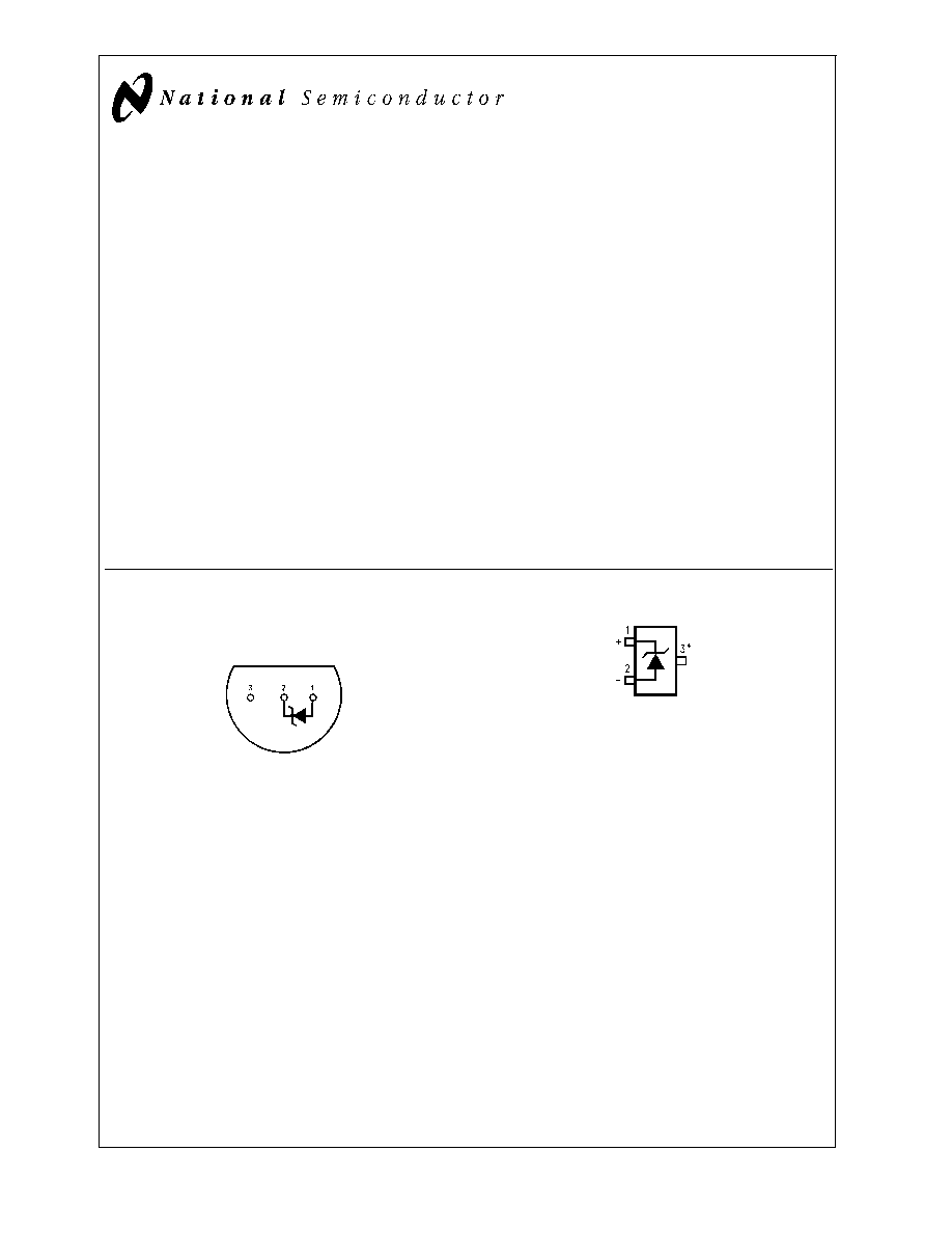
Connection Diagrams
T0-92
Plastic Package (Z)
DS005518-10
Bottom View
Order Number LM285Z-1.2,
LM285BXZ-1.2, LM285BYZ-1.2
LM385Z-1.2, LM385BZ-1.2
LM385BXZ-1.2 or LM385BYZ-1.2
See NS Package Number Z03A
SOT23
DS005518-33
*
Pin 3 is attached to the Die Attach Pad (DAP) and should be connected
to Pin 2 or left floating.
Order Number LM385M3-1.2
See NS Package Number MA03B
January 2000
LM185-1.2/LM285-1.2/LM385-1.2
Micropower
V
oltage
Reference
Diode
© 2000 National Semiconductor Corporation
DS005518
www.national.com
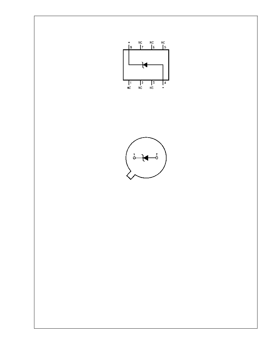
Connection Diagrams
(Continued)
SO Package
DS005518-9
Order Number LM285M-1.2,
LM285BXM-1.2, LM285BYM-1.2
LM385M-1.2, LM385BM-1.2
LM385BXM-1.2 or LM385BYM-1.2
See NS Package Number M08A
TO-46
Metal Can Package (H)
DS005518-6
Bottom View
Order Number LM185H-1.2, LM185H-1.2/883,
LM185BXH-1.2, LM185BYH-1.2
LM285H-1.2 or LM285BXH-1.2
See NS Package Number H02A
LM185-1.2/LM285-1.2/LM385-1.2
www.national.com
2
Absolute Maximum Ratings
(Note 1)
If Military/Aerospace specified devices are required,
please contact the National Semiconductor Sales Office/
Distributors for availability and specifications.
(Note 2)
Reverse Current
30 mA
Forward Current
10 mA
Operating Temperature Range (Note 3)
LM185-1.2
-55įC to +125įC
LM285-1.2
-40įC to +85įC
LM385-1.2
0įC to 70įC
Storage Temperature
-55įC to +150įC
Soldering Information
TO-92 package: 10 sec.
260įC
TO-46 package:10 sec.
300įC
SO and SOT Pkg.
Vapor phase (60 sec.)
215įC
Infrared (15 sec.)
220įC
See AN-450 "Surface Mounting Methods and Their Effect
on Product Reliability" for other methods of soldering
surface mount devices.
Electrical Characteristics
(Note 4)
LM185-1.2
LM185BX-1.2
LM385B-1.2
LM185BY-1.2
LM385BX-1.2
LM385-1.2
LM285-1.2
LM385BY-1.2
Units
Parameter
Conditions
Typ
LM285BX-1.2
(Limit)
LM285BY-1.2
Tested
Design
Tested
Design
Tested
Design
Limit
Limit
Limit
Limit
Limit
Limit
(Notes
5, 8)
(Note 6)
(Note 5)
(Note 6)
(Note 5)
(Note 6)
Reverse Breakdown
T
A
= 25įC,
1.235
1.223
1.223
1.205
V(Min)
Voltage
10 ĶA
I
R
20 mA
1.247
1.247
1.260
V(Max)
Minimum Operating
8
10
20
15
20
15
20
ĶA
Current
LM385M3-1.2
10
15
(Max)
Reverse Breakdown
10 ĶA
I
R
1 mA
1
1.5
1
1.5
1
1.5
mV
Voltage Change
(Max)
with Current
1 mA
I
R
20 mA
10
20
20
25
20
25
mV
(Max)
Reverse Dynamic
I
R
= 100 ĶA, f = 20 Hz
1
Impedance
Wideband Noise
I
R
= 100 ĶA,
60
ĶV
(rms)
10 Hz
f
10 kHz
Long Term Stability
I
R
= 100 ĶA, T = 1000 Hr,
20
ppm
T
A
= 25įC
Ī
0.1įC
Average Temperature
I
R
= 100 ĶA
Coefficient (Note 7)
X Suffix
30
30
ppm/įC
Y Suffix
50
50
ppm/įC
All Others
150
150
150
ppm/įC
(Max)
Note 1: Absolute Maximum Ratings indicate limits beyond which damage to the device may occur. Operating Ratings indicate conditions for which the device is in-
tended to be functional, but do not guarantee specific performance limits. For guaranteed specifications and test conditions, see the Electrical Characteristics. The
guaranteed specifications apply only for the test conditions listed.
Note 2: Refer to RETS185H-1.2 for military specifications.
Note 3: For elevated temperature operation, T
j
max is:
LM185
150įC
LM285
125įC
LM385
100įC
Thermal Resistance
TO-92
TO-46
SO-8
SOT23
JA
(junction to ambient)
180įC/W (0.4" leads)
440įC/W
165įC/W
283įC/W
170įC/W (0.125" leads)
JC
(junction to case)
N/A
80įC/W
N/A
N/A
Note 4: Parameters identified with boldface type apply at temperature extremes. All other numbers apply at T
A
= T
J
= 25įC.
LM185-1.2/LM285-1.2/LM385-1.2
www.national.com
3
Electrical Characteristics
(Note 4) (Continued)
Note 5: Guaranteed and 100% production tested.
Note 6: Guaranteed, but not 100% production tested. These limits are not used to calculate average outgoing quality levels.
Note 7: The average temperature coefficient is defined as the maximum deviation of reference voltage at all measured temperatures between the operating T
MAX
and T
MIN
, divided by T
MAX
- T
MIN
. The measured temperatures are -55įC, -40įC, 0įC, 25įC, 70įC, 85įC, 125įC.
Note 8: A military RETS electrical specification is available on request.
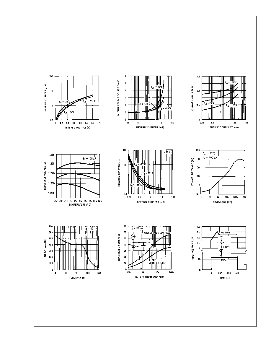
Typical Performance Characteristics
Reverse Characteristics
DS005518-13
Reverse Characteristics
DS005518-14
Forward Characteristics
DS005518-15
Temperature Drift of 3
Representative Units
DS005518-16
Reverse Dynamic Impedance
DS005518-17
Reverse Dynamic Impedance
DS005518-18
Noise Voltage
DS005518-19
Filtered Output Noise
DS005518-20
Response Time
DS005518-21
LM185-1.2/LM285-1.2/LM385-1.2
www.national.com
4
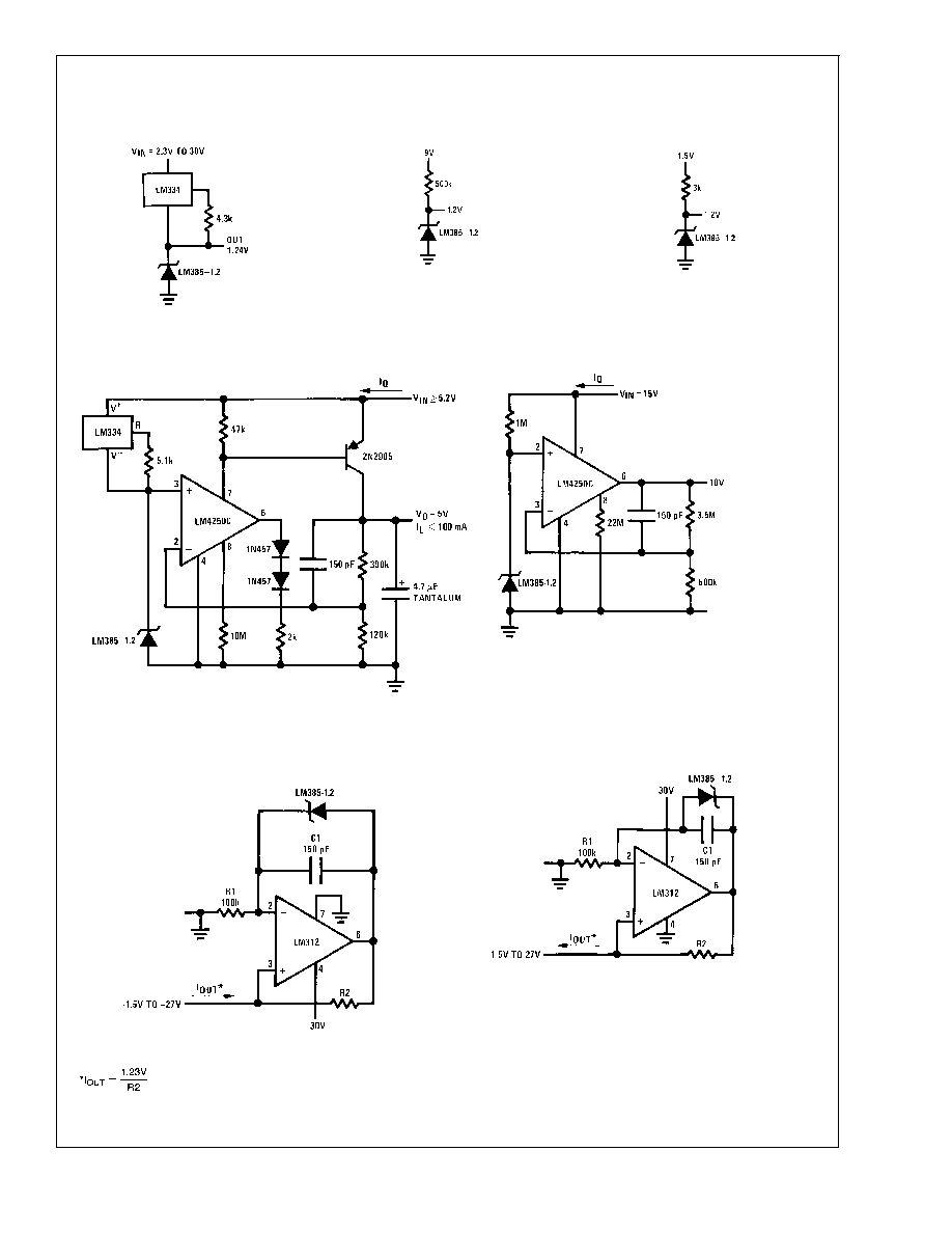
Typical Applications
Wide Input
Range Reference
DS005518-8
Micropower Reference
from 9V Battery
DS005518-22
Reference from
1.5V Battery
DS005518-23
Micropower
*
5V Regulator
DS005518-24
*I
Q
30 ĶA
Micropower
*
10V Reference
DS005518-25
*I
Q
20 ĶA standby current
Precision 1 ĶA to 1 mA Current Sources
DS005518-26
DS005518-27
LM185-1.2/LM285-1.2/LM385-1.2
www.national.com
5