Original Creation Date: 07/31/98
Last Update Date: 07/19/99
Last Major Revision Date: 05/05/99
MNDS26LV31-X REV 1A0
MICROCIRCUIT DATA SHEET
3V ENHANCED CMOS QUAD DIFFERENTIAL LINE DRIVER
General Description
The DS26lV31 is a high-speed quad differential CMOS driver that is comparable to the
TIA/EIA-422-B and ITU-T V.11 standards. The CMOS DS26LV31 features low static ICC of 125
uA Max which makes it ideal for battery powered and power conscious applications.
Differential outputs have the same VOD guarantee (>2V) as the 5V version.
The EN and EN inputs allow active Low or active High control of the TRI-STATE outputs.
The enables are common to all four drivers. Protection diodes protect all the driver
inputs against electrostatic discharge. The driver and enable inputs (DI, EN, EN) are
compatible with low voltage LVTTL and LVCMOS devices.
NS Part Numbers
DS26LV31W-QML
Industry Part Number
DS26LV31
Prime Die
DS26LV31
Controlling Document
9858401QFA
Processing
MIL-STD-883, Method 5004
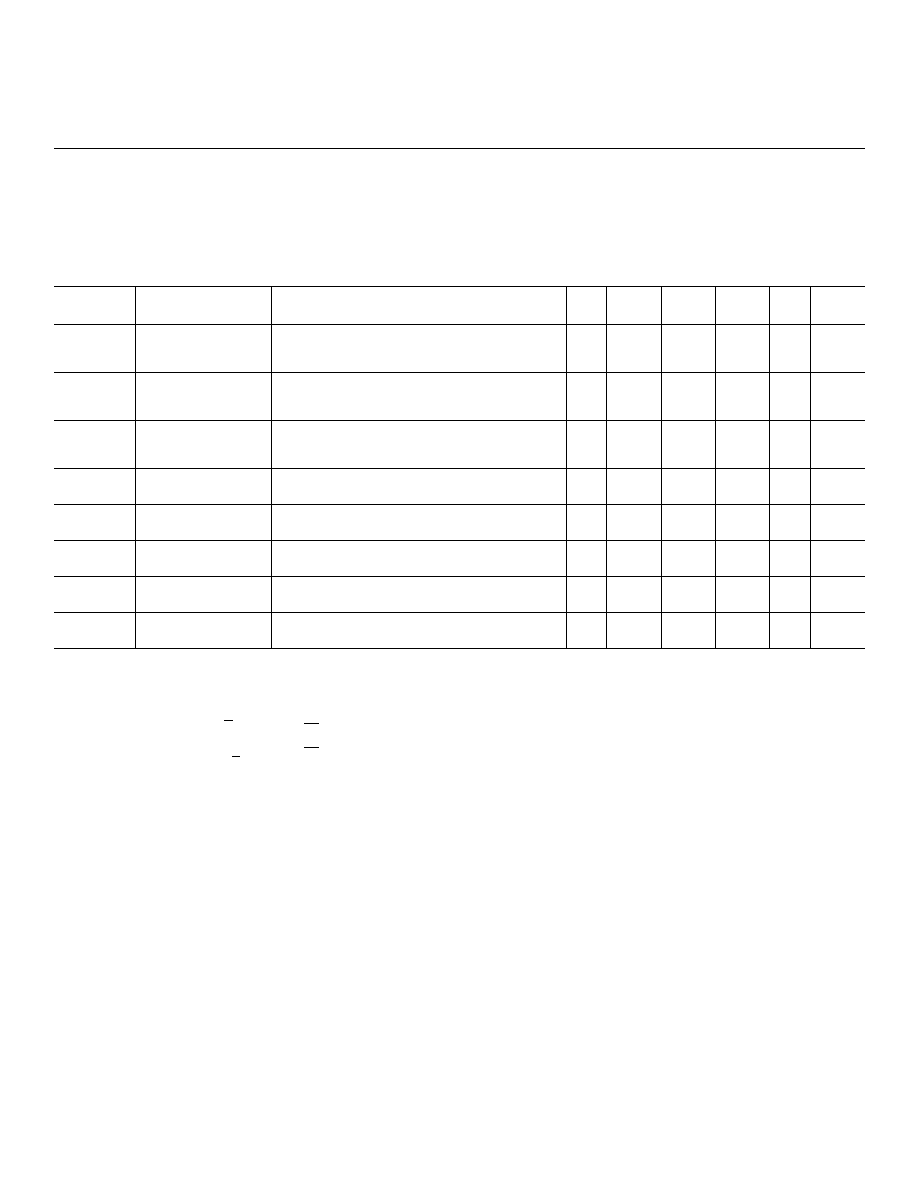
Quality Conformance Inspection
MIL-STD-883, Method 5005
Subgrp Description Temp ( C)
o
1
Static tests at
+25
2
Static tests at
+125
3
Static tests at
-55
4
Dynamic tests at
+25
5
Dynamic tests at
+125
6
Dynamic tests at
-55
7
Functional tests at
+25
8A
Functional tests at
+125
8B
Functional tests at
-55
9
Switching tests at
+25
10
Switching tests at
+125
11
Switching tests at
-55
1

MICROCIRCUIT DATA SHEET
MNDS26LV31-X REV 1A0
Features
- Outputs won't load line when Vcc = 0V
- Comparable to both EIA RS-422 and ITU-T V.11 standards.
- TRI-STATE outputs for connection to system buses
- Low quiescent current
- ESD Rating (HBM, 1.5K ohm, 100pF) >2500V
- Typical Part to Part Skew < TBD
2

MICROCIRCUIT DATA SHEET
MNDS26LV31-X REV 1A0
(Absolute Maximum Ratings)
(Note 1, 2)
Supply Voltage (Vcc)
-0.5V to 7.0V
DC Input Voltage (Vin)
-0.5V to Vcc +0.5V
DC Output Voltage (Vout) Power off
-0.5V to 7V
Clamp Diode Current (Iik, Iok)
+ 20mA
DC Output Current, per Pin (Iout)
+ 150mA
Storage Temperature Range (Tstg)
-65 C to +150 C
Lead Temperature (Tl)
260 C
(Soldering, 4 seconds)
Maximum Power Dissipation +25C
(Note 3)
1119mW
Thermal Resistance. (Theta JA)
134 C/Watt
Thermal Resistance. (Theta JC)
12.5 C/Watt
Note 1:
Absolute Maximum Ratings are those values beyond which the safety of the device
cannot be guaranteed. They are not meant to imply that the device should be operated
at these limits. The table of "Electrical Characteristics" provide conditions for
actual device operation.
Note 2:
Unless otherwise specified, all voltages are referenced to ground. All currents into
device pins are positive, all currents out of device pins are negative.
Note 3:
Derate W package 7.5mW/C above +25C.
Recommended Operating Conditions
Supply Voltage (Vcc)
3.0V to 3.6V
DC Input or Output Voltage (Vin, Vout)
0V to Vcc
Operating Temperature Range (TA)
-55 C to +125 C
3

MNDS26LV31-X REV 1A0
MICROCIRCUIT DATA SHEET
Electrical Characteristics
SYMBOL
PARAMETER
CONDITIONS
NOTES
PIN-
NAME
MIN
MAX
UNIT
SUB-
GROUPS
Vih
Logical "1" Input
Voltage
3
2.0
V
1, 2,
3
Vil
Logical "0" Input
Voltage
3
0.8
V
1, 2,
3
Vod1
Differential
Output Voltage
Rl= (No Load), Vcc=3.0/3.6V
1
4.0
V
1, 2,
3
Vod2
Differential
Output Voltage
Rl= 100 Ohms, Vcc=3.0/3.6V
1
2.0
3.2
V
1, 2,
3
Vod2-Vod2
Difference in
Differential
Output
Rl=100 Ohms, Vcc=3.0/3.6V
1
-0.4
0.4
V
1, 2,
3
Vod3
Differential
Output Voltage
Rl=3900 Ohms, Vcc=3.0/3.6V
1
3.6
V
1, 2,
3
Voc
Common Mode
Output Voltage
Rl=100 Ohms, Vcc=3.0/3.6V
1
2.0
V
1, 2,
3
Voc-Voc
Difference in
Common Mode
Output
Rl=100 Ohms, Vcc=3.0/3.6V
1
-0.4
0.4
V
1, 2,
3
Iil
Low Level Input
Current
Vin=Gnd, Vcc=3.6V
-10
uA
1, 2,
3
Iih
High Level Input
Current
Vin=Vcc, Vcc=3.6V
10
uA
1, 2,
3
Vcl
Input Clamp
Voltage
Iin=-18mA, Vcc=3.0V
-1.5
V
1, 2,
3
Icc
Quiescent Power
Supply Current
Iout=0uA, Vin=Vcc or Gnd, Vcc=3.6V
125
uA
1, 2,
3
Ioz
TRI-STATE Output
Leakage Current
Vout=Vcc or Gnd, Enable=Vil, Vcc=3.6V,
Enable = Vih
+ 20
uA
1, 2,
3
Isc
Output Short
Circuit Current
Vin=Vcc or Gnd, Vcc=3.0/3.6V
Vout=0.0V
1, 2
-30
-160
mA
1, 2,
3
Ioff
Output Leakage
Current "Power
Off"
Vcc=0V, Vout=6.0V or 3.0V
100
uA
1, 2,
3
Vcc=0V, Vout= -0.25V
-200
uA
1, 2,
3
4
MNDS26LV31-X REV 1A0
MICROCIRCUIT DATA SHEET
Electrical Characteristics
AC PARAMETERS: PROPAGATION DELAY TIME:
(The following conditions apply to all the following parameters, unless otherwise specified.)
AC:
Vcc=3.0/3.6V
SYMBOL
PARAMETER
CONDITIONS
NOTES
PIN-
NAME
MIN
MAX
UNIT
SUB-
GROUPS
tPLHD
Differential
Propagation Delay
(Low to High)
Rl=100 Ohms, Cl=50pF
4
5
25
nS
9, 10,
11
tPHLD
Differential
Propagation Delay
(High to Low)
Rl=100 Ohms, Cl=50pF
4
5
25
nS
9, 10,
11
tSKD
Differential Skew
tpHLD-tpLHD
(same channel)
Rl=100 Ohms, Cl=50pF
4
5
nS
9, 10,
11
tSK1
Pin to Pin Skew
(same device)
Rl=100 Ohms, Cl=50pF
4
5
nS
9, 10,
11
tPZH
Output Enable
Time
Rl=110 Ohms to Gnd, Cl=50pF
5
40
nS
9, 10,
11
tPZL
Output Enable
Time
Rl=110 Ohms to Vcc, Cl=50pF
5
40
nS
9, 10,
11
tPHZ
Output Disable
Time
Rl=110 Ohms to Gnd, Cl=50pF
5
35
nS
9, 10,
11
tPLZ
Output Disable
Time
Rl=110 Ohms to Vcc, Cl=50pF
5
35
nS
9, 10,
11
Note 1:
See EIA specification RS-422 for exact test condition.
Note 2:
This is a current sourced when a high output is shorted to Gnd. Only one output at a
time should be shorted.
Note 3:
Parameter tested Go-no-Go only.
Note 4:
Generator waveform is specified as follows: f=1MHZ, duty cycle=50%, Zo=50 Ohms,
tr=tf<6nS. Driver input=0V to 3V with measure points equal to 1.5V. Differential
output Vdiff=Do-Do with measure point equal to 0V.
Note 5:
Generator waveform is specified as follows: f=1MHZ, duty cycle=50%, Zo=50 Ohms,
tr=tf=<6ns. EN/EN inputs = 0V to 3V with measure points equal to 1.5V on the inputs,
to 1.3V on the outputs for ZL and ZH, and (Vol+0.3V) for LZ, and (Voh-0.3V) for HZ.
5