To aid in the evaluation of the CLC440, CLC446, and
CLC449 series of wide bandwidth parts, National
Semiconductor has created the evaluation boards for the
8-pin DIP, SOIC, and MSOP respectively. All evaluation
boards are optimized for use with high quality surface-
mount resistors and capacitors for obtaining the best high
frequency response.
I. Basic Component Selection
The evaluation boards are laid out for a non-inverting
gain of 2V/V using low-parasitic surface-mount resistors
and capacitors. The CLC44X very high frequency
amplifiers can be sensitive to component parasitics
that may alter AC performance especially in the high
frequency domain. Small adjustments in R
f
and/or R. are
recommended to shape the final desired frequency
response.
For CFB (the CLC446, and CLC449), increasing R
f
from
its recommended value will band limit the device's
frequency response, while decreasing Rf from its
recommended value will peak frequency response.
However, substantially decreasing the feedback resistor
of a current-feedback amp from its recommended value
may cause a part to oscillate. Application note OA-13
"Current-Feedback Amplifier Loop-Gain Analysis and
Performance Enhancements" of the data book elaborates
on the selection of feedback resistors and their influence
on AC performance.
For VFB (the CLC440), increasing both/either R
f
and R
g
from recommended values may cause high frequency
peaking. Decreasing both/either R
f
and R
g
may help
decrease high frequency peaking (without causing
oscillations).
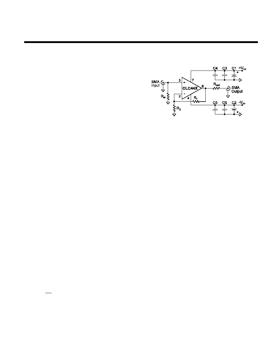
II. Basic Connections & Operation
Both the DIP and SOIC evaluation boards provide for
input and output signal connections through SMA
connectors. These SMAs are connected to the non-
inverting input pin (pin 3) and the R
out
resistor as shown
in Figure 1. The recommended feedback resistor value
for the CLC44X series is 250
. The appropriate gain
setting resistor (R
g
) is calculated with Eq. 1.
The R
out
resistor, of Figure 1, should always be inserted
between pin 6 and the output SMA when driving coaxial
cable or capacitive loads. The plot in the typical
performance section labeled "Settling Time vs. Capacitive
Load" of the data sheets should be used to determine the
optimum resistor value for R
out
when driving coax or
capacitive loads. This optimal resistance improves settling
time for pulse-type applications and increases stability.
Figure 1: Schematic for 73055/60/76 Eval. Boards
Although no DC trim network was included on the evaluation
board, OA-07 has specific circuits to correct DC offsets.
Power-supply bypassing capacitors perform a very
important function for the CLC44X series and should not
be omitted when evaluating these amplifiers. The bypass
capacitors not only provide a low impedance current path
at the supply pin, but also provide high frequency filtering
on the power supply traces. C1 and C2 of Figure 1
should be quality 6.8
�
F tantalum capacitors. C3 and C4
should be quality 0.01
�
F ceramic capacitors. C4 and CS
should be quality 500pF ceramic capacitors.
The use of standard dip sockets is not recommended for
the CLC44X series DIP amplifiers. These sockets may
severely degrade AC performance and may cause oscil-
lations. The 730055 PDIP evaluation board will easily
accommodate flush-mount socket pins when socketing is
necessary. The printed circuit board device holes are sized
for Cambion P/N 450-2598 socket pins or their equivalent.
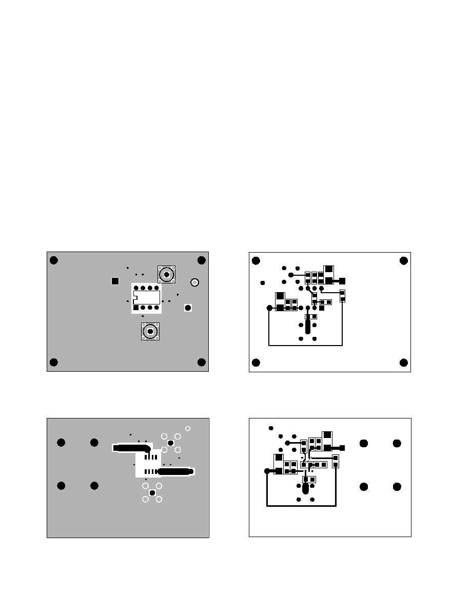
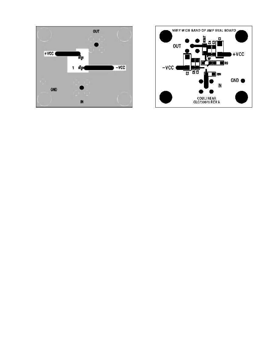
III. Printed Circuit Board Layout Considerations
The evaluation boards have been carefully laid out to
optimize the performance of the CLC44X series. The
ground plane on the evaluation boards was removed
near the sensitive nodes (pins 2, 3, 6) to reduce parasitic
capacitances between these nodes and the ground
plane. Trace lengths were also minimized to reduce
series inductances associated with all components and
all nodes.
The CLC44X series is sensitive to the parasitics on
traces. This sensitivity includes capacitive coupling
from trace to power and trace to ground planes. If
leaded components are used, then a low inductive
resistor supplied by Precision Resistor Products or its
equivalent is highly recommended. In all instances
surface-mount components are recommended over
leaded components.
CLC44X Evaluation Boards
Part Number CLC730055, CLC730060, CLC730076
August 1997
� 1997 National Semiconductor Corporation
http://www.national.com
Printed in the U.S.A.
N
A
1
R
R
Eq. 1
( for A
2 R
R
250 )
v
f
g
v
f
g
= +
= +
=
=
IV. Measurement Hints
If 50
coax and 50
R
in
/R
out
resistors are used, many of
the typical performance plots found in the data sheets for
the CLC44X's are reproducible.
When SMA connectors and cables are not available to
evaluate the CLC44X series, normal oscilloscope probes
should not be used. Alternatively low impedance probes,
of 100 to 500
, should be used. If a low impedance
probe is not available, then a section of 50
coaxial
cable and a low impedance resistor may be used.
Connect one end of coax's center to a test measurement
box terminated in 50
and the other end of the cable's
center conductor to the low impedance resistor. The
open side of the low impedance resistor is now a probe.
The ground shield of the cable should be connected to
evaluation board ground and test box ground. This
cable/resistor probe forms a voltage attenuator between
the resistor and the 50
termination resistance of the test
box. This method allows measurements to be performed
directly on the output pin of the amplifier (pin 6). Since
the CLC44X series has large bandwidths, measurement
equipment should have sufficient bandwidth to accurate-
ly measure pulse and frequency responses of the
CLC44X series.
V. Parts List for Evaluation Boards
Evaluation Board Parts List - Use the device data sheets
with the discussion and examples shown here to select
component values.
I/O connectors (both board styles):
-SMA (straight) Amphenol 901 -144
-SMA (right-angled) Amphenol 901-143
Resistors - 1206 surface-mount type.
Capacitors - Bypassing - 1206 surface-mount type.
Tantalum - TE - Series from Panasonic.
Precision Resistive Products, Inc., Highway 61 South,
Mediapolis, Iowa (319) 394-9131.
http://www.national.com
2
+Vcc
OUT
C1
C4C3
C6C5
C2
IN
Rf
Rin
Rg
Rp
Rout
-Vcc
730055 REV A
VERY WIDEBAND OP AMP EVAL BOARD
+
+
+Vcc
OUT
C1
C4C3
C6C5
C2
IN
Rf
Rin
Rp
Rout
-Vcc
C o m l i n e a r
WIDE BAND OP AMP R&D TEST BOARD
+
+
Rg
-Vcc
GND
OUT
U1
1
+Vcc
IN
COMLINEAR
FORT COLLINS, CO USA
( 970 ) 226 - 0500
-Vcc
OUT
+Vcc
IN
1
PDIP - Top Side
PDIP - Bottom Side
SOIC - Top Side
SOIC - Bottom Side
3
http://www.national.com
MSOP - Top Side
MSOP - Bottom Side

http://www.national.com
4
Lit #660440-002
Customer Design Applications Support
National Semiconductor is committed to design excellence. For sales, literature and technical support, call the National
Semiconductor Customer Response Group at 1-800-272-9959 or fax 1-800-737-7018.
Life Support Policy
National's products are not authorized for use as critical components in life support devices or systems without the express written approval of the
president of National Semiconductor Corporation. As used herein:
1. Life support devices or systems are devices or systems which, a) are intended for surgical implant into the body, or b) support or
sustain life, and whose failure to perform, when properly used in accordance with instructions for use provided in the labeling, can
be reasonably expected to result in a significant injury to the user.
2. A critical component is any component of a life support device or system whose failure to perform can be reasonably expected to
cause the failure of the life support device or system, or to affect its safety or effectiveness.
National Semiconductor
National Semiconductor
National Semiconductor
National Semiconductor
Corporation
Europe
Hong Kong Ltd.
Japan Ltd.
1111 West Bardin Road
Fax: (+49) 0-180-530 85 86
13th Floor, Straight Block
Tel: 81-043-299-2309
Arlington, TX 76017
E-mail: europe.support.nsc.com
Ocean Centre, 5 Canton Road
Fax: 81-043-299-2408
Tel: 1(800) 272-9959
Deutsch Tel: (+49) 0-180-530 85 85
Tsimshatsui, Kowloon
Fax: 1(800) 737-7018
English Tel: (+49) 0-180-532 78 32
Hong Kong
Francais Tel: (+49) 0-180-532 93 58
Tel: (852) 2737-1600
Italiano Tel: (+49) 0-180-534 16 80
Fax: (852) 2736-9960
National does not assume any responsibility for use of any circuitry described, no circuit patent licenses are implied and National reserves the right at any time without notice to change said
circuitry and specifications.
N