
TL F 6395
54LS155DM54LS155DM74LS155
54LS156DM54LS156DM74LS156
Dual
2-Line
to
4-Line
DecodersDemultiplexers
June 1989
54LS155 DM54LS155 DM74LS155
54LS156 DM54LS156 DM74LS156
Dual 2-Line to 4-Line Decoders Demultiplexers
General Description
These TTL circuits feature dual 1-line-to-4-line demultiplex-
ers with individual strobes and common binary-address in-
puts in a single 16-pin package When both sections are
enabled by the strobes the common address inputs se-
quentially select and route associated input data to the ap-
propriate output of each section The individual strobes per-
mit activating or inhibiting each of the 4-bit sections as de-
sired Data applied to input C1 is inverted at its outputs and
data applied at C2 is true through its outputs The inverter
following the C1 data input permits use as a 3-to-8-line de-
coder or 1-to-8-line demultiplexer without external gating
Input clamping diodes are provided on these circuits to mini-
mize transmission-line effects and simplify system design
Features
Y
Applications
Dual 2-to-4-line decoder
Dual 1-to-4-line demultiplexer
3-to-8-line decoder
1-to-8-line demultiplexer
Y
Individual strobes simplify cascading for decoding or
demultiplexing larger words
Y
Input clamping diodes simplify system design
Y
Choice of outputs
Totem-pole (LS155)
Open-collector (LS156)
Y
Alternate Military Aerospace device (54LS155 156) is
available Contact a National Semiconductor Sales Of-
fice Distributor for specifications
Connection Diagram and Function Tables
Dual-In-Line Package
TL F 6395 � 1
3-Line-to-8-Line Decoder or
1-Line-to-8-Line Demultiplexer
Inputs
Outputs
Select
Strobe
(0)
(1)
(2)
(3)
(4)
(5)
(6)
(7)
Or Data
C
B A
G
2Y0 2Y1 2Y2 2Y3 1Y0 1Y1 1Y2 1Y3
X X X
H
H
H
H
H
H
H
H
H
L
L L
L
L
H
H
H
H
H
H
H
L
L H
L
H
L
H
H
H
H
H
H
L H L
L
H
H
L
H
H
H
H
H
L H H
L
H
H
H
L
H
H
H
H
H L L
L
H
H
H
H
L
H
H
H
H L H
L
H
H
H
H
H
L
H
H
H H L
L
H
H
H
H
H
H
L
H
H H H
L
H
H
H
H
H
H
H
L
Order Number 54LS155DMQB 54LS155FMQB
54LS155LMQB DM54LS155J DM54LS155W
DM74LS155M DM74LS155N 54LS156DMQB
54LS156FMQB DM54LS156J DM54LS156W
DM74LS156M or DM74LS156N
See NS Package Number E20A J16A
M16A N16E or W16A
2-Line-to-4-Line Decoder or
1-Line-to-4-Line Demultiplexer
Inputs
Outputs
Select
Strobe
Data
B
A
G1
C1
1Y0
1Y1
1Y2
1Y3
X
X
H
X
H
H
H
H
L
L
L
H
L
H
H
H
L
H
L
H
H
L
H
H
H
L
L
H
H
H
L
H
H
H
L
H
H
H
H
L
X
X
X
L
H
H
H
H
Inputs
Outputs
Select
Strobe
Data
B
A
G2
C2
2Y0
2Y1
2Y2
2Y3
X
X
H
X
H
H
H
H
L
L
L
L
L
H
H
H
L
H
L
L
H
L
H
H
H
L
L
L
H
H
L
H
H
H
L
L
H
H
H
L
X
X
X
H
H
H
H
H
C
e
inputs C1 and C2 connected together
G
e
inputs G1 and G2 connected together
H
e
high level L
e
low level X
e
don't care
C1995 National Semiconductor Corporation
RRD-B30M105 Printed in U S A
Absolute Maximum Ratings
(Note)
If Military Aerospace specified devices are required
please contact the National Semiconductor Sales
Office Distributors for availability and specifications
Supply Voltage
7V
Input Voltage
7V
Operating Free Air Temperature Range
DM54LS and 54LS
b
55 C to
a
125 C
DM74LS
0 C to
a
70 C
Storage Temperature Range
b
65 C to
a
150 C
Note
The ``Absolute Maximum Ratings'' are those values
beyond which the safety of the device cannot be guaran-
teed The device should not be operated at these limits The
parametric values defined in the ``Electrical Characteristics''
table are not guaranteed at the absolute maximum ratings
The ``Recommended Operating Conditions'' table will define
the conditions for actual device operation
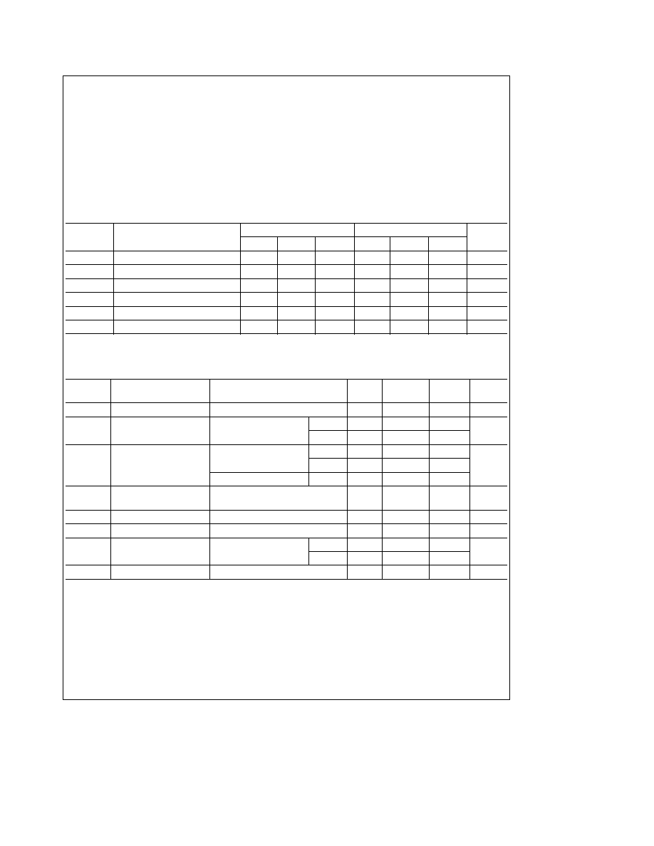
Recommended Operating Conditions
Symbol
Parameter
DM54LS155
DM74LS155
Units
Min
Nom
Max
Min
Nom
Max
V
CC
Supply Voltage
4 5
5
5 5
4 75
5
5 25
V
V
IH
High Level Input Voltage
2
2
V
V
IL
Low Level Input Voltage
0 7
0 8
V
V
OH
High Level Output Current
b
0 4
b
0 4
mA
I
OL
Low Level Output Current
4
8
mA
T
A
Free Air Operating Temperature
b
55
125
0
70
C
'LS155 Electrical Characteristics
over recommended operating free air temperature range (unless otherwise noted)
Symbol
Parameter
Conditions
Min
Typ
Max
Units
(Note 1)
V
I
Input Clamp Voltage
V
CC
e
Min I
I
e b
18 mA
b
1 5
V
V
OH
High Level Output
V
CC
e
Min I
OH
e
Max
DM54
2 5
3 4
V
Voltage
V
IL
e
Max V
IH
e
Min
DM74
2 7
3 4
V
OL
Low Level Output
V
CC
e
Min I
OL
e
Max
DM54
0 25
0 4
Voltage
V
IL
e
Max V
IH
e
Min
DM74
0 35
0 5
V
I
OL
e
4 mA V
CC
e
Min
DM74
0 25
0 4
I
I
Input Current
Max
V
CC
e
Max V
I
e
7V
0 1
mA
Input Voltage
I
IH
High Level Input Current
V
CC
e
Max V
I
e
2 7V
20
m
A
I
IL
Low Level Input Current
V
CC
e
Max V
I
e
0 4V
b
0 36
mA
I
OS
Short Circuit
V
CC
e
Max
DM54
b
20
b
100
mA
Output Current
(Note 2)
DM74
b
20
b
100
I
CC
Supply Current
V
CC
e
Max (Note 3)
6 1
10
mA
Note 1
All typicals are at V
CC
e
5V T
A
e
25 C
Note 2
Not more than one output should be shorted at a time and the duration should not exceed one second
Note 3
I
CC
is measured with all outputs open A B and C1 inputs at 4 5V and C2 G1 and G2 inputs grounded
2

'LS155 Switching Characteristics
at V
CC
e
5V and T
A
e
25 C (See Section 1 for Test Waveforms and Output Load)
From (Input)
R
L
e
2 kX
Symbol
Parameter
To (Output)
C
L
e
15 pF
C
L
e
50 pF
Units
Min
Max
Min
Max
t
PLH
Propagation Delay Time
A B C2 G1
18
22
ns
Low to High Level Output
or G2 to Y
t
PHL
Propagation Delay Time
A B C2 G1
27
35
ns
High to Low Level Output
or G2 to Y
t
PLH
Propagation Delay Time
A or B
18
24
ns
Low to High Level Output
to Y
t
PHL
Propagation Delay Time
A or B
27
35
ns
High to Low Level Output
to Y
t
PLH
Propagation Delay Time
C1
20
24
ns
Low to High Level Output
to Y
t
PHL
Propagation Delay Time
C1
27
35
ns
High to Low Level Output
to Y
Recommended Operating Conditions
Symbol
Parameter
DM54LS156
DM74LS156
Units
Min
Nom
Max
Min
Nom
Max
V
CC
Supply Voltage
4 5
5
5 5
4 75
5
5 25
V
V
IH
High Level Input Voltage
2
2
V
V
IL
Low Level Input Voltage
0 7
0 8
V
V
OH
High Level Output Voltage
5 5
5 5
V
I
OL
Low Level Output Current
4
8
mA
T
A
Free Air Operating Temperature
b
55
125
0
70
C
'LS156 Electrical Characteristics
over recommended operating free air temperature range (unless otherwise noted)
Symbol
Parameter
Conditions
Min
Typ
Max
Units
(Note 1)
V
I
Input Clamp Voltage
V
CC
e
Min I
I
e b
18 mA
b
1 5
V
I
CEX
High Level Output
V
CC
e
Min V
O
e
5 5V
100
m
A
Current
V
IL
e
Max V
IH
e
Min
V
OL
Low Level Output
V
CC
e
Min I
OL
e
Max
DM54
0 25
0 4
Voltage
V
IL
e
Max V
IH
e
Min
DM74
0 35
0 5
V
I
OL
e
4 mA V
CC
e
Min
DM74
0 25
0 4
I
I
Input Current
Max
V
CC
e
Max V
I
e
7V
0 1
mA
Input Voltage
I
IH
High Level Input Current
V
CC
e
Max V
I
e
2 7V
20
m
A
I
IL
Low Level Input Current
V
CC
e
Max V
I
e
0 4V
b
0 36
mA
I
CC
Supply Current
V
CC
e
Max (Note 2)
6 1
10
mA
Note 1
All typicals are at V
CC
e
5V T
A
e
25 C
Note 2
I
CC
is measured with all outputs open A B and C1 inputs at 4 5V and C2 G1 and G2 grounded
3

'LS156 Switching Characteristics
at V
CC
e
5V and T
A
e
25 C (See Section 1 for Test Waveforms and Output Load)
From (Input)
R
L
e
2 kX
Symbol
Parameter
To (Output)
C
L
e
15 pF
C
L
e
50 pF
Units
Min
Max
Min
Max
t
PLH
Propagation Delay Time
A B C2 G1
28
53
ns
Low to High Level Output
or G2 to Y
t
PHL
Propagation Delay Time
A B C2 G1
33
43
ns
High to Low Level Output
or G2 to Y
t
PLH
Propagation Delay Time
A or B
28
53
ns
Low to High Level Output
to Y
t
PHL
Propagation Delay Time
A or B
33
43
ns
High to Low Level Output
to Y
t
PLH
Propagation Delay Time
C1
28
53
ns
Low to High Level Output
to Y
t
PHL
Propagation Delay Time
C1
34
43
ns
High to Low Level Output
to Y
Logic Diagram
TL F 6395 � 2
4

5

Physical Dimensions
inches (millimeters)
Ceramic Leadless Chip Carrier (E)
Order Number 54LS155LMQB
NS Package Number E20A
16-Lead Ceramic Dual-In-Line Package (J)
Order Number 54LS155DMQB 54LS156DMQB DM54LS155J or DM54LS156J
NS Package Number J16A
6
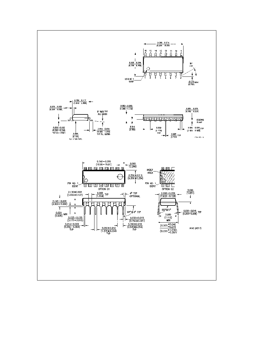
Physical Dimensions
inches (millimeters) (Continued)
16-Lead Small Outline Molded Package (M)
Order Number DM74LS155M or DM74LS156M
NS Package Number M16A
16-Lead Molded Dual-In-Line Package (N)
Order Number DM74LS155N or DM74LS156N
NS Package Number N16E
7
54LS155DM54LS155DM74LS155
54LS156DM54LS156DM74LS156
Dual
2-Line
to
4-Line
DecodersDemultiplexers
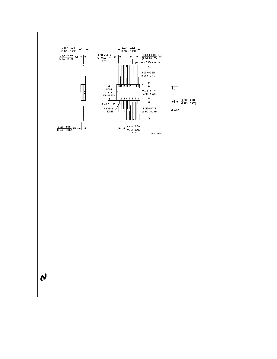
Physical Dimensions
inches (millimeters) (Continued)
16-Lead Ceramic Flat Package (W)
Order Number 54LS155FMQB 54LS156FMQB DM54LS155W or DM54LS156W
NS Package Number W16A
LIFE SUPPORT POLICY
NATIONAL'S PRODUCTS ARE NOT AUTHORIZED FOR USE AS CRITICAL COMPONENTS IN LIFE SUPPORT
DEVICES OR SYSTEMS WITHOUT THE EXPRESS WRITTEN APPROVAL OF THE PRESIDENT OF NATIONAL
SEMICONDUCTOR CORPORATION As used herein
1 Life support devices or systems are devices or
2 A critical component is any component of a life
systems which (a) are intended for surgical implant
support device or system whose failure to perform can
into the body or (b) support or sustain life and whose
be reasonably expected to cause the failure of the life
failure to perform when properly used in accordance
support device or system or to affect its safety or
with instructions for use provided in the labeling can
effectiveness
be reasonably expected to result in a significant injury
to the user
National Semiconductor
National Semiconductor
National Semiconductor
National Semiconductor
Corporation
Europe
Hong Kong Ltd
Japan Ltd
1111 West Bardin Road
Fax (a49) 0-180-530 85 86
13th Floor Straight Block
Tel 81-043-299-2309
Arlington TX 76017
Email cnjwge tevm2 nsc com
Ocean Centre 5 Canton Rd
Fax 81-043-299-2408
Tel 1(800) 272-9959
Deutsch Tel (a49) 0-180-530 85 85
Tsimshatsui Kowloon
Fax 1(800) 737-7018
English
Tel (a49) 0-180-532 78 32
Hong Kong
Fran ais Tel (a49) 0-180-532 93 58
Tel (852) 2737-1600
Italiano
Tel (a49) 0-180-534 16 80
Fax (852) 2736-9960
National does not assume any responsibility for use of any circuitry described no circuit patent licenses are implied and National reserves the right at any time without notice to change said circuitry and specifications