TL F 11407
DP83265A
BSI-2
Device
(FDDI
System
Interface)
PRELIMINARY
November 1994
DP83265A BSI-2
TM
Device
(FDDI System Interface)
General Description
The DP83265A BSI-2 device implements an interface be-
tween the National FDDI BMAC
TM
device and a host sys-
tem It provides a multi-frame MAC-level interface to one or
more MAC Users It is an enhanced version of the DP83265
BSI
TM
device
The BSI-2 device accepts MAC User requests to receive
and transmit multiple frames (Service Data Units) On re-
ception (Indicate) it receives the byte stream from the
BMAC device packs it into 32-bit words and writes it to
memory On transmission (Request) it unpacks the 32-bit
wide memory data and sends it a byte at a time to the
BMAC device The host software and the BSI-2 device com-
municate via registers memory-resident descriptors and an
attention notify scheme using clustered interrupts
Features
Y
Fully software and pin compatible with the original BSI
Y
Over 2 kbytes of on-chip FIFO
Y
Operates from 12 5 MHz to 33 MHz synchronously with
host system
Y
Provides Address bit swapping capability
Y
Reduces interface logic for SBus adapters
Y
32-bit wide Address Data path with byte parity
Y
Programmable transfer burst sizes of 4 or 8 32-bit
words
Y
Interfaces to DRAMs or directly to system bus
Y
2 Output and 3 Input Channels
Y
Supports Header Info splitting
Y
Bridging support
Y
Programmable Big or Little Endian alignment
Y
Full Duplex data path
Y
Receive frame filtering services
Block Diagram
TL F 11407 � 1
FIGURE 1-1 FDDI Chip Set
TRI-STATE
is a registered trademark of National Semiconductor Corporation
BMAC
TM
BSI
TM
BSI-2
TM
CDD
TM
CRD
TM
and PLAYER
TM
are trademarks of National Semiconductor Corporation
C1995 National Semiconductor Corporation
RRD-B30M105 Printed in U S A

Table of Contents
1 0 FDDI CHIP SET OVERVIEW
2 0 GENERAL FEATURES
2 1 32-Bit Address Data Path to Host Memory
2 2 Multi-Channel Architecture
2 3 Support for Header Info Splitting
2 4 MAC Bridging Support
2 5 Address Bit Swapping
2 6 Status Batching Services
2 7 Receive Frame Filtering Services
2 8 Two Timing Domains
2 9 Clustered Interrupts
3 0 ARCHITECTURE DESCRIPTION
3 1 Interfaces
3 2 Data Structures
3 3 Service Engine
4 0 FUNCTIONAL DESCRIPTION
4 1 Overview
4 2 Operation
4 3 External Matching Interface
4 4 Bus Interface Unit
5 0 CONTROL INFORMATION
5 1 Overview
5 2 Operation Registers
5 3 Pointer RAM Registers
5 4 Limit RAM Registers
5 5 Descriptors
5 6 Operating Rules
5 7 Pointer RAM Register Descriptions
5 8 Limit RAM Register Descriptions
6 0 SIGNAL DESCRIPTIONS
Pin Table and Pin Diagram
6 1 Control Interface
6 2 BMAC Device Indicate Interface
6 3 BMAC Device Request Interface
6 4 ABus Interface
6 5 Electrical Interface
7 0 ELECTRICAL CHARACTERISTICS
7 1 Absolute Maximum Ratings
7 2 Recommended Operating Conditions
7 3 DC Electrical Characteristics
7 4 AC Electrical Characteristics
2

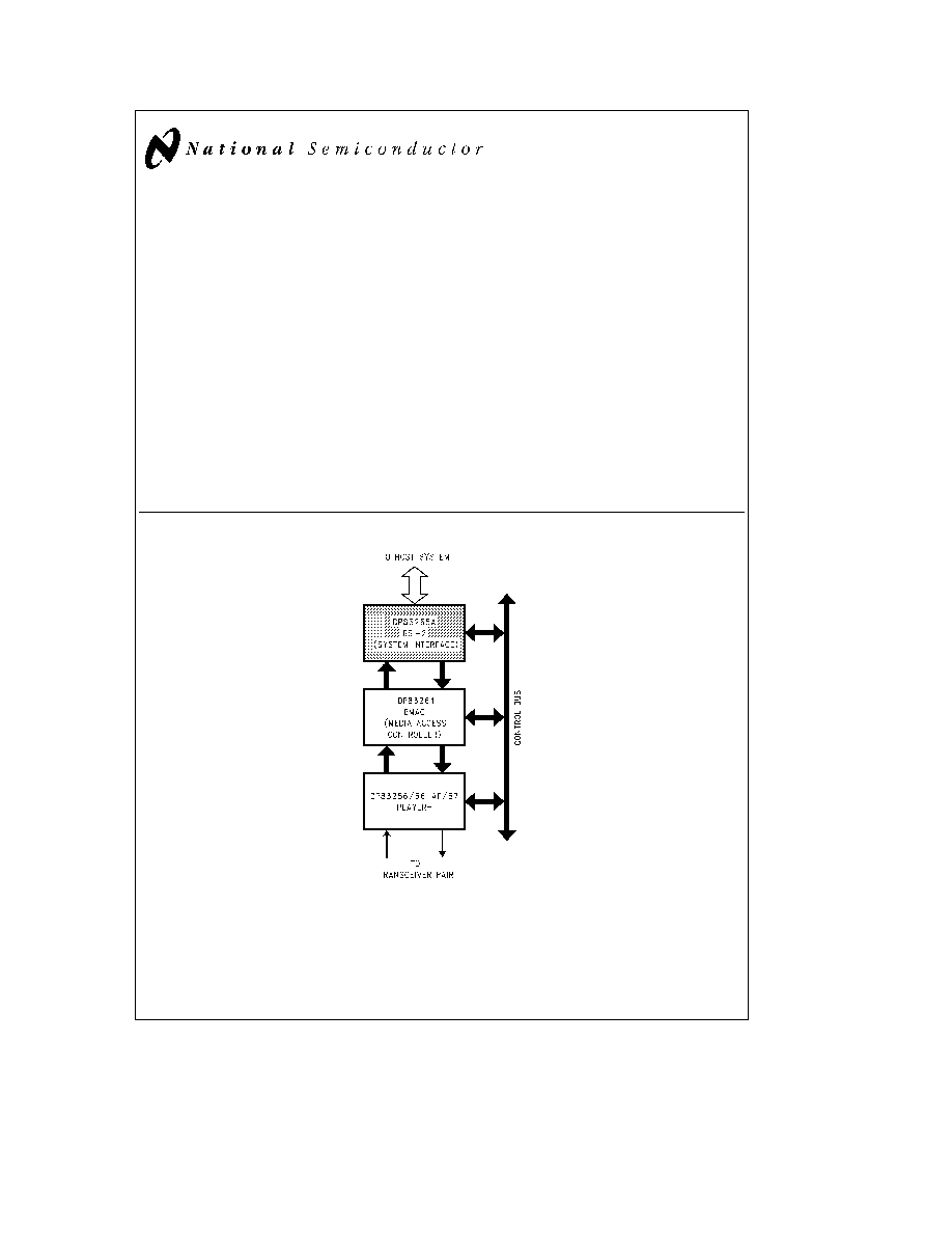
1 0 FDDI Chip Set Overview
National Semiconductor's FDDI chip set includes the three
components as shown in
Figure 1-1 For more information
about the other devices in the chip set consult the appropri-
ate datasheets and application notes
DP83256 56-AP 57 PLAYER
a
Device Physical Layer Controller
The PLAYER
a
device implements the Physical Layer
(PHY) protocol as defined by the ANSI FDDI PHY X3T9 5
standard
Features
Y
Single chip FDDI Physical Layer (PHY) solution
Y
Integrated Digital Clock Recovery Module provides en-
hanced tracking and greater lock acquisition range
Y
Integrated Clock Generation Module provides all neces-
sary clock signals for an FDDI system from an external
12 5 MHz reference
Y
Alternate PMD Interface (DP83256-AP 57) supports
UTP twisted pair FDDI PMDs with no external clock re-
covery or clock generation functions required
Y
No External Filter Components
Y
Connection Management (CMT) Support (LEM TNE
PC
React CF
React Auto Scrubbing)
Y
Full on-chip configuration switch
Y
Low Power CMOS-BIPOLAR design using a single 5V
supply
Y
Full duplex operation with through parity
Y
Separate management interface (Control Bus)
Y
Selectable Parity on PHY-MAC Interface and Control
Bus Interface
Y
Two levels of on-chip loopback
Y
4B 5B encoder decoder
Y
Framing logic
Y
Elasticity Buffer Repeat Filter and Smoother
Y
Line state detector generator
Y
Supports single attach stations
dual attach stations
and concentrators with no external logic
Y
DP83256 56-AP for SAS DAS single path stations
Y
P83257 for SAS DAS single dual path stations
In addition the DP83257 contains the additional PHY
Da-
ta request and PHY
Data indicate ports required for con-
centrators and dual attach dual path stations
DP83261 BMAC Device Media
Access Controller
The BMAC device implements the Timed Token Media Ac-
cess Control protocol defined by the ANSI FDDI X3T9 5
MAC Standard
Features
Y
All of the standard defined ring service options
Y
Full duplex operation with through parity
Y
Supports all FDDI Ring Scheduling Classes (Synchro-
nous Asynchronous etc )
Y
Supports Individual Group Short Long and External
Addressing
Y
Generates Beacon Claim and Void frames internally
Y
Extensive ring and station statistics gathering
Y
Extensions for MAC level bridging
Y
Separate management port that is used to configure
and control operation
Y
Multi-frame streaming interface
DP83265A BSI-2 Device System
Interface
The BSI-2 Device implements an interface between the
BMAC device and a host system
Features
Y
Fully software and pin compatible with the original BSI
device
Y
Over 2 kbytes of on-chip FIFO
Y
Operates from 12 5 MHz to 33 MHz synchronously with
host system
Y
Provides Address bit swapping capability
Y
Reduces interface logic for SBus adapters
Y
32-bit wide Address Data path with byte parity
Y
Programmable transfer burst sizes of 4 or 8 32-bit
words
Y
Interfaces to DRAMs or directly to system bus
Y
2 Output and 3 Input Channels
Y
Supports Header Info splitting
Y
Bridging support
Y
Programmable Big or Little Endian alignment
Y
Full Duplex data path
Y
Receive frame filtering services
3

2 0 General Features
The BSI-2 device implements a system interface for the
FDDI BMAC Device It is designed to provide a high-per-
formance low-cost interface for a variety of hosts
On the system side the BSI-2 device provides a simple yet
powerful bus interface and memory management scheme to
maximize system efficiency It is capable of interfacing to a
variety of host busses environments The BSI-2 device pro-
vides a 32-bit wide multiplexed address data interface
which can be configured to share a system bus to main
memory or communicate via external shared memory The
system interface supports virtual addressing using fixed-size
pages
On the network side the BSI-2 device performs many func-
tions which greatly simplify the interface to the BMAC de-
vice and provides many services which simplify network
management and increase system performance and reliabil-
ity The BSI-2 device is capable of batching confirmation
and Indication status filtering out MAC frames with the
same Information field and VOID frames and performing
network monitoring functions
2 1 32-BIT ADDRESS DATA PATH TO HOST MEMORY
The BSI-2 device provides a 32-bit wide synchronous multi-
plexed address data interface which permits interfacing to
a standard multi-master system bus operating from
12 5 MHz to 33 MHz or to local memory using Big or Little
Endian byte ordering The memory may be static or dynam-
ic For maximum performance the BSI-2 device utilizes
burst mode transfers with four or eight 32-bit words to a
burst To assist the user with the burst transfer capability
the three bits of the address which cycle during a burst are
output demultiplexed Maximum burst speed is one 32-bit
word per clock but slower speeds may be accommodated
by inserting wait states
The BSI-2 device can operate within any combination of
cached non-cached paged or non-paged memory environ-
ments To provide this capability all data structures are con-
tained within a page and bus transactions never cross a
page The BSI-2 device performs all bus transactions within
aligned blocks to ease the interface to a cached environ-
ment
2 2 MULTI-CHANNEL ARCHITECTURE
The BSI-2 device provides three Input Channels and two
Output Channels which are designed to operate indepen-
dently and concurrently They are separately configured by
the user to manage the reception or transmission of a par-
ticular kind of frame (for example synchronous frames
only)
2 3 SUPPORT FOR HEADER INFO SPLITTING
In order to support high performance protocol processing
the BSI-2 device can be programmed to split the header
and information portions of (non-MAC SMT) frames be-
tween two Indicate Channels Frame bytes from the Frame
Control field (FC) up to the user-defined header length are
copied onto Indicate Channel 1 and the remaining bytes
(Info) are copied onto Indicate Channel 2 This is useful for
separating protocol headers and data It also allows them to
be stored in different regions of memory which can prevent
unnecessary copying In addition a protocol monitor appli-
cation may decide to copy only the header portion of each
frame
2 4 MAC BRIDGING SUPPORT
Support for bridging and monitoring applications is provided
by the Internal External Sorting Mode All frames matching
the external address (frames requiring bridging) are sorted
onto Indicate Channel 2 MAC and SMT frames matching
the internal (BMAC device) address are sorted onto Indicate
Channel 0 and all other frames matching the BMAC de-
vice's internal address (short or long) are sorted onto Indi-
cate Channel 1
2 5 ADDRESS BIT SWAPPING
The BSI-2 contains the necessary logic for swapping the
address fields within each frame between FDDI and IEEE
Canonical bit order This involves a bit reversal within each
byte of the address field (e g 08-00-17-C2-A1-03 would be-
come 10 00 E8 43 85 C0) This option is selectable on a per
channel basis and is supported on all channels both trans-
mit and receive This is useful for bridging FDDI to Ethernet
or for swapping addresses for higher level protocols
2 6 STATUS BATCHING SERVICES
The BSI-2 device provides status for transmitted and re-
ceived frames Interrupts to the host are generated only at
status breakpoints which are defined by the user on a per
Channel basis Breakpoints are selected when the Channel
is configured for operation To allow batching the BSI-2 pro-
vides a status option called Tend which causes the device
to generate a single Confirmation Message Descriptor
(CNF) for one or more Request Descriptors (REQs)
The BSI-2 device further reduces host processing time by
separating received frame status from the received data
This allows the CPU to scan quickly for errors when decid-
ing whether further processing should be done on received
frames If the status were embedded in the data stream all
the data would need to be read contiguously to find the
Status Indicator
2 7 RECEIVE FRAME FILTERING SERVICES
To increase performance and reliability the BSI-2 device
can be programmed to filter out identical MAC (same FC
and Info field) or SMT frames received from the ring VOID
frames are filtered out automatically Filtering unnecessary
frames reduces the fill rate of the Indicate FIFO reduces
CPU frame processing time and avoids unnecessary mem-
ory bus transactions
2 8 TWO TIMING DOMAINS
To provide maximum performance and system flexibility the
BSI-2 device utilizes two independent clocks one for the
MAC (ring) Interface and one for the system memory bus
The BSI-2 device provides a fully synchronized interface be-
tween these two timing domains
2 9 CLUSTERED INTERRUPTS
The BSI-2 device can be operated in a polled or interrupt-
driven environment The BSI-2 device provides the ability to
generate attentions (interrupts) at group boundaries Some
boundaries are pre-defined in hardware others are defined
by the user when the Channel is configured This interrupt
scheme significantly reduces the number of interrupts to the
host thus reducing host processing overhead
4
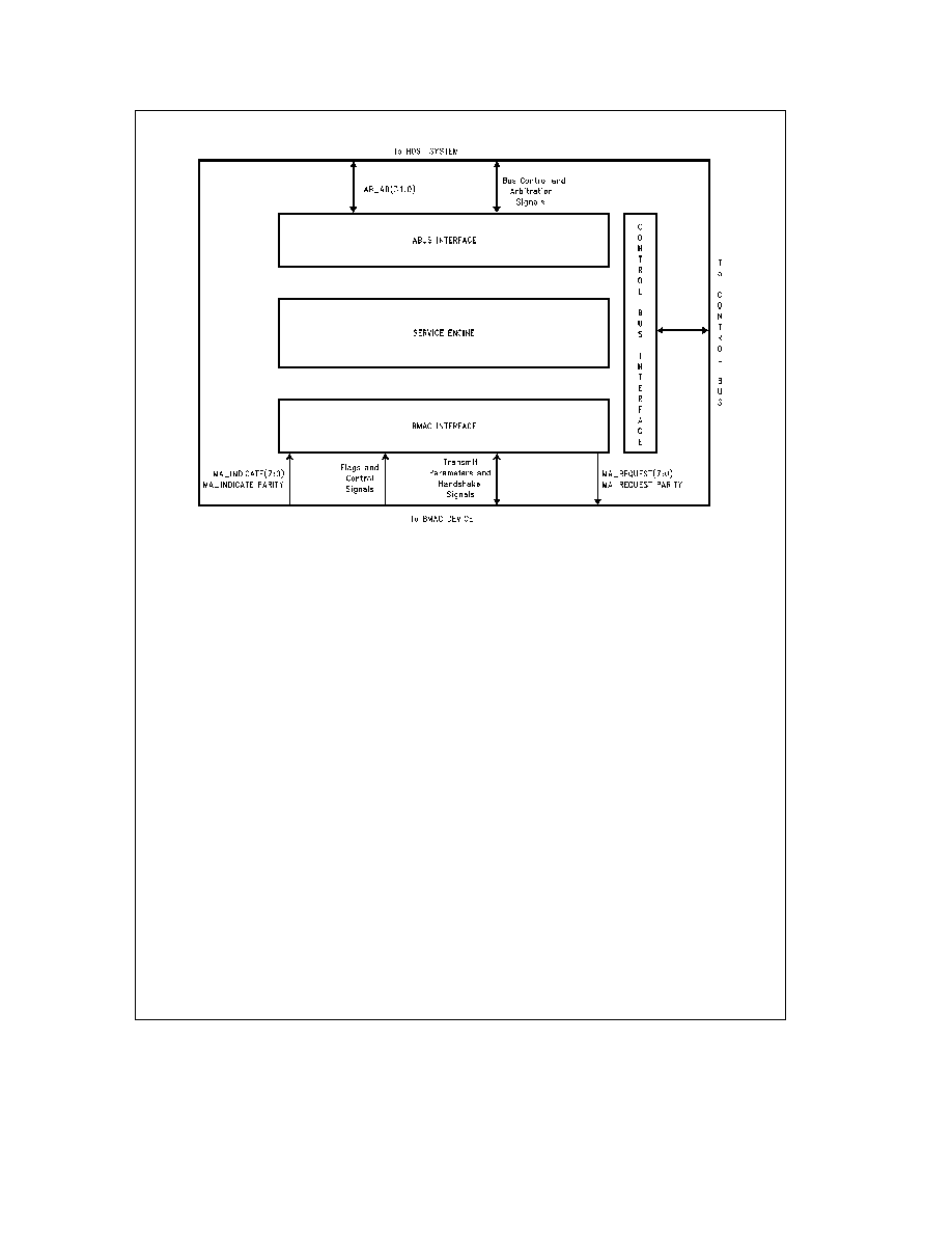
3 0 Architecture Description
TL F 11407 � 2
FIGURE 3-1 BSI-2 Device Interfaces
The BSI-2 device is composed of three interfaces and the
Service Engine
The three interfaces are the BMAC device the ABus and
the Control Bus Interfaces They are used to connect the
BSI-2 device to the BMAC device Host System and exter-
nal Control Bus respectively
The Service Engine manages the operation of the BSI-2
device
3 1 INTERFACES
The BSI-2 device connects to external components via
three interfaces the BMAC device Interface the ABus Inter-
face and the Control Bus Interface (see
Figure 3-1 )
3 1 1 BMAC Device Interface
The BSI-2 device connects to the BMAC device via the
MA
Indicate (receive) and MA
Request (transmit) Inter-
faces as shown in
Figure 3-1
Received Data is transferred from the BMAC device to the
BSI-2 device via the MA
Indicate Interface The MA
Indi-
cate Interface consists of a parity bit (odd parity) and byte-
wide data along with flag and control signals
Transmit Data is transferred from the BSI-2 device to the
BMAC device via the MA
Request Interface The MA
Re-
quest Interface consists of a parity bit (odd parity) and byte-
wide data along with flag and control signals
3 1 2 ABus Interface
The BSI-2 device connects to the Host System via the ABus
Interface The ABus Interface consists of four bits of parity
(odd parity) and 32 bits of multiplexed address and data
along with transfer control and bus arbitration signals
3 1 3 Control Bus Interface
The Control Bus Interface connects the BSI-2 device to the
external Control Bus
The Control Bus Interface is separate from the BMAC de-
vice and ABus Interfaces to allow independent operation of
the Control Bus
The host uses the Control Bus to access the BSI-2 device's
internal registers and to manage the attention notify logic
3 2 DATA STRUCTURES
3 2 1 Data Types
The architecture of the BSI-2 device defines two basic kinds
of objects Data Units and Descriptors A Data Unit is a
group of contiguous bytes which forms all or part of a frame
A Descriptor is a two-word (64-bit) control object that pro-
vides addressing information and control status information
about BSI-2 device operations
Data and Descriptor objects may consist of one or more
parts where each part is contiguous and wholly contained
within a memory page Descriptor pages are selectable as
all 1 kbytes or all 4 kbytes Data Units are described by
Descriptors with a pointer and a count A single Data Unit
may not cross a 4k boundary All Descriptors may be
marked as First Middle Last or Only Thus multiple De-
scriptors may be combined to describe a single entity (i e
Frame) A single-part object consists of one Only Part a
multiple-part object consists of one First Part zero or more
Middle
Parts and one Last Part In Descriptor names the
object part is denoted in a suffix preceded by a dot Thus
an Input Data Unit Descriptor (IDUD) which describes the
last Data Unit of a frame received from the ring is called an
IDUD Last
5