TL F 11498
DP83905
ATLANTIC
AT
Local
Area
Network
Twisted-Pair
Interface
Controller
PRELIMINARY
November 1995
DP83905 AT LANTIC
TM
AT Local Area Network Twisted-Pair
Interface Controller
General Description
The AT LANTIC AT Local Area Network Twisted-pair Inter-
face Controller is a CMOS VLSI device designed for easy
implementation of CSMA CD local area networks
Unique to the AT LANTIC is the integration of the entire bus
interface for PC-AT
ISA (Industry Standard Architecture)
bus based systems Hardware and software selectable op-
tions allow the AT LANTIC's bus interface to be configured
software compatible to either an NE2000 or Ethercard
PLUS16
TM
All bus drivers and control logic are integrated
to reduce board cost and area
Supported
network
interfaces
include
10BASE5
or
10BASE2 Ethernet via an external transciever connected to
its AUI port and Twisted-pair Ethernet (10BASE-T) using
the on-board transceiver The AT LANTIC provides the
Ethernet Media Access Control (MAC) Encode-Decode
(ENDEC) with an AUI interface and 10BASE-T transceiver
functions in accordance with the IEEE 802 3 standards
The AT LANTIC's integrated 10BASE-T transceiver fully
complies with the IEEE standard This functional block incor-
porates the receiver transmitter collision heartbeat Ioop-
back jabber and link integrity blocks as defined in the stan-
dard The transceiver when combined with equalization re-
sistors transmit receive filters and pulse transformers pro-
vides a complete physical interface from the AT LANTIC
Controller's ENDEC module and the twisted pair medium
(Continued)
Features
Y
Controller and integrated bus interface solution for IEEE
802 3 10BASE5 10BASE2 and 10BASE-T
Y
Software compatible with
Novell 's NE2000 Plus indus-
try standard Ethernet Adapters
Y
Selectable buffer memory size
Y
No external bus logic or drivers
Y
Integrated controller ENDEC and transceiver
Y
Full IEEE 802 3 AUI interface
Y
Single 5V supply
10BASE-T TRANSCEIVER MODULE
Y
Integrates transceiver functionality
Transmitter and receiver functions
Collision detect heartbeat and jabber
Selectable link integrity test or link disable
Polarity Detection Correction
ENDEC MODULE
Y
10 Mbit s Manchester encoding decoding
Y
Squelch on receive and collision pairs
MAC CONTROLLER MODULE
Y
Software compatible with DP8390 DP83901 DP83902
Y
Efficient buffer management implementation
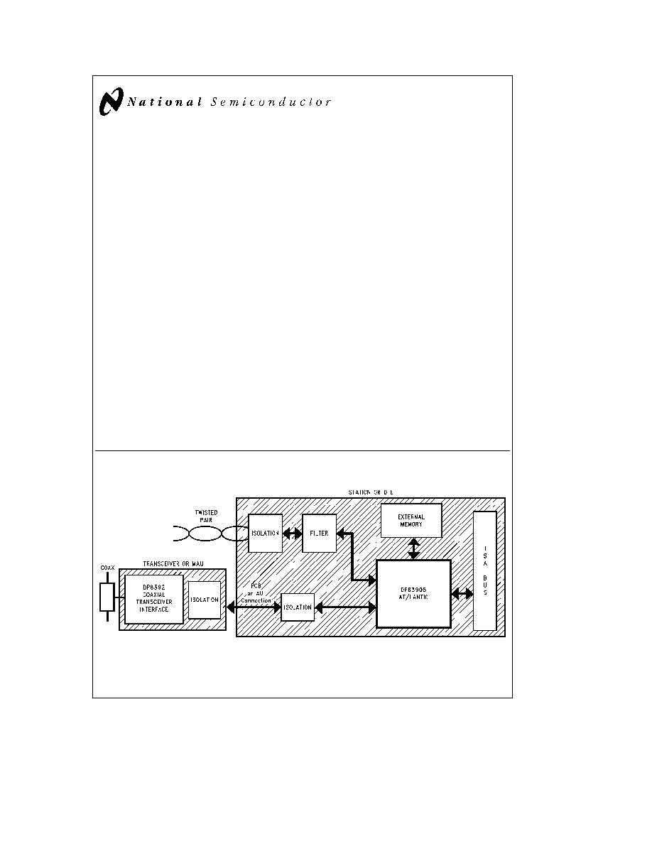
1 0 System Diagram
TL F 11498 � 1
TRI-STATE
is a registered trademark of National Semiconductor Corporation
AT LANTIC
TM
is a trademark of National Semiconductor Corporation
PC-AT
is a registered trademark of International Business Machines Corp
Novell
is a registered trademark of Novell Inc
EtherCard PLUS
TM
and EtherCard PLUS 16
TM
are trademarks of Standard Microsystems Corp
C1995 National Semiconductor Corporation
RRD-B30M115 Printed in U S A

General Description
(Continued)
The integrated ENDEC module allows Manchester encod-
ing and decoding via a differential transceiver and phase
lock Ioop decoder at 10 Mbit sec Also included are a colli-
sion detect translator and diagnostic loopback capability
The ENDEC module interfaces directly to the transceiver
module and also provides a fully IEEE compliant AUI (At-
tachment Unit Interface) for connection to other media
transceivers
The Media Access Control function which is provided by the
Network Interface Control module (NIC) provides simple
and efficient packet transmission and reception control by
means of off-board memory which can be accessed either
through an I O port or mapped into the system memory
AT LANTIC Controller provides a comprehensive solution
for 10BASE-T IEEE 802 3 networks Due to the inherent
constraints of CMOS processing isolation is required at the
AUI differential signal interface for 10BASE5 and 10BASE2
applications
Table of Contents
1 0 SYSTEM DIAGRAM
1 1 Connection Diagram
2 0 PIN DESCRIPTION
3 0 SIMPLIFIED APPLICATION DIAGRAM
4 0 FUNCTIONAL DESCRIPTION
4 1 Bus Interface Block
4 2 Power on RESET operation
4 3 EEPROM Operation
4 4 Jumpered and Jumperless Operation Support
4 5 Low Power Operation
4 6 Boot PROM Operation
4 7 DP8390 Core (Network Interface Controller)
4 8 Twisted Pair Interface Module
4 9 Encoder Decoder (ENDEC) Module
5 0 REGISTER DESCRIPTIONS
5 1 Configuration Registers
5 2 Shared Memory Mode Control Registers
5 3 NIC Core Registers
5 4 DP8390 Core DMA Registers
6 0 OPERATION OF AT LANTIC CONTROLLER
6 1 Transmit Receive Packet Encapsulation
Decapsulation
6 2 Buffer Memory Access Control (DMA)
6 3 Packet Reception
6 4 Packet Transmission
6 5 Loopback Diagnostics
6 6 Memory Arbitration and Bus Operation
6 7 Functional Bus Timing
7 0 PRELIMINARY ELECTRICAL CHARACTERISTICS
8 0 PRELIMINARY SWITCHING CHARACTERISTICS
9 0 AC TIMING TEST CONDITIONS
2
1 0 System Diagram
(Continued)
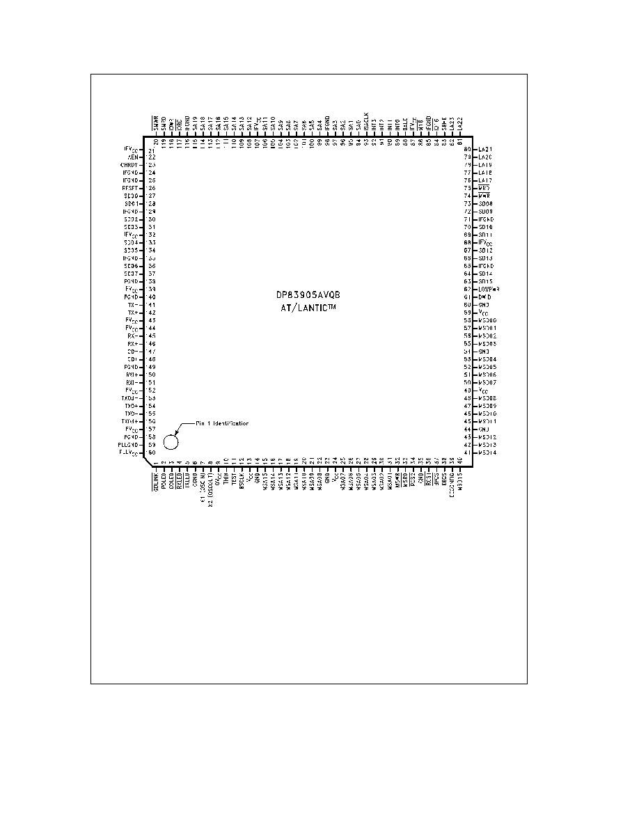
1 1 CONNECTION DIAGRAM
TL F 11498 � 2
Order Number DP83905AVQB
See NS Package Number VUL160A
3
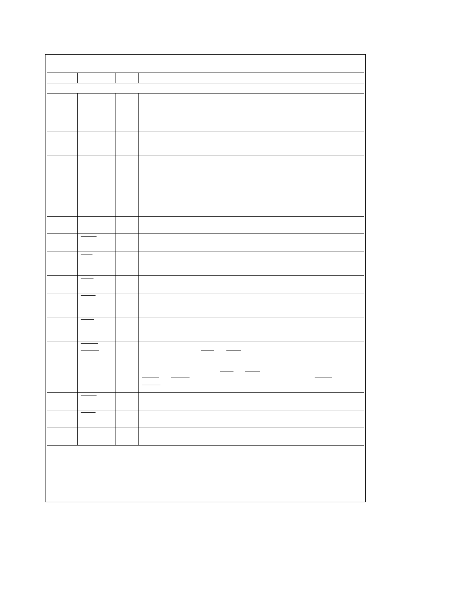
2 0 Pin Description
Pin No
Pin Name
Type
Description
ISA BUS INTERFACE PINS
94�97
SA0�SA1 9
I
LATCHED ADDRESS BUS
Low-order 20 bits of the system's 24 bit address bus
These lines are enabled onto the bus by the system when BALE is high and are
99�106
TTL
Iatched when BALE returns Iow These bits are used to decode accesses to the
108�115
AT LANTIC Controller's I O map and to the boot PROM In addition they are used to
decode accesses to the AT LANTIC Controller's memory in shared memory mode
76�82
LA17�LA23
I
UNLATCHED ADDRESS BUS
High order 7 bits of the 24-bit system address bus
These Iines are valid on the falling edge of BALE These bits are used to decode
TTL
accesses to the AT LANTIC Controller's memory in shared memory mode
127 128
SD0�SD15
I O
SYSTEM DATA BUS
16-bit system data bus Used to transfer data between the
system and the AT LANTIC Controller
130 131
3SH
133 134
136 137
73 72
70 69
67 66
64 63
88
BALE
I
BUS ADDRESS LATCH ENABLE
This signal indicates when the system address
lines are valid
TTL
83
SBHE
I
SYSTEM BUS HIGH ENABLE
This signal indicates that the system expects a
transfer on the upper byte lane
TTL
86
M16
O
16-BIT MEMORY TRANSFER
In 16-bit shared memory mode this signal indicates
that the AT LANTIC Controller has decoded an address within the 128 kbyte space
OCH
that it occupies part of
84
IO16
O
16-BIT I O TRANSFER
In I O mode this signal indicates that the AT LANTIC
Controller is responding to a 16-bit I O access by driving 16-bits of data on the bus
OCH
74
MWR
I
MEMORY WRITE STROBE
Strobe from system to write to AT LANTIC Controller's
memory map
This pin should be connected to allow the CHRDY fix in 16-bit I O mode
TTL
to operate correctly (See Section 6 0)
75
MRD
I
MEMORY READ STROBE
Strobe from system to read from AT LANTIC Controller's
memory map
This pin should be connected to allow the CHRDY fix in 16-bit I O mode
TTL
to operate correctly (See Section 6 0)
119
SMRD
I
LOW MEMORY STROBES
In Memory mode these signals strobe memory transfers
in the same manner as MRD and MWR except that these signals only occur if the
120
SMWR
TTL
access is to the lowest 1 Megabyte This partial address decode means that these
signals can be used in an 8-bit slot to properly decode an access to this area
The
AT LANTIC Controller will use MRD and MWR in 16-bit Memory mode and will use
SMRD and SMWR in Memory mode when DWID is low (8-bit mode) SMRD and
SMWR are also used to access the BOOT PROM
118
IOWR
I
I O WRITE STROBE
Strobe from system to write to the AT LANTIC Controller's I O
map
TTL
117
IORD
I
I O READ STROBE
Strobe from system to read from the AT LANTIC Controller's
I O map
TTL
126
RESET
I
RESET
This signal is output by the system to reset all devices on the bus
TTL
Driver Types are I
e
Input O
e
Output I O
e
Bi-directional Output OCH
e
Open Collector 3SH
e
TRI-STATE Output TTL
e
TTL Compatible AUI
e
Attachment Unit Interface TPI
e
Twisted Pair Interface LED
e
LED Drive MOS
e
CMOS Level Compatible XTAL
e
Crystal
4
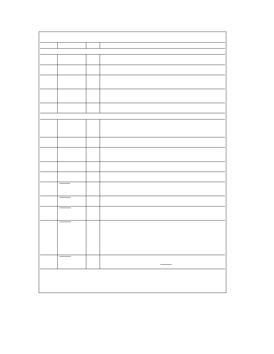
2 0 Pin Description
(Continued)
Pin No
Pin Name
Type
Description
ISA BUS INTERFACE PINS
(Continued)
123
CHRDY
O
CHANNEL READY
This signal is used to insert wait states into system accesses
OCH
122
AEN
I
DMA ACTIVE
This signal indicates that the system's DMA controller has control
of the bus
TTL
89�92
INT0�3
O
INTERRUPT REQUEST
The operation of these 4 outputs is determined by the
Configuration registers They can either be used to directly drive the interrupt lines
3SH
or used as a 3-bit code with a strobe to generate up to 8 interrupts
61
DWID
I
DATA WIDTH
This input specifies whether the AT LANTIC Controller is
interfacing to an 8- or 16-bit ISA bus When high it is in 16-bit mode It has an
MOS
internal pull-down resistor
93
lSACLK
I
ISA CLOCK
Clock from ISA bus This signal is only required if CHRDY timing has
to be altered by changing the CHRDY bit of Configuration Register B
TTL
NETWORK INTERFACE PINS
156�153
TXOd
a
TXO
b
O
TWISTED PAIR TRANSMIT OUTPUTS
These high drive CMOS level outputs
are resistively combined external to the chip to produce a differential output signal
TXO
a
TXOd
b
TPI
with equalization to compensate for Intersymbol Interference (lSI) on the twisted
pair medium
150 151
RXI
a
RXI
b
I
TWISTED PAIR RECEIVE INPUTS
These inputs feed a differential amplifier
which passes valid data to the ENDEC module
TPI
141
TX
b
O
AUI TRANSMIT OUTPUT
Differential driver which sends the encoded data to the
transceiver The outputs are source followers which require 270X pull-down
142
TX
a
AUI
resistors
145
RX
b
I
AUI RECEIVE INPUT
Differential receive input pair from the transceiver
146
RX
a
AUI
147
CD
b
I
AUI COLLISION INPUT
Differential collision pair input from the transceiver
148
CD
a
AUI
5
TXLED
O
TRANSMIT
An open-drain active Iow output It is asserted for approximately
50 ms whenever the AT LANTIC Controller transmits data in either AUI or TPI
LED
modes
4
RXLED
O
RECEIVE
An open-drain active low output It is asserted for approximately 50 ms
whenever receive data is detected in either AUI or TPI mode
LED
3
COLED
O
COLLISION
An open-drain active Iow output It is asserted for approximately 50
ms whenever the AT LANTIC Controller detects a collision in either AUI or TPI
LED
modes
1
GDLNK
O
GOOD LINK
An open-drain active low output This pin operates as an output to
display link integrity status if this function has not been disabled by the GDLNK bit
LED
in Configuration Register B
This output is off if the AT LANTIC Controller is in AUI mode or if link testing is
enabled and the link integrity is bad (i e the twisted pair link has been broken)
This output is on if the AT LANTIC Controller is in Twisted Pair Interface (TPI)
mode link integrity checking is enabled and the link integrity is good (i e the
twisted pair link has not been broken) or if the link testing is disabled
2
POLED
O
POLARITY
An open-drain active low output This signal is normally inactive
When the TPI module detects seven consecutive link pulses or three consecutive
LED
received packets with reversed polarity POLED is asserted
Driver Types are I
e
Input O
e
Output I O
e
Bi-directional Output OCH
e
Open Collector 3SH
e
TRI-STATE Output TTL
e
TTL Compatible AUI
e
Attachment Unit Interface TPI
e
Twisted Pair Interface LED
e
LED Drive MOS
e
CMOS Level Compatible XTAL
e
Crystal
5