TL F 11240
DP83955ADP83956A
LERIC
LitE
Repeater
Interface
Controller
July 1993
DP83955A DP83956A LERIC
TM
LitE Repeater Interface Controller
General Description
The
DP83955 56
LitE
Repeater
Interface
Controller
(LERIC) may be used to implement an IEEE 802 3 multiport
repeater unit It fully satisfies the IEEE 802 3 repeater speci-
fication including the functions defined by the repeater seg-
ment partition and jabber lockup protection state machines
The LERIC has an on-chip phase-locked-loop (PLL) for
Manchester data decoding a Manchester encoder and an
Elasticity Buffer for preamble regeneration
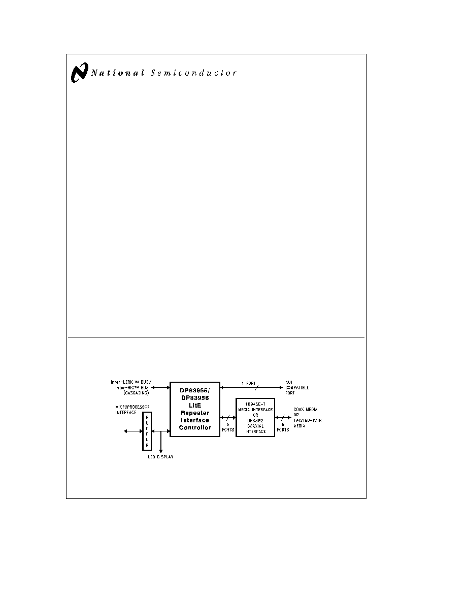
Each LERIC can connect up to 7 cable segments via its
network interface ports One port is fully Attachment Unit
Interface (AUI) compatible and is able to connect to an ex-
ternal Medium Attachment Unit (MAU) using the maximum
length of AUI cable The other 6 ports have integrated
10BASE-T transceivers These transceiver functions may
be bypassed so that the LERIC may be used with external
transceivers such as National's DP8392 coaxial transceiv-
er In addition large repeater units may be constructed by
cascading LERICs together over the Inter-LERIC
TM
or Inter-
RIC
TM
bus
The LERIC is configurable for specific applications It pro-
vides port status information for LED array displays Addi-
tionally the LERIC has a mP interface to provide individual
port status configuration and port enable disable func-
tions
The DP83956 has all the features of the DP83955 except
that two of the bidirectional signals on DP83955 are
changed to unidirectional signals on DP83956 and one
more signal is added to DP83956 to accommodate the addi-
tion of bus transceivers for cascading a greater number of
LERICs in large repeater applications
Specifications enclosed describe both the DP83955 and the
DP83956 unless otherwise noted
For IEEE 802 3 multiport repeater applications which re-
quire conformance to the IEEE 802 3 Draft Repeater Man-
agement options the DP83950 Repeater Interface Control-
ler (RIC
TM
) is recommended especially for highly-managed
hub requirements
Features
Y
Compliant with the IEEE 802 3 Repeater Specification
Y
7 network connections (ports) per chip
Y
Selectable on-chip twisted-pair transceivers
Y
Cascadable for large multiple RIC LERIC hub
applications
Y
Compatible with AUI compliant transceivers
Y
On-chip Elasticity Buffer Manchester encoder and
decoder
Y
Separation Partition state machines for each port
Y
Provides port status information for LED displays
including receive collision partition polarity and link
status
Y
Power-up configuration options
Repeater and Partition
Specifications
Transceiver Interface
Status Display
Processor Operations
Y
Simple processor interface for repeater management
and port disable
Y
Per port receive squelch level selection
Y
CMOS process for low power dissipation
Y
Single 5V supply
1 0 System Diagram
Simple LERIC Hub
TL F 11240 ≠ 1
TRI-STATE
is a registered trademark of National Semiconductor Corporation
Inter-LERIC
TM
Inter-RIC
TM
LERIC
TM
and RIC
TM
are trademarks of National Semiconductor Corporation
PAL
is a registered trademark of and used under license from Advanced Micro Devices Inc
GAL
is a registered trademark of Lattice Semiconductor Corporation
C1995 National Semiconductor Corporation
RRD-B30M105 Printed in U S A

Table of Contents
1 0 SYSTEM DIAGRAM
1
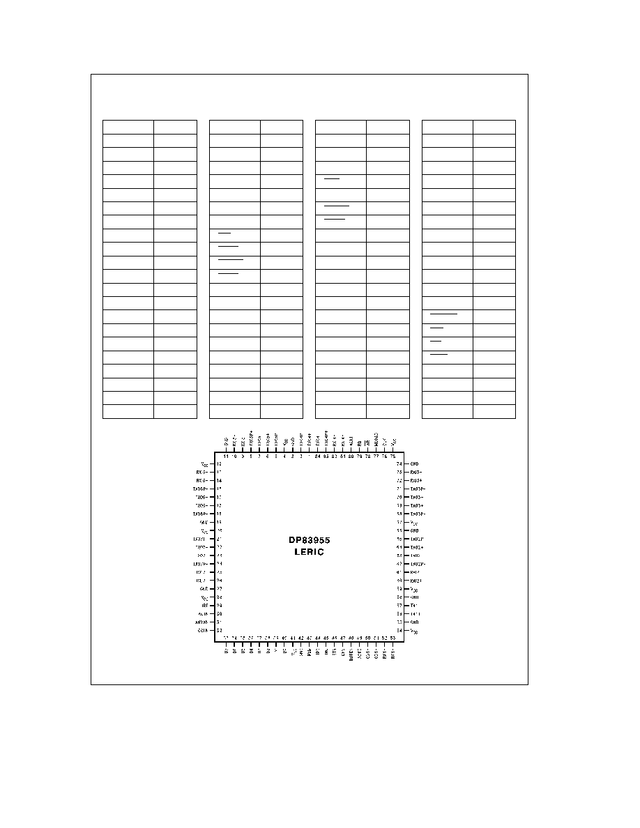
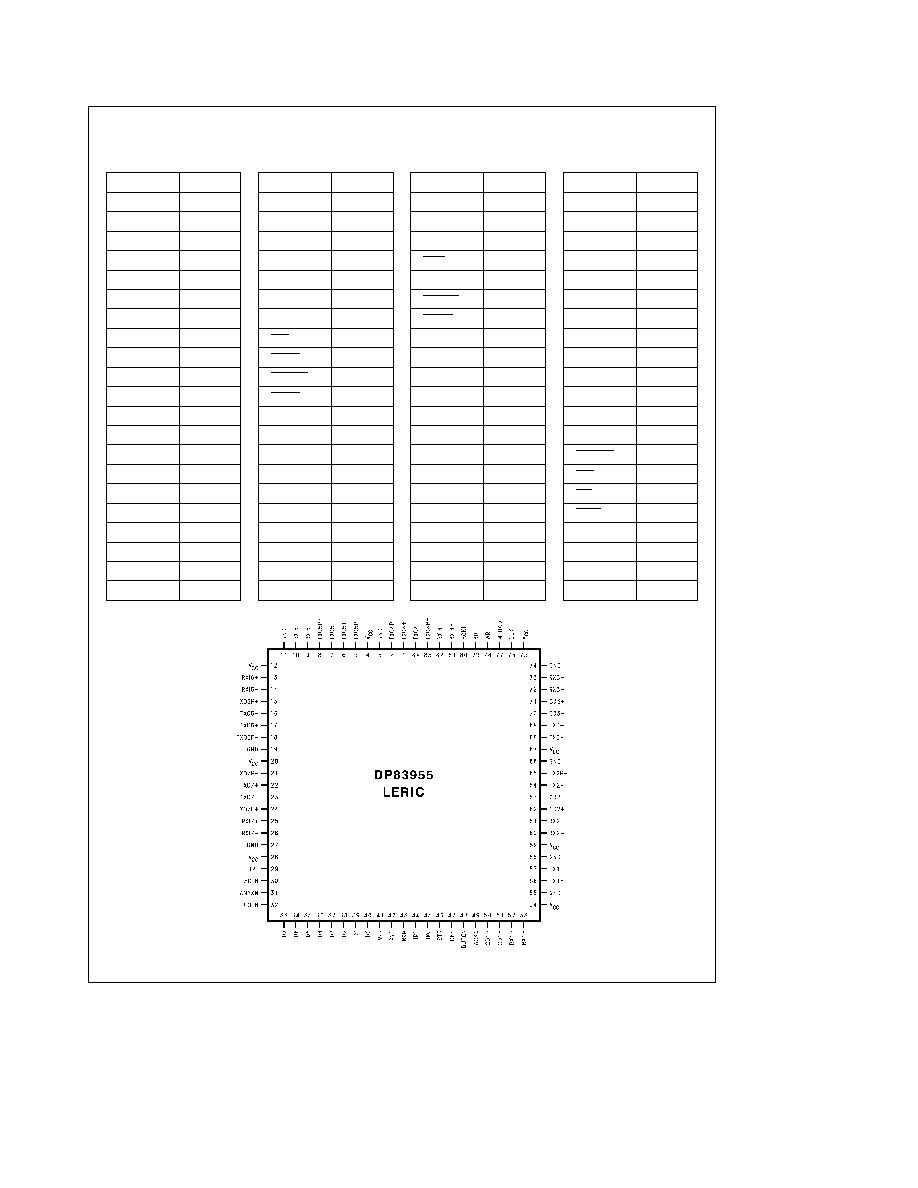
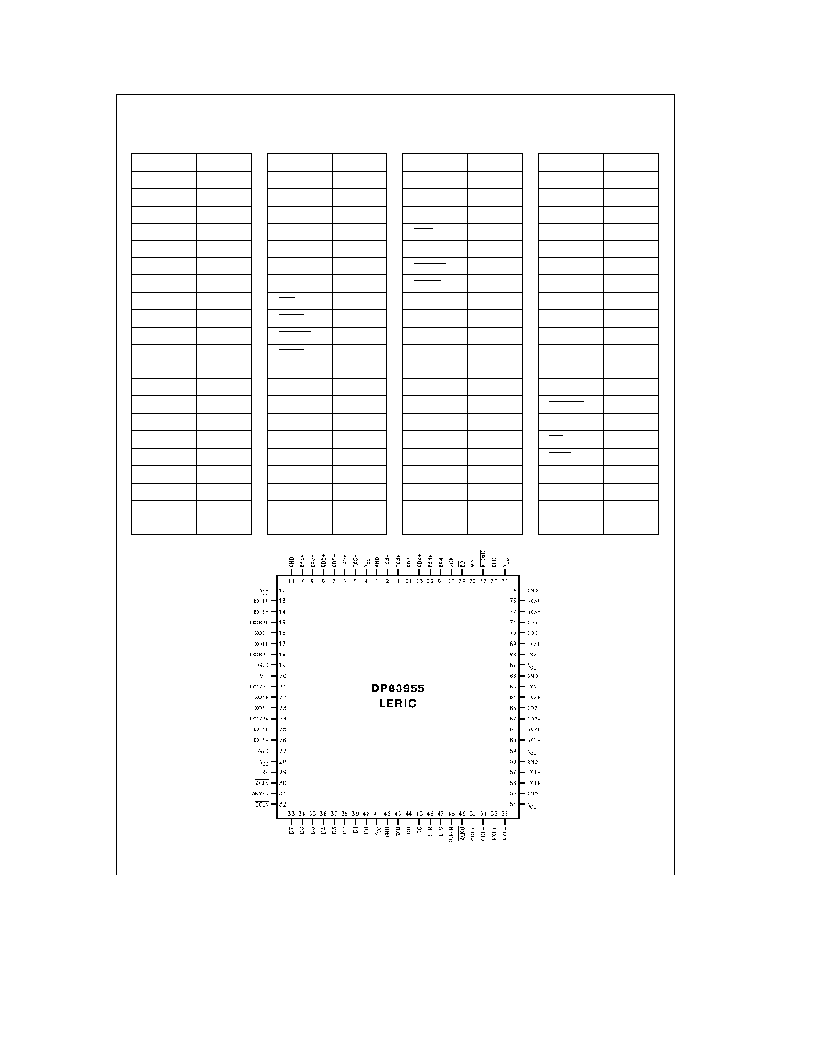
2 0 CONNECTION DIAGRAMS
3
3 0 PIN DESCRIPTION
11
4 0 BLOCK DIAGRAM
15
5 0 FUNCTIONAL DESCRIPTION
17
5 1 Overview of LERIC Functions
17
5 2 Description of Repeater Operations
18
5 3 Examples of Packet Repetition Scenarios
22
5 4 Description of Hardware Connection
for Cascading
29
5 5 Processor and Display Interface
29
5 6 Processor and Display Interface Hardware
Connection
31
6 0 PORT BLOCK FUNCTIONS
35
6 1 Transceiver Functions
35
6 2 Segment Partition
37
6 3 Port Status Register Functions
37
7 0 RIC REGISTER DESCRIPTIONS
39
7 1 LERIC Register Address Map
39
7 2 LERIC Status Register
40
7 3 Port Status and Configuration Registers
41
8 0 ABSOLUTE MAXIMUM RATINGS
42
9 0 DC ELECTRICAL CHARACTERISTICS
42
10 0 SWITCHING CHARACTERISTICS
43
11 0 AC TIMING TEST CONDITIONS
51
12 0 PHYSICAL DIMENSIONS
53
2