DS2003
High Current/Voltage Darlington Drivers
General Description
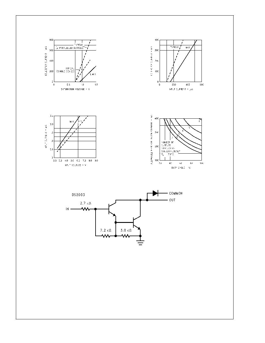
The DS2003 is comprised of seven high voltage, high cur-
rent NPN Darlington transistor pairs. All units feature com-
mon emitter, open collector outputs. To maximize their effec-
tiveness, these units contain suppression diodes for
inductive loads and appropriate emitter base resistors for
leakage.
The DS2003 has a series base resistor to each Darlington
pair, thus allowing operation directly with TTL or CMOS
operating at supply voltages of 5.0V.
The DS2003 offers solutions to a great many interface
needs, including solenoids, relays, lamps, small motors, and
LEDs. Applications requiring sink currents beyond the capa-
bility of a single output may be accommodated by paralleling
the outputs.
Features
n
Seven high gain Darlington pairs
n
High output voltage (V
CE
= 50V)
n
High output current (I
C
= 350 mA)
n
TTL, PMOS, CMOS compatible
n
Suppression diodes for inductive loads
n
Extended temperature range
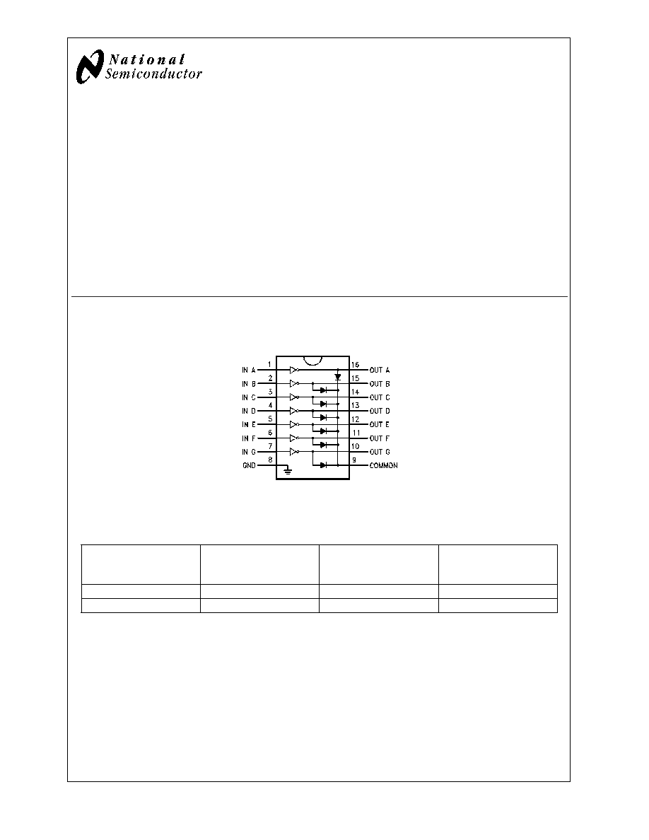
Connection Diagram
16-Lead DIP
00964701
Top View
Order Numbers
Operating
Temperature
Range
N Package
Number
N16E
SOIC Package
Number
M16A
TSSOP Package
Number
MT16
-40�C to +125�C
DS2003TN
DS2003TM
DS2003TMT
-40�C to +85�C
DS2003CN
DS2003CM
-
October 2002
DS2003
High
Current/V
oltage
Darlington
Drivers
� 2002 National Semiconductor Corporation
DS009647
www.national.com
Absolute Maximum Ratings
(Note 1)
If Military/Aerospace specified devices are required,
please contact the National Semiconductor Sales Office/
Distributors for availability and specifications.
Storage Temperature Range
-65�C to +150�C
Operating Temperature Range, T
A
DS2003T
-40�C to +125�C
DS2003C
-40�C to +85�C
Junction Temperature Range, T
J
-40�C to +150�C
Lead Temperature
Soldering, 10 seconds
265�C
ESD Ratings
Human Body Model
+/-2000V
Machine Model
+/- 200V
Package Thermal Dissipation Ratings
MT16 Package
J-A
130�C/W
N16E Package
J-A
88�C/W
M16A Package
J-A
115�C/W
Input Voltage
-0.3V to 30V
Output Voltage
55V
Emitter-Base Voltage
6.0V
Continuous Collector Current
500 mA
Continuous Base Current
25 mA
Electrical Characteristics
T
A
= 25�C, unless otherwise specified (Note 2)
Symbol
Parameter
Conditions
Min
Typ
Max
Units
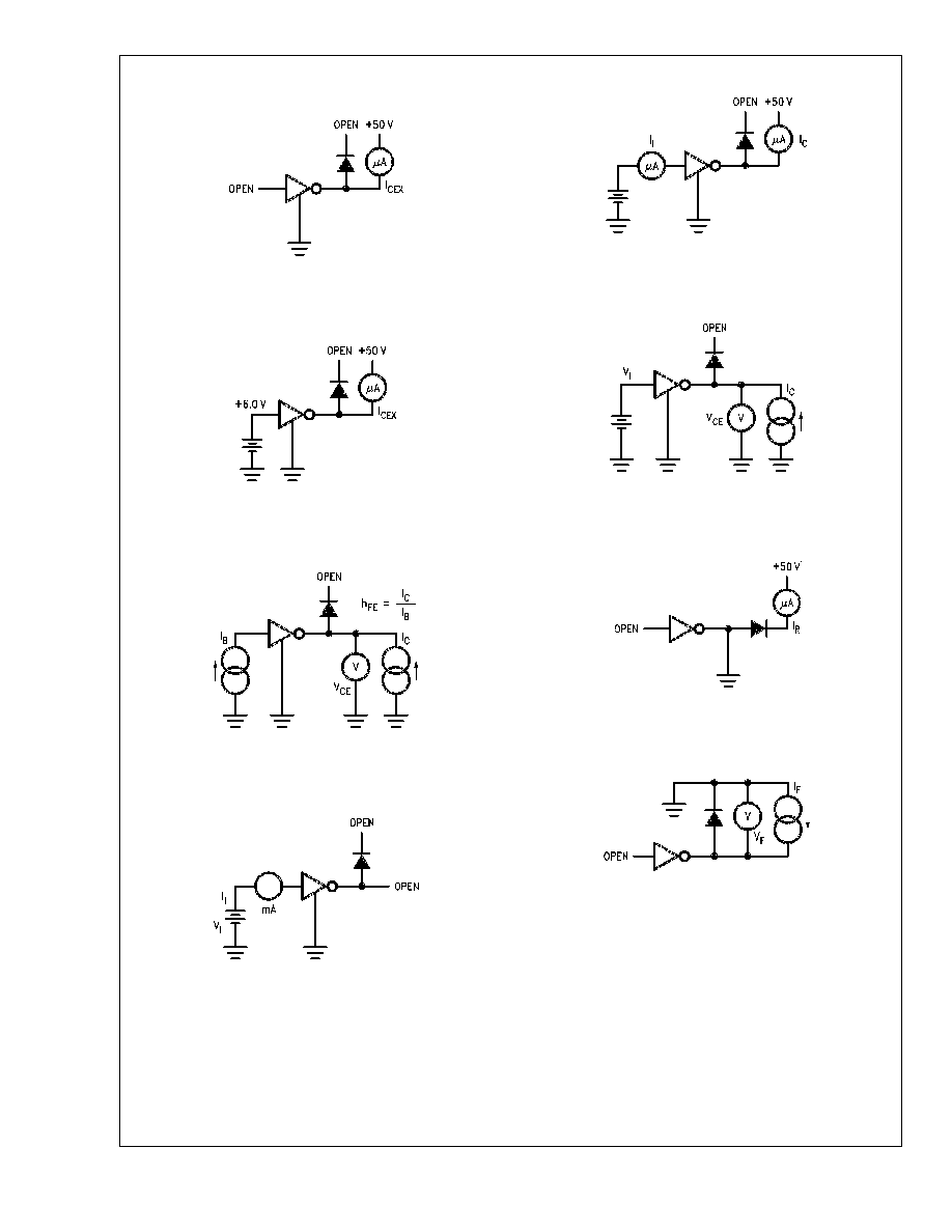
I
CEX
Output Leakage
Current
T
A
= 25�C, V
CE
= 50V (Figure 1)
20
T
A
= 85�C, V
CE
= 50V (Figure 1)
100
�A
T
A
= 125�C, V
CE
= 50V (Figure 1) for DS2003T
150
V
CE(Sat)
Collector-Emitter
Saturation Voltage
I
C
= 350mA, I
B
= 500�A (Figure 3) (Note 3)
1.25
1.6
V
I
C
= 200mA, I
B
= 350�A (Figure 3)
1.1
1.3
I
C
= 100mA, I
B
= 250�A (Figure 3)
0.9
1.1
I
I(ON)
Input Current
V
I
= 3.85V (Figure 4)
0.93
1.35
mA
I
I(OFF)
Input Current
(Note 4)
I
C
= 500�A (Figure 5)
50
100
�A
T
A
= +25C
10
25
�A
T
A
= +85C
25
50
�A
T
A
= +125C for DS2003T
50
100
�A
V
I(ON)
Input Voltage
(Note 5)
V
CE
= 2.0V, I
C
= 200mA (Figure 6 )
2.4
V
V
CE
= 2.0V, I
C
= 250mA (Figure 6 )
2.7
V
CE
= 2.0V, I
C
= 300mA (Figure 6 )
3.0
C
I
Input Capacitance
15
30
pF
t
PLH
Turn-On Delay
0.5 V
I
to 0.5 V
O
1.0
�s
t
PHL
Turn-Off Delay
0.5 V
I
to 0.5 V
O
1.0
�s
I
R
Clamp Diode
Leakage Current
V
R
= 50V (Figure 7)
T
A
= 25�C
5
10
�A
T
A
= 85�C
10
50
�A
T
A
= 125�C for DS2003T
20
100
�A
V
F
Clamp Diode
Forward Voltage
I
F
= 350mA (Figure 8 )
1.7
2.0
V
Note 1: "Absolute Maximum Ratings" are those values beyond which the safety of the device cannot be guaranteed. They are not meant to imply that the devices
should be operated at these limits. The tables of "Electrical Characteristics" provide conditions for actual device operation.
Note 2: All limits apply to the complete Darlington series except as specified for a single device type.
Note 3: Under normal operating conditions these units will sustain 350 mA per output with V
CE (Sat)
= 1.6V at 70�C with a pulse width of 20 ms and a duty cycle
of 30%.
Note 4: The I
I(OFF)
current limit guaranteed against partial turn-on of the output.
Note 5: The V
I(ON)
voltage limit guarantees a minimum output sink current per the specified test conditions.
DS2003
www.national.com
2
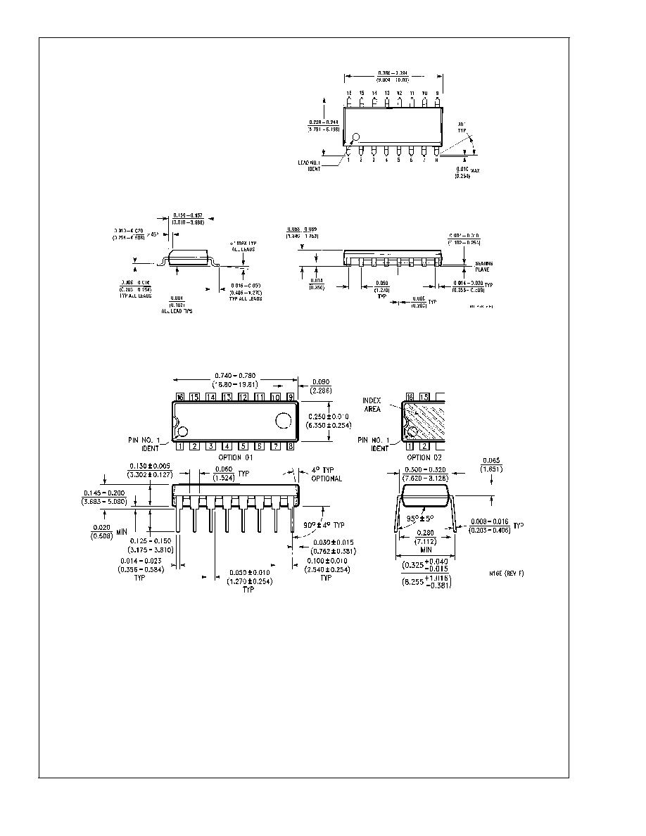
Physical Dimensions
inches (millimeters) unless otherwise noted
SOIC Package (M)
Order Number DS2003CM, DS2003TM
NS Package Number M16A
Molded Dual-In-Line Package (N)
Order Number DS2003CN, DS2003TN
NS Package Number N16E
DS2003
www.national.com
5