DS92UT16TUF
UTOPIA-LVDS Bridge for 1.6 Gbps Bi-directional Data
Transfers
1.0 General Description
The DS92UT16 is a flexible UTOPIA to LVDS Bridge device.
The LVDS Bridge transparently transports the UTOPIA bus
over a high speed LVDS serial link. The device includes
many reliability features such as an optional 1:1 protection
and built in bit error rate checking.
The parallel interface is user programmable for maximum
flexibility. The user can choose between UTOPIA Level Level
2 ATM layer (master) of PHY layer (slave). The UTOPIA-
LVDS Bridge supports a special MPHY (multi-PHY layer)
operation mode. The MPHY operation supports up to 248
standard UTOPIA Level 2 PHY ports without adding external
circuitry.
The serial interface uses LVDS Serializer and Deserializer
technology. The 16:1 bit serialization allows conveying the
full-duplex parallel bus over two differential transmission
pairs. This enables low cost backplanes and cables. Cable
transmission length can be as long 16 meters.
The serial link carries Flow control information (back pres-
sure) in both directions. The Bridge device applies back
pressure on a per queue basis over the 31 internal FIFO
queues. In addition, the serial link includes an OAM (Opera-
tions and Maintenance) channel that does not detract from
link performance.
There are many applications where the UTOPIA-LVDS
Bridge simplifies designs. Box-to-box connections can use
DS29UT16 devices across cables. Access multiplexor appli-
cations can use the devices across a PCB backplane for
point-to-point and lightly loaded multidrop configurations.
2.0 Features
n
832 Mbps LVDS 16-bit serializer and deserializer
interface
-- Suitable for cable, printed circuit board, and
backplane transmission paths
-- 10m cable at max LVDS data rate and greater than
16m at min LVDS data rate
-- Embedded clock with random data lock capability for
clock recovery
-- PRBS (x
31
+ x
28
+ 1) based LVDS link BER test
facility
-- Two independent LVDS receiver serial ports for
optional 1:1 protection
-- Main and redundant LVDS transmit ports
-- Loop timing capability enables LVDS recovered clock
to internally drive LVDS transmit clock
-- Internal buffers allow maximum LVDS serial bit rate
independent of UTOPIA clock rate
n
Programmable UTOPIA interface
-- UTOPIA Level 2 up to 52 MHz
-- ATM layer or PHY layer interface
-- ATM layer interface can support up to 248 standard
Level 2 PHY ports with no additional external
circuitry. Configured as 31 MPHY's, each with up to 8
sub-ports
-- Supports extended cell size up to 64 bytes
-- Supports 16- or 8-bit data buses with parity
n
Embedded bidirectional, non-blocking flow control over
serial link for per MPHY back pressure
n
No external memories required
n
Embedded OAM channel over serial link
-- Remote Alarm/Status Indications
-- Link Trace Label
-- Embedded Control Channel with flow control for
software communication
-- BIP16 based error performance monitoring
-- In protected systems, the standby link OAM channel
is available for embedded communications and
performance/alarm monitoring
n
Multiple loop-back options
n
Standard microprocessor interface (Intel and Motorola
compatible)
n
IEEE 1149.1 JTAG port
n
Temperature range: -40°C to +85°C
n
CMOS technology for low power
n
LVDS transceiver section uses 3.3V power supply.
Digital UTOPIA section uses 2.5V power supply. All I/O
are 3.3V tolerant.
n
196 LBGA package, 15x15x1.37 mm, 1.0 mm ball pitch
3.0 Ordering Information
Order Number
Package Information
Package Number
DS92UT16TUF
196 LBGA package, 15x15x1.37 mm, 1.0 mm ball pitch
NUJB0196
February 2004
DS92UT16TUF
UT
OPIA-L
VDS
Bridge
for
1.6
Gbps
Bi-directional
Data
T
ransfers
© 2004 National Semiconductor Corporation
DS200316
www.national.com
5.0 Application Overview
(Continued)
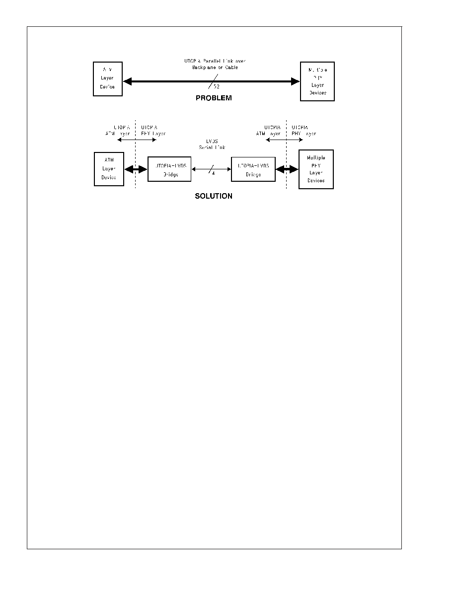
The UTOPIA interface [1. See Section 21.0 References] is
an established standard for connecting Physical Layer de-
vices to ATM Layer devices. However, when the ATM Layer
device and the Physical Layer device(s) are on separate
cards within a piece of equipment, or even on separate
equipment, then the parallel nature of this standard becomes
a limiting factor. See Figure 2.
The solution is to use the DS92UT16, which is a transparent
bridge that extends the UTOPIA bus over a serial LVDS
interface, and is suitable for backplanes and cables. Full
bidirectional flow control is incorporated, allowing back-
pressure to be applied to the source of the ATM cells. The 31
PHY ports available with standard UTOPIA Level 2 may be
extended to 248 ports without additional external circuitry.
The DS92UT16 achieves this by providing as many as 8
ENB and CLAV signals in both receive and transmit direc-
tions when acting as the ATM Layer device. This allows
addressing 248 PHYs that are configured as up to 31 ports
that each have as many as 8 sub-ports.
To aid equipment management and maintenance, the
DS92UT16 passes an embedded `Operations, Administra-
tion and Maintenance' (OAM) channel over the serial link. In
addition, the device provides a number of loopback options
that are both traffic affecting (line loopbacks) and non-traffic
affecting (cell loopbacks), which simplify testing and diag-
nostic activities.
The DS92UT16 has a modified Bus LVDS serial output for
driving cables in point-to-point applications. The cable length
depends on the quality of the cable and the data rate.
Increasing the cable quality, or lowering the LVDS data rate,
increases the maximum possible cable length the device will
drive.
When
examining
the
trade-offs
that
determine
the
DS92UT16 maximum cable drive capability, it is important to
understand that the LVDS data rate on the cable is 18 times
(16 bits plus 2 embedded clock bits) the LVDS_TxClk rate.
For example, a 35 MHz LVDS_TxClk will produce a
630 Mbps data rate, and a 52 MHz clock will produce a
936 Mbps data rate. When using twinaxial grade differential
cable, the cable length can be as long as 16m for the
35 MHz clock and approximately 10m for the 52 MHz clock.
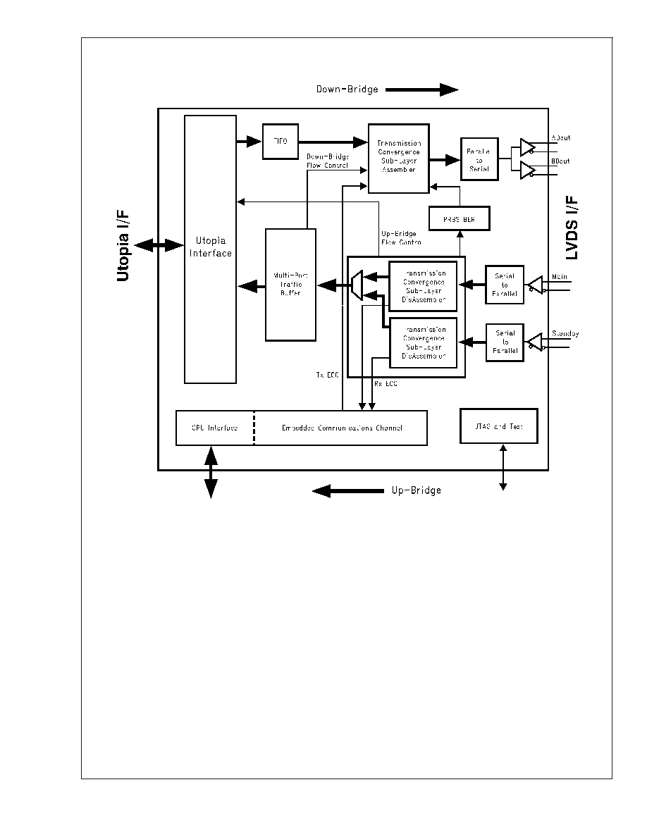
6.0 Functional Description
6.1 UTOPIA INTERFACE
The DS92UT16 has an industry standard UTOPIA interface
[1.] supporting Level 2 and Extended Level 2 operation.
Depending on its position in the bridge link, it may operate as
either the ATM layer or the physical layer in the UTOPIA
protocol.
In Level 2 mode, this interface can be either a 16-bit or an
8-bit wide data path, with both octet and cell level handshak-
ing and operating at a frequency as high as 52 MHz, facili-
tating 622 Mbps (STM4/OC12) line rates.
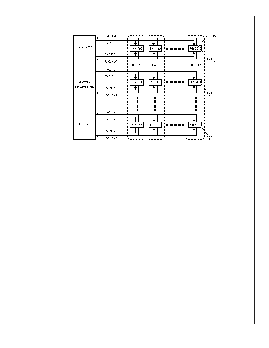
In UTOPIA Level 2 mode, the device supports Multi-PHY
(MPHY) operation, whereby up to 31 PHY ports may be
connected to an ATM device. The presence of cells and
availability of buffer space is indicated using the CLAV sig-
nals.
UTOPIA Level 2 defines 1 ENB and 1 CLAV signal in each
direction. The DS92UT16 has extended this to 8 ENB and 8
CLAV signals, which enables up to 248 PHY ports to be
connected to an ATM device without additional external cir-
cuitry as shown in Figure 3.
20031602
FIGURE 2. Application Example
DS92UT16TUF
www.national.com
3
6.0 Functional Description
(Continued)
For the purposes of queueing, the 248 PHY ports are con-
figured as sub-ports of the standard 31 ports so each port/
queue has 8 sub-ports as discussed in Section 6.2.2 Up-
Bridge Multi-Port Traffic Buffer. Each MPHY address
corresponds to a port.
The 5 bit MPHY can address up to 31 PHY ports. At least 3
additional bits are required to give the total of 8 bits neces-
sary for addressing 248 PHY ports. These additional ad-
dress bits can be provided by the user in any of the User
Prepend, Cell Header or UDF1/2 bytes of the cell as shown
in Figure 6. The DS92UT16 is configured to extract/insert the
extra address bits from/to any of these bytes.
PHY polling may be carried out as follows:
·
Standard UTOPIA Level 2 with 1 CLAV signal.
-- One CLAV polling 31 PHY ports.
·
DS92UT16 Extended UTOPIA Level 2 with up to 8 CLAV
signals.
-- Each CLAV can poll 31 PHY ports giving a total of 248
PHY ports.
Multiple UTOPIA-LVDS bridge devices can be used in par-
allel to share up to 31 PHY ports among PHYs that are on
separate line cards Figure 5. Each of these ports may have
up to 8 sub-ports. There are constraints on the number of
port addresses used per bridge in such a configuration. See
Section 9.2 MULTIPLE BRIDGE MTB CONFIGURATION
20031627
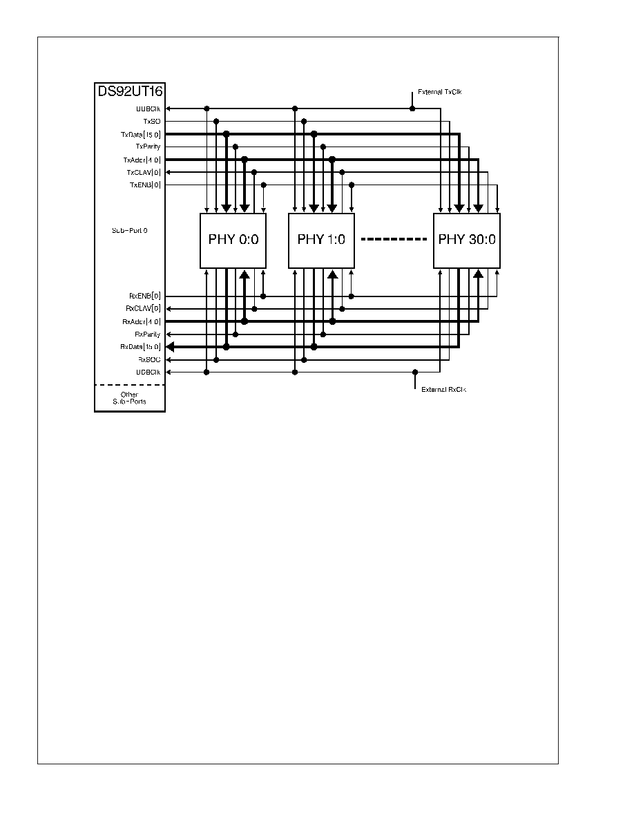
FIGURE 4. Detailed Connection of One Sub-Port for Extended UTOPIA Level 2
DS92UT16TUF
www.national.com
5