
FPD87392BXB
+3.3V TFT-LCD Timing Controller with Dual LVDS
Inputs/Dual RSDS
TM
Outputs for TFT-LCD Monitor and
Notebook (SXGA/SXGA+/UXGA)
General Description
The FPD87392BXB Panel Timing Controller is an integrated
FPD-Link + RSDS
TM
+ TFT-LCD Timing Controller. The logic
architecture is implemented using standard and default tim-
ing controller functionality based on an Embedded Gate
Array. The device is reconfigurable to the needs of a specific
application by providing user-defined specifications or cus-
tomer supplied VHDL/Verilog code.
The FPD87392BXB is a timing controller that combines an
LVDS dual pixel input interface with National's Reduced
Swing Differential Signaling (RSDS
TM
) output column driver
interface for SXGA, SXGA+ and UXGA resolutions. It re-
sides on the TFT-LCD panel and provides the data buffering
and control signal generation. The RSDS
TM
data path to the
column driver contributes toward lowering radiated EMI and
reduced system dynamic power consumption. The RSDS
TM
dual 12 pair differential bus conveys up to 24-bit color data
for SXGA/SXGA+/UXGA panels when using VESA 60Hz
standard timing.
Features
n
Input frequency range from 25 MHz to 85 MHz
n
Support display resolutions SXGA (1280x1024), SXGA+
(1400x1050) and UXGA (1600x1200)
n
Embedded gate array for custom panel timing
n
RSDS
TM
(Reduced Swing Differential Signaling) Column
Driver bus for low power and reduced EMI
n
Drives RSDS
TM
column driver up to 170 Mb/s with an 85
MHz clock
n
6 or 8 bit LVDS dual pixel input interface (FPD-Link)
n
Virtual 8-bit color depth in FRC mode
n
Flexible RSDS
TM
data output mapping for Bottom or Top
mount
n
Supports 1 and 2 line inversion mode for RVS output
n
Supports Graphics Controllers with spread spectrum
interface for lower EMI
n
Free Run Mode Function
n
Fail-safe function in DE mode (Bonding Option)
n
Supports DE mode and SYNC only mode (Bonding
Option)
n
Power-On-Reset Support
n
CMOS circuitry operates from a 3.0V to 3.6V supply
n
128 TQFP package with body size 14mm x 14mm x
1.0mm, 0.4mm Pitch
July 2004
FPD87392BXB
+3.3V
TFT
-LCD
T
iming
Controller
with
Dual
L
VDS
Inputs/Dual
RSDS
TM
Outputs
for
TFT
-LCD
Monitor
and
Notebook
(SXGA/SXGA+/UXGA)
© 2004 National Semiconductor Corporation
DS201043
www.national.com

Block Diagram
Functional Description
DUAL FPD-LINK RECEIVERS
The LVDS based FPD-Link Receivers inputs video data and
control timing through 8 pairs of LVDS channels plus 2 pairs
of LVDS clocks to provide 24-bit color or use only 6 pairs of
LVDS channels plus 2 LVDS clocks to provide 18-bit color.
The video data is converted to a parallel data stream and
routed to the 8-6 bit translator.
SPREAD SPECTRUM SUPPORT
The FPD-Link receiver supports graphics controllers with
Spread Spectrum interfaces for reducing EMI. The Spread
Spectrum methods supported are Center and Down Spread.
A maximum of 2% total is supported at a frequency modu-
lation of 100kHz maximum.
8-6 BIT TRANSLATOR
8-bit data is reduced to a 6-bit data path via a time multi-
plexed dithering technique or simple truncation of the LSBs.
This function is enabled via the input control pins.
DATAPATH BLOCK AND RSDS TRANSMITTER
6(8)-bit video data (RGB) is input to the Datapath Block
supports up to an 85 MHz dual pixel rate. The data is
delayed to align the Column Driver Start Pulse (STH) with
the Column Driver data. The dual data bus (RSR[3:0]P/N,
RSG[3:0]P/N, RSB[3:0]P/N) outputs at a 170 MHz rate on 24
differential output channels. The clock is output on the
(Front, Back) RSCKP/N differential pairs. The RSDS Column
Drivers latch data on both positive and negative edges of the
clock. The swap function provides flexible RSDS data output
mappings for either Top or Bottom mount. The RSDS output
setup/hold
timings
are
also
adjustable
through
the
RSKEW[2:0] input pins.
TIMING CONTROL FUNCTION
The Timing Control function generates control to Column
Drivers, Row Drivers, and power supply. The GPOs (General
Purpose Outputs) provide for CD latch pulse, REV, and Row
Driver control generation. The General Purpose Outputs
allow the user to generate control anywhere within the frame
data. Standard Row Driver interface or Custom Row Driver
interfaces can be implemented with the GPOs (General
Purpose Outputs).
RSDS OUTPUT VOLTAGE CONTROL
The RSDS output voltage swing is controlled through an
external load resistor connected to the RPI pin. The RSDS
output signal levels can be adjusted to suit the particular
application. This is dependent on overall LCD module design
characteristics such as trace impedance, termination, etc.
The RSDS output voltage is inversely related to the RPI
value. Lower RPI values will increase the RSDS output
voltage swing and consequently overall power consumption
will also increase.
20104328
FIGURE 2. Block Diagram
FPD87392BXB
www.national.com
3
Absolute Maximum Ratings
(Note 1)
If Military/Aerospace specified devices are required,
please contact the National Semiconductor Sales Office/
Distributors for availability and specifications.
Supply Voltage (V
DD
)
-0.3V to +4.0V
DC TTL Input Voltage (V
IN
)
-0.3V to (V
DD
+ 0.3V)
DC LVDS Input Voltage (V
IN
)
-0.3V to (V
DD
+ 0.3V)
DC Output Voltage (V
OUT
)
-0.3V to (V
DD
+ 0.3V)
Junction Temperature
+150∞C
Storage Temperature Range
(T
STG
)
-65∞C to +150∞C
Lead Temperature (T
L
)
(Soldering 10 sec.)
260∞C
ESD Rating:
(C
ZAP
= 120 pF,
MM = 200V,
R
ZAP
= 1500W)
HBM = 2000V
Operating Conditions
Min
Max
Units
Supply Voltage (V
DD
)
3.0
3.6
V
Operating Temp. Range (T
A
)
0
70
∞C
Supply Noise Voltage
100
mV
PP
DC Electrical Characteristics
T
A
= 0∞C to 70∞C, V
DD
= 3.0V to 3.6V, I
PI
= 100 µA (Unless otherwise specified)
TTL DC Electrical Characteristics
Symbol
Parameter
Conditions
Min
Typ
Max
Units
V
DD
Core Supply Voltage
3.0
3.3
3.6
V
V
IH
Minimum Input High Voltage
2.0
V
V
IL
Maximum Input Low Voltage
0.8
V
V
OH
Output High Voltage
I
OH
= -8mA
V
DD
-0.6
V
V
OL
Output Low Voltage
I
OL
= 8 mA
0.4
V
I
IN
Input Current
V
IN
= V
DD
, GND
±
10
µA
I
PU
Pull-Up Current
V
DD
= 3.3V, V
IN
= V
DD
-50
µA
I
PD
Pull-Down Current
V
DD
= 3.3V, V
IN
= GND
+50
µA
I
DD
Average Supply Current
C
L(TTL)
= 15 pF,
R
L(RSDS)
= 100
and
C
L(RSDS)
= 5 pF
(jig & test fixture capacitance),
I
PI
= 100 µA
(Typically PI pin connected to
13 k
to ground), See Figure 3
for input conditions
170
(CLK = 65
MHz,
V
DD
= 3.3V)
250
(CLK = 85
MHz,
V
DD
= 3.6V)
mA
Note 1: "Absolute Maximum Ratings" are those values beyond which the safety of the device cannot be guaranteed. They are not meant to imply that the devices
should be operated at these limits. The table of "Electrical Characteristics" specifies conditions of device operation.
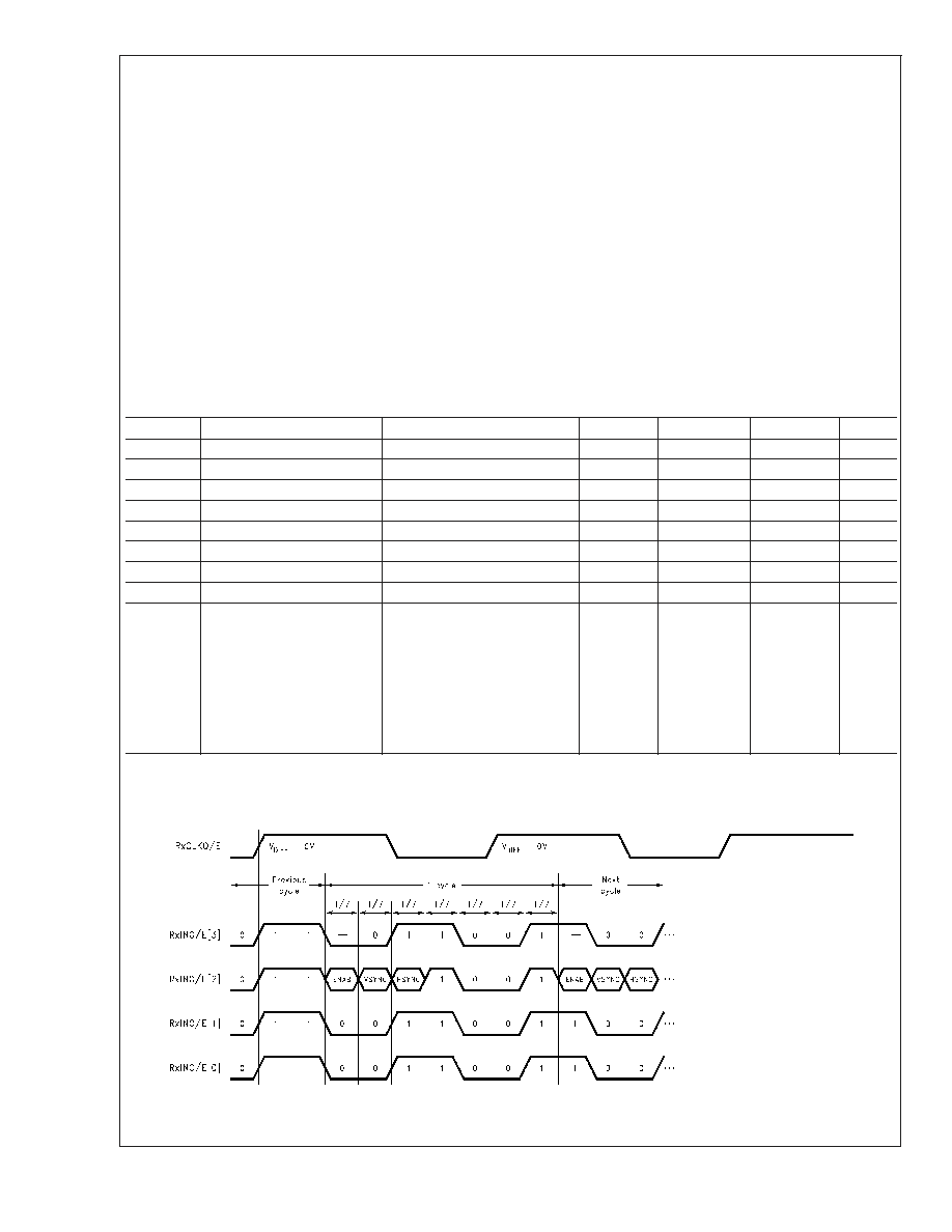
20104302
FIGURE 3. FPD-Link Receiver Input Pattern Used to Measure I
DD
FPD87392BXB
www.national.com
4

DC Electrical Characteristics
T
A
= 0∞C to 70∞C, V
DD
= 3.0V to 3.6V, I
PI
= 100 µA (Unless otherwise specified) (Continued)
FPD-Link (LVDS) Receiver Input Characteristics
Symbol
Parameter
Conditions
Min
Typ
Max
Units
LVDS RECEIVER DC SPECIFICATIONS
Note: LVDS Receiver DC parameters are measured under static and steady state conditions which may not reflect the
actual performance in the end application.
V
THLVDS
Differential Input High Threshold
Voltage
V
CM
= 1.2V
+100
mV
V
TLLVDS
Differential Input Low Threshold
Voltage
-100
mV
I
IN
Input Current
V
IN
= 2.05V, V
DD
=
3.6V
±
10
µA
V
IN
= 0.55V, V
DD
=
3.6V
±
10
µA
V
IN
Input Voltage Range (Single-ended)
V
DD
= 3.0 ≠ 3.6V
0.55
2.00
V
|V
ID
|
Differential Input Voltage
0.100
0.600
V
V
CM
Common Mode Voltage Offset
V
DD
= 3.0 ≠ 3.6V
0.55 + |V
ID
|/2
2.05 - |V
ID
|/2
V
20104303
FIGURE 4. FPD-Link Receiver V
ID
and V
CM
Definitions
FPD87392BXB
www.national.com
5
