LM1253A
Monolithic Triple 180 MHz I
2
C CRT Pre-amp With
Integrated Analog On Screen Display (OSD) Generator
General Description
The LM1253A pre-amp is an integrated high voltage triple
CRT pre-amp and Analog On Screen Display (OSD) genera-
tor. The IC is I
2
C controlled, and allows control of all the pa-
rameters necessary to setup and adjust the brightness and
contrast in the CRT display. In addition, it provides a pro-
grammable period vertical blanking pulse which is used to
blank the G1.
The LM1253A pre-amp is designed to work in cooperation
with the LM2453 driver, and provides a multiplexed video
signal (VideoPlex) interface to enable the DC clamp levels at
the cathode to be varied in order to set up the CRT bias and
to allow individual adjustment for brightness.
The Analog OSD has a selectable palette allowing a wide se-
lection of colors. The preset level of the OSD can be con-
trolled by I
2
C to suit different CRT displays. The OSD signal
is internally mixed with the video signal, before the gain sec-
tion, and thus gives excellent white tracking of the OSD with
the white color point setting of the video.
The Brightness settings are also mixed into the video signal
before the gain matching controls and consequently give ex-
cellent white color point tracking with variations in the Bright-
ness control. An active horizontal blanking signal is added to
the video at the output, giving excellent smear performance,
and preventing video content dependent DC bias offsets as
a result of high frequency over shoot.
The OSD horizontal sync and blanking signal is derived from
a positive going flyback pulse. The digital section provides
easy interfacing of this signal with the deflection circuits.
The vertical blanking signal is taken from the vertical sync
signal, and the blanking duration is programmable. This sys-
tem is highly integrated and requires a minimal number of
external components.
Black level clamping of the signal is carried out directly on
the AC coupled input signal into the high impedance pream-
plifier input, thus eliminating the need for additional black
level clamp capacitors.
The outputs are referenced to a DC level produced by the
LM1253A Pre-amp, and so are guaranteed to provide stable
DC operating levels within the system without the need for
additional external feedback components.
The IC is packaged in an industry standard wide body 28-
lead DIL molded plastic package.
Features
n
190 two-color ROM based Character Fonts
n
64 four-color ROM based Character Fonts
n
Supports a programmable page size with up to 512
characters and line definition codes
n
Support for 2 Display Windows (size of each window is
configurable)
n
Programmable start position for each Display Window
n
Programmable Resolutions: from 512 to 960 pixels per
line in 64 pixel increments
n
Programmable Character Height, with automatic height
control with mode change
n
Programmable Row Spacing between each display
character row
n
Maximum Pixel clock of 92.2 MHz
n
I
2
C compatible interface to controlling micro-controller
n
Button boxes
n
180 MHz preamplifier with full video signal parametric
control
n
VideoPlex
TM
interface to the LM2453 driver
n
OSD mixing with 64 out of 512 color mask
programmable selection
Intended Applications
n
1280 x 1024 Displays up to 75 Hz requiring OSD
capability
May 2000
LM1253A
Monolithic
T
riple
180
MHz
I
2
C
CRT
Pre-amp
W
ith
Integrated
Analog
On
Screen
Display
(OSD)
Generator
� 2000 National Semiconductor Corporation
DS101265
www.national.com

Table of Contents
Block and Connection Diagrams
3
Absolute Maximum Ratings
5
Operating Ratings
5
Electrical Characteristics
5
Test Circuit
7
Test Settings
8
Pin Descriptions
8
Input/Output Schematics
13
National VideoPlex Video System
15
ESD and Arc-Over Protection
16
Pre-Amp Functional Description
17
Horizontal Phase Locked Loop
19
Fault Operation
19
Power Save Mode
19
Schematics
20
PCB Layout
22
OSD Generator Operation
23
Micro-Controller Interface
27
LM1253A Address Map
29
Pre-Amp Interface Registers
30
Two-Color Attribute Table
31
Four-Color Attribute Table
31
Display Page RAM
32
Controller Register Definitions
40
Character Font
51
List of Tables
Table 1 Control Test Settings
7
Table 2 Registers Controlling the Output
Video and Clamp Signal
18
Table 3 Character ROM Address Map
29
Table 4 Display Page RAM Address Map
29
Table 5 OSD Interface Registers
30
Table 6 Pre-Amp Interface Registers
31
Table 7 Two-Color Attribute Registers
31
Table 8 Four-Color Attribute Registers
31
Table 9 Example 1 I
2
C Transmission
35
Table 10 Example 2 I
2
C Transmissions
36
Table 11 Example 3 I
2
C Transmissions
39
Table 12 PLL Setting (Register 843Eh)
46
Table 13 Attribute Tables to I
2
C Address
48
LM1253A
www.national.com
2

Block and Connection Diagrams
DS101265-1
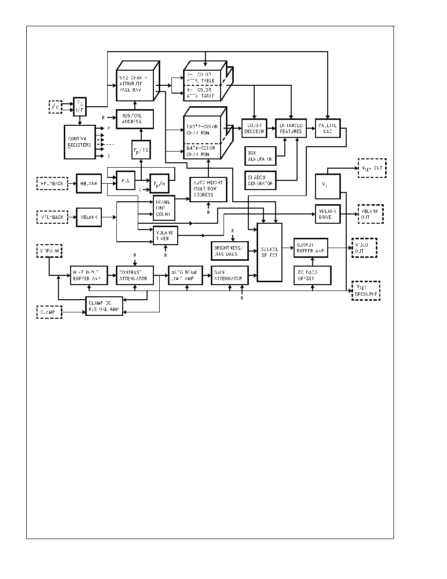
FIGURE 1. Block Diagram
LM1253A
www.national.com
3

Block and Connection Diagrams
(Continued)
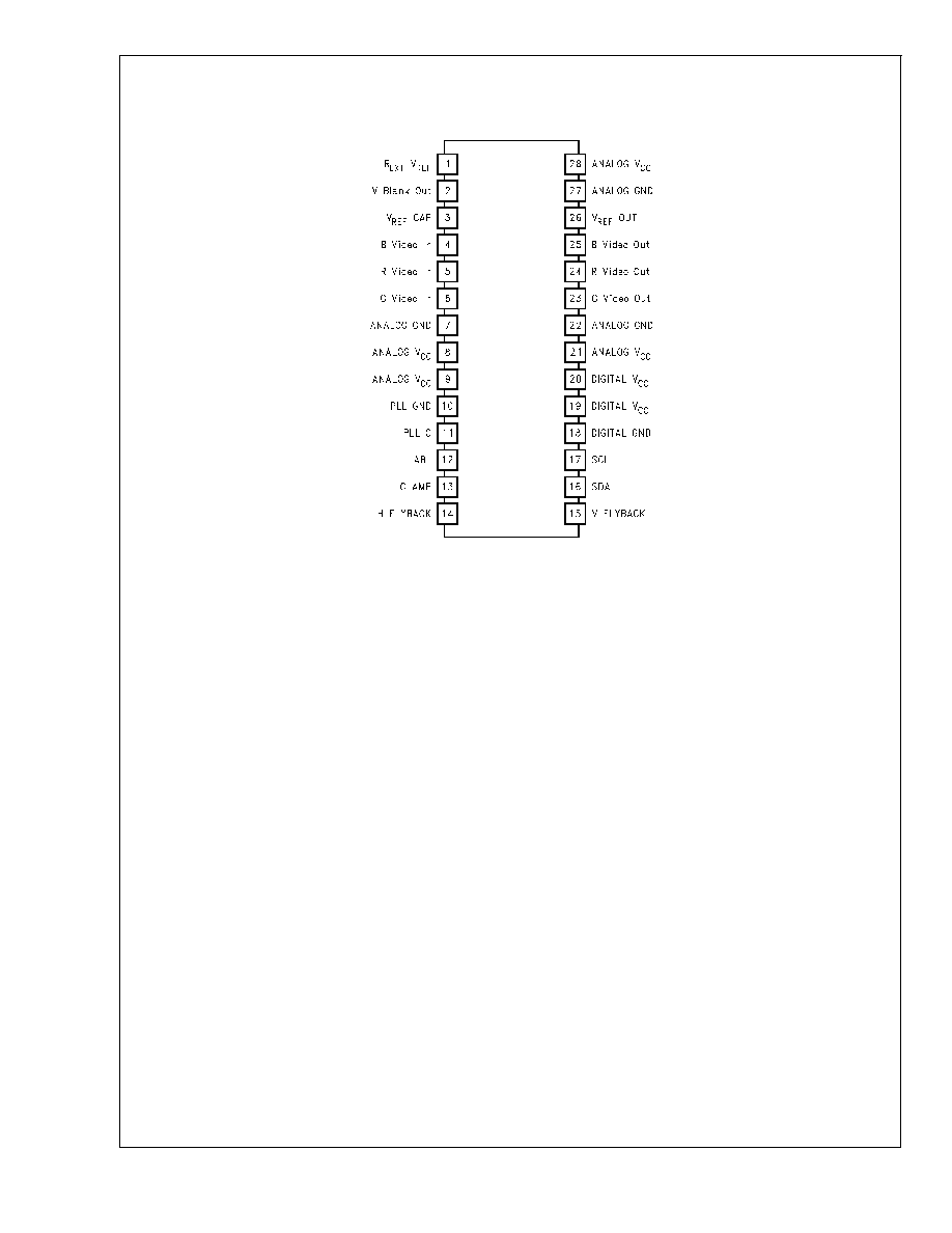
28-Lead (0.600'' wide) Molded Dual-In-Line Package
DS101265-2
Order Number LM1253AN
See NS Package Number N28B
FIGURE 2. Connection Diagram
LM1253A
www.national.com
4

Absolute Maximum Ratings
(Notes 1, 3)
If Military/Aerospace specified devices are required,
please contact the National Semiconductor Sales Office/
Distributors for availability and specifications.
Supply Voltage, (V
CC
)
6V
Input Voltage, (V
IN
)
6V
Storage Temperature Range, (T
STG
)
-65�C to +150�C
T
JMAX
150�C
Lead Temperature (Soldering,
<
10 sec.)
300�C
ESD Tolerance, Human Body Model
3 kV
Machine Model
300V
Operating Ranges
(Note 2)
Temperature Range
0�C to +70�C
V
CC
+4.75V to +5.25V
Active Video Signal Electrical Characteristics
(See
Figure 3 for Test Circuit, and Table 1 for Control Test Settings Chart)
Unless otherwise noted: V
CC
= +5V, V
IN
= 0.7V, C
L
= 8 pF, Video Signal Output = 1 V
PP
, T
A
= 25�C, V
ABL
= V
CC
.
Symbol
Parameter
Conditions
LM1253A
Units
Min
Typ
Max
I
CC1MAX
Maximum Supply Current
Test Setting 1, No Output Load
245
mA
V
OUT BLK
Active Video Black Level Minimum
Output Voltage
Test Setting 1, No AC Input Signal
V
REF
V
DC
LE
Linearity Error
Test Setting 3, (Note 4), Triangular
Step Signal Input
1
%
V
OUT WHITE
Active Video White Level Max
Output Voltage
Test Setting 3, AC Input Signal
2.7
V
t
r
Rise Time
Test Setting 3, (Note 5), 10% to
90%, AC Input Signal
3.0
ns
t
f
Fall Time
Test Setting 3, (Note 5), 90% to
10%, AC Input Signal
3.0
ns
OS
R
Rising Edge Overshoot
Test Setting 3, (Note 5), AC Input
Signal
5
%
OS
F
Falling Edge Overshoot
Test Setting 3, (Note 5), AC Input
Signal
5
%
f(-3dB)
Video Amplifier Bandwidth
Measured in AC2DC002 Demo
Board. LM1253A set for 40 V
PP
swing at LM2453 output
180
MHz
A
CONTRAST
Contrast Max-Min Adjustment
Range
Test Setting 2, AC Input Signal
20
dB
A
GAIN
Gain Max-Min Adjustment Range
Test Setting 2, AC Input Signal
10
dB
A
MAX
Max Signal Voltage Gain
Test Setting 2, AC Input Signal
1.8
V/V
V
ABL TH
Auto Beam Limit Control Upper
Limit
Test Setting 3, (Note 6), AC Input
Signal
4.5
V
V
ABL RANGE
Auto Beam Limit Control Voltage
Range
Test Setting 3, (Note 6), AC Input
Signal
3
V
A
ABL
Auto Beam Limit Control Range
Test Setting 3, (Note 6), AC Input
Signal
-10
dB
I
ABL MAX
Auto Beam Limit Input Current
Sink Capability
Test Setting 3, (Note 6), AC Input
Signal
1
mA
C
IP
Input AC Coupling Capacitor
Test Setting 3
4.7
nF
V
REF
Typical V
REF
Output Voltage
1.55
1.65
1.75
V
XT
Channel to Channel Crosstalk
10 MHz
40
dB
LM1253A
www.national.com
5


