 | –≠–ª–µ–∫—Ç—Ä–æ–Ω–Ω—ã–π –∫–æ–º–ø–æ–Ω–µ–Ω—Ç: LM1830 | –°–∫–∞—á–∞—Ç—å:  PDF PDF  ZIP ZIP |
TL H 5700
LM1830
Fluid
Detector
February 1995
LM1830 Fluid Detector
General Description
The LM1830 is a monolithic bipolar integrated circuit de-
signed for use in fluid detection systems The circuit is ideal
for detecting the presence absence or level of water or
other polar liquids An AC signal is passed through two
probes within the fluid A detector determines the presence
or absence of the fluid by comparing the resistance of the
fluid between the probes with the resistance internal to the
integrated circuit An AC signal is used to overcome plating
problems incurred by using a DC source A pin is available
for connecting an external resistance in cases where the
fluid impedance is of a different magnitude than that of the
internal resistor
When the probe resistance increases
above the preset value the oscillator signal is coupled to
the base of the open-collector output transistor In a typical
application the output could be used to drive a LED loud
speaker or a low current relay
Features
Y
Low external parts count
Y
Wide supply operating range
Y
One side of probe input can be grounded
Y
AC coupling to probe to prevent plating
Y
Internally regulated supply
Y
AC or DC output
Applications
Y
Beverage dispensers
Y
Radiators
Y
Water softeners
Y
Washing machines
Y
Irrigation
Y
Reservoirs
Y
Sump pumps
Y
Boilers
Y
Aquaria
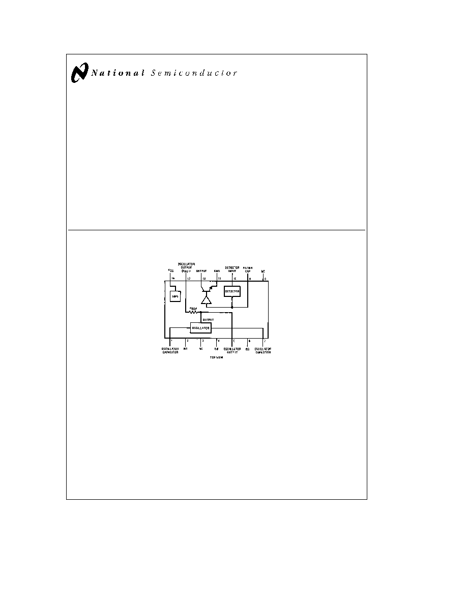
Logic and Connection Diagram
Dual-In-Line Package
TL H 5700 ≠ 1
Order Number LM1830N
See NS Package Number N14A
C1995 National Semiconductor Corporation
RRD-B30M115 Printed in U S A
Absolute Maximum Ratings
If Military Aerospace specified devices are required
please contact the National Semiconductor Sales
Office Distributors for availability and specifications
Supply Voltage
28V
Power Dissipation (Note 1)
1400 mW
Output Sink Current
20 mA
Operating Temperature Range
b
40 C to
a
85 C
Storage Temperature Range
b
40 C to
a
150 C
Lead Temp (Soldering 10 seconds)
260 C
Electrical Characteristics
(V
a
e
16V T
A
e
25 C unless otherwise specified)
Parameter
Conditions
Min
Typ
Max
Units
Supply Current
5 5
10
mA
Oscillator Output Voltage
Low
1 1
V
High
4 2
V
Internal Reference Resistor
8
13
25
kX
Detector Threshold Voltage
680
mV
Detector Threshold Resistance
5
10
15
kX
Output Saturation Voltage
I
O
e
10 mA
0 5
2 0
V
Output Leakage
V
PIN 12
e
16V
10
m
A
Oscillator Frequency
C1
e
0 00 1mF
4
7
12
kHz
Note 1
The maximum junction temperature rating of the LM1830N is 150 C For operation at elevated temperatures devices in the dual-in-line plastic package
must be derated based on a thermal resistance of 89 C W
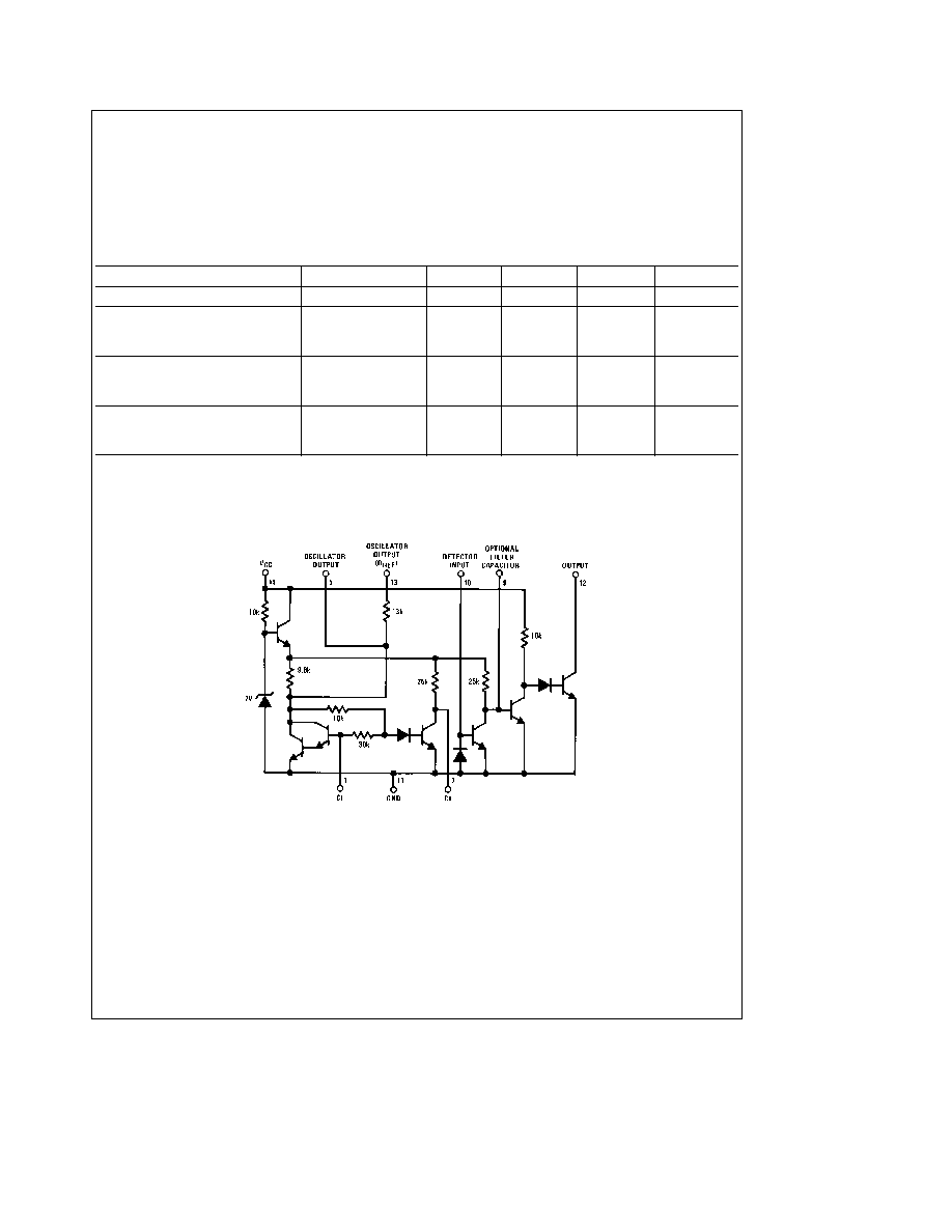
Schematic Diagram
TL H 5700 ≠ 2
2
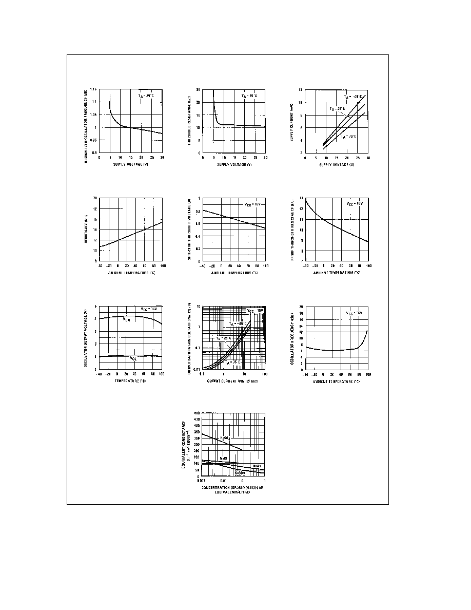
Typical Performance Characteristics
Normalized Oscillator Frequency
vs Supply Voltage
Threshold Resistance vs Supply
Voltage
Power Supply Current vs
Supply Voltage
Reference Resistor vs Ambient
Temperature
Detector Threshold Voltage
vs Temperature
Probe Threshold Resistance
vs Temperature
Oscillator V
OH
and V
OL
vs Ambient Temperature
Output Saturation Voltage vs
Output Current
Oscillator Frequency vs
Ambient Temperature
Equivalent Resistance vs
Concentration of Several
Solutions
TL H 5700 ≠ 3
3

Application Hints
The LM1830 requires only an external capacitor to com-
plete the oscillator circuit The frequency of oscillation is
inversely proportional to the external capacitor value Using
0 001mF capacitor the output frequency is approximately 6
kHz The output from the oscillator is available at pin 5 In
normal applications the output is taken from pin 13 so that
the internal 13k resistor can be used to compare with the
probe resistance Pin 13 is coupled to the probe by a block-
ing capacitor so that there is no net dc on the probe
Since the output amplitude from the oscillator is approxi-
mately 4 V
BE
the detector (which is an emitter base junc-
tion) will be turned ``ON'' when the probe resistance to
ground is equal to the internal 13 kX resistor An internal
diode across the detector emitter base junction provides
symmetrical limiting of the detector input signal so that the
probe is excited with
g
2 V
BE
from a 13 kX source In cases
where the 13 kX resistor is not compatible with the probe
resistance range an external resistor may be added by cou-
pling the probe to pin 5 through the external resistor as
shown in
Figure 2 The collector of the detecting transistor
is brought out to pin 9 enabling a filter capacitor to be con-
nected so that the output will switch ``ON'' or ``OFF'' de-
pending on the probe resistance If this capacitor is omitted
the output will be switched at approximately 50% duty cycle
when the probe resistance exceeds the reference resist-
ance This can be useful when an audio output is required
and the output transistor can be used to directly drive a loud
speaker In addition LED indicators do not require dc exci-
tation Therefore the cost of a capacitor for filtering can be
saved
In the case of inductive loads or incandescent lamp loads it
is recommended that a filter capacitor be employed
In a typical application where the device is employed for
sensing low water level in a tank a simple steel probe may
be inserted in the top of the tank with the tank grounded
Then when the water level drops below the tip of the probe
the resistance will rise between the probe and the tank and
the alarm will be operated This is illustrated in
Figure 3 In
situations where a non-conductive container is used the
probe may be designed in a number of ways In some cases
a simple phono plug can be employed Other probe designs
include conductive parallel strips on printed circuit boards
It is possible to calculate the resistance of any aqueous
solution of an electrolyte for different concentrations pro-
vided the dimensions of the electrodes and their spacing is
known
The resistance of a simple parallel plate probe is given by
R
e
1000
c p
d
A
X
where
A
e
area of plates (cm
2
)
d
e
separation of plates (cm)
c
e
concentration (gm mol equivalent litre)
p
e
equivalent conductance
(X
b
1
cm
2
equiv
b
1
)
(An equivalent is the number of moles of a substance that
gives one mole of positive charge and one mole of negative
charge For example one mole of NaCl gives Na
a
a
Cl
b
so
the equivalent is 1 One mole of CaCl
2
gives Ca
a a
a
2Cl
b
so the equivalent is 1 2 )
Usually the probe dimensions are not measured physically
but the ratio d A is determined by measuring the resistance
of a cell of known concentration c and equivalent conduct-
ance of 1 A graph of common solutions and their equivalent
conductances is shown for reference The data was derived
from D A Maclnnes ``The Principles of Electrochemistry ''
Reinhold Publishing Corp New York 1939
In automotive and other applications where the power
source is known to contain significant transient voltages the
internal regulator on the LM1830 allows protection to be
provided by the simple means of using a series resistor in
the power supply line as illustrated in
Figure 4 If the output
load is required to be returned directly to the power supply
because of the high current required it will be necessary to
provide protection for the output transistor if the voltages
are expected to exceed the data sheet limits
Although the LM1830 is designed primarily for use in sens-
ing conductive fluids it can be used with any variable resist-
ance device such as light dependent resistor or thermistor
or resistive position transducer
The following table lists some common fluids which may
and may not be detected by resistive probe techniques
Conductive Fluids
Non-Conductive Fluids
City water
Pure water
Sea water
Gasoline
Copper sulphate solution
Oil
Weak acid
Brake fluid
Weak base
Alcohol
Household ammonia
Ethylene glycol
Water and glycol mixture
Paraffin
Wet soil
Dry soil
Coffee
Whiskey
4
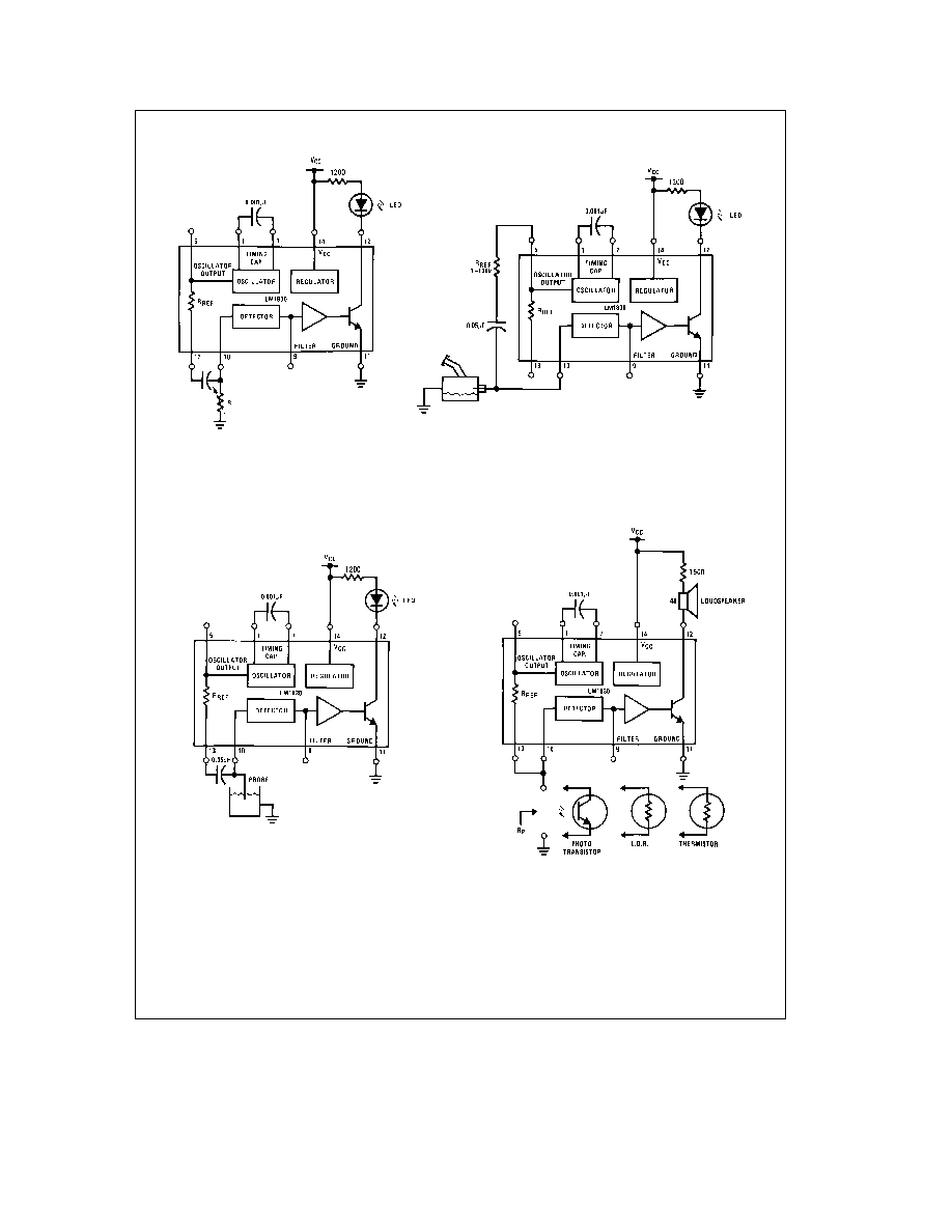
Typical Applications
V
CC
e
16V
FIGURE 1 Test Circuit
FIGURE 2 Application Using External
Reference Resistor
TL H 5700 ≠ 4
FIGURE 3 Basic Low Level Warning Device
with LED Indication
Output is activated when R
p
is approximately greater than
R
REF
FIGURE 4 Direct Coupled Applications
5