LM2792
Current Regulated Switched Capacitor LED Driver with
Analog Brightness Control
General Description
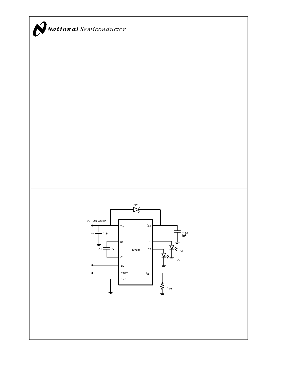
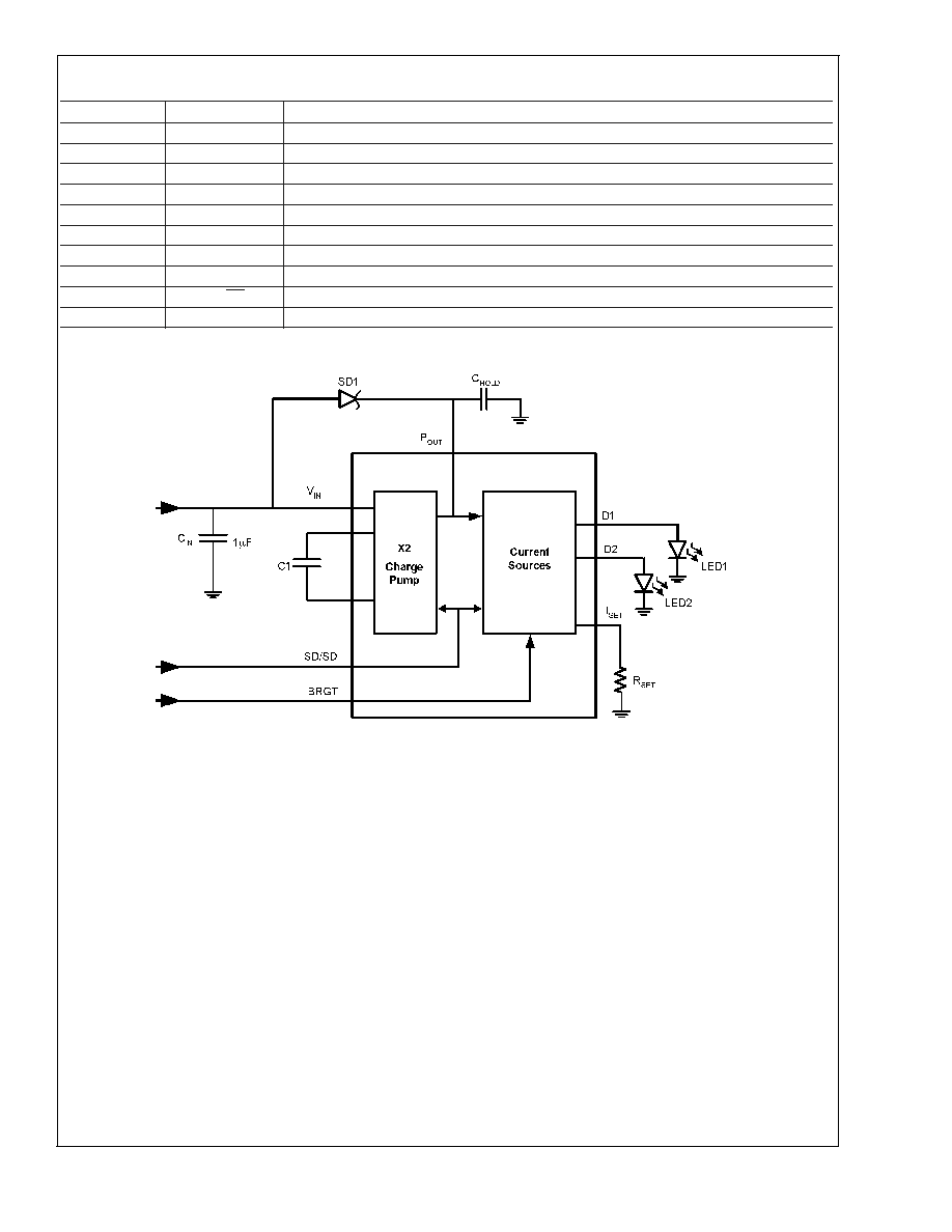
The LM2792 is a CMOS charge-pump voltage doubler and
regulator that provides two regulated current sources. They
are designed to drive two white (or blue) LEDs with matched
currents (within
±
0.3%) to produce balanced light sources
for display backlights. The LM2792 accepts an input voltage
range from 3.0V to 5.8V and maintain a constant current
determined by an external set resistor.
The LM2792 delivers up to 34mA of load current to accom-
modate two high forward voltage (typically white) LEDs. The
switching frequency is 900kHz (min.) to keep the conducted
noise spectrum away from sensitive frequencies within por-
table RF devices.
The LM2792 offers full off to maximum current control
through the BRGT pin. The output current linearly tracks the
BRGT pin voltage. The LM2792 is available in active high or
low shutdown versions. The shutdown pin reduces the op-
erating current to 1µA (max.).
The LM2792 is available in a 10 pin leadless leadframe
(LLP) CSP package.
Features
n
Output matching of
±
0.3% (typ.)
n
Drives up to two LED's
n
3.0V to 5.8V Input Voltage
n
Up to 34mA output current
n
Soft start limits inrush current
n
Analog brightness control
n
Separate shutdown input
n
Very small solution size and no inductor
n
1.4mA typical operating current
n
1µA (max.) shutdown current
n
900kHz switching frequency (min.)
n
Linear regulation generates predictable noise spectrum
n
LLP-10 package: 3mm X 3mm X 0.8mm
Applications
n
White LED Display Backlights
n
White LED Keypad Backlights
n
1-Cell Li-Ion battery-operated equipment including
PDAs, hand-held PCs, cellular phones
n
Flat Panel Dispalys
Basic Application Circuit
20024201
July 2002
LM2792
Current
Regulated
Switched
Capacitor
LED
Driver
with
Analog
Brightness
Control
© 2002 National Semiconductor Corporation
DS200242
www.national.com
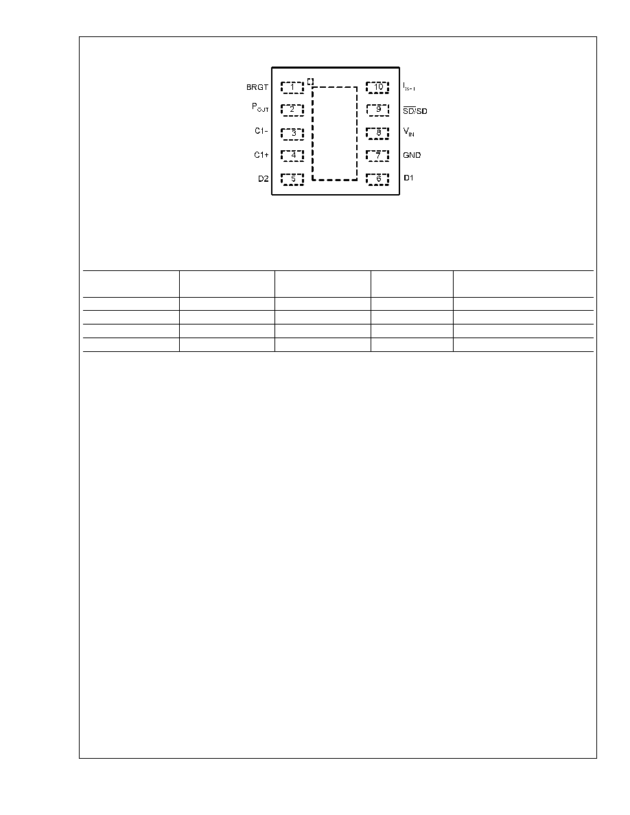
Connection Diagram
20024203
Top View
10-Lead LLP
Ordering Information
Order Number
Shutdown Polarity
NSC Package
Drawing
Package
Marking
Supplied As
LM2792LD-L
Active Low
LLP-10
SRB
1000 Units, Tape and Reel
LM2792LDX-L
Active Low
LLP-10
SRB
4500 Units, Tape and Reel
LM2792LD-H
Active High
LLP-10
SPB
1000 Units, Tape and Reel
LM2792LDX-H
Active High
LLP-10
SPB
4500 Units, Tape and Reel
LM2792
www.national.com
2
Pin Description
Pin
Name
Function
1
BRGT
Variable voltage input controls output current.
2
P
OUT
Charge pump output.
3
C1-
Connect this pin to the negative terminal of C1.
4
C1+
Connect this pin to the positive terminal of C1.
5
D2
Current source outputs. Connect directly to LED.
6
D1
Current source outputs. Connect directly to LED.
7
GND
Power supply ground input.
8
V
IN
Power supply voltage input.
9
SD/SD
Shutdown input. Device operation is inhibited when pin is asserted.
10
I
SET
Current Sense Input. Connect resistor to ground to set constant current through LED.
Block Diagram
20024202
LM2792
www.national.com
3
Absolute Maximum Ratings
(Note 1)
If Military/Aerospace specified devices are required,
please contact the National Semiconductor Sales Office/
Distributors for availability and specifications.
V
IN
-0.3 to 6.0V
BRGT, SD
-0.3 to (V
IN
+0.2V)
Power Dissipation (Note 2)
400 mW
T
JMAX
(Note 2)
150∞C
JA
(Note 7)
55∞C/W
Storge Temperature
-65∞C to +150∞C
Lead Temp. (Soldering, 5 sec.)
260∞C
ESD Rating
Human Body Model
2KV
Machine Model
200V
Operating Conditions
Input Voltage (V
IN
)
3.0V to 5.8V
BRGT
0 to 3.0V
Ambient Temperature (T
A
)
-30∞C to +85∞C
34mAOperating Junction
Temperature
-30∞C to 100∞C
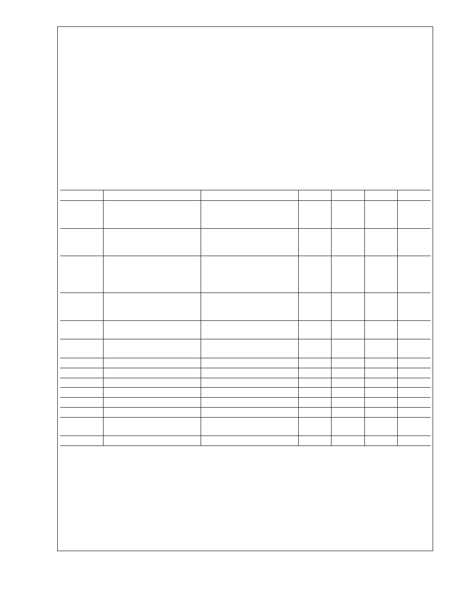
Electrical Characteristics
Limits in standard typeface are for T
J
= 25∞C and limits in boldface type apply over the full Operating Temperature Range.
Unless otherwise specified, C
1
= C
IN
= C
HOLD
= 1 µF, V
IN
= 3.6V, BRGT pin = 2.75V.
Symbol
Parameter
Conditions
Min
Typ
Max
Units
I
DX
Available Current at Output Dx
3.0V
V
IN
5.8V
V
Dx
3.6V
R
SET
= 1650
V
BRGT
= 3V
14.5
16.8
mA
I
DX
Line Regulation of Dx Output
Current
3.0V
V
IN
4.4V
V
Dx
3.6V
R
SET
= 1800
V
BRGT
= 2.75V
13.5
16
17.8
mA
V
DX
Load Regulation of Dx Output
Current
V
IN
= 3.6V
V
Dx
= 3.0V
V
Dx
= 4.0V
R
SET
= 1800
V
BRGT
= 2.75V
16.1
15.4
mA
I
D-MATCH
Current Matching Between Any
Two Outputs
V
D1
= V
D2
= 3.6V,
BRGT = 2.75V, V
IN
= 3.6V,
R
SET
= 1800
0.3
%
I
Q
Quiescent Supply Current
3.0V
V
IN
4.4V, Active, No
Load Current
1.4
2.7
mA
I
SD
Shutdown Supply Current
3.0V
V
IN
5.5V, Shutdown
At 85∞C
0.1
0.3
1
µA
V
IH
SD Input Logic High
3.0V
V
IN
5.5V, Note5
0.8* V
IN
V
V
IL
SD Input Logic Low
3.0V
V
IN
5.5V, Note5
0.2* V
IN
V
I
LEAK-SD
SD Input Leakage Current
0V
V
SD
V
IN
0.01
µA
R
BRGT
BRGT Input Resistance
250
k
BRGT
Brightness Voltage Range
0
3.0
V
I
SET
I
SET
Pin Output Current
I
Dx
/25
mA
f
SW
Switching Frequency (Note 4)
3.0V
V
IN
4.4V
I
D1
= I
D2
16mA
900
1100
1800
kHz
t
START
Startup Time (Note 6)
I
Dx
= 90% steady state
10
µs
Note 1: Absolute maximum ratings indicate limits beyond which damage to the device may occur. Electrical specifications do not apply when operating the device
beyond its rated operating conditions.
Note 2: D1 and D2 may be shorted to GND without damage. P
OUT
may be shorted to GND for 1sec without damage.
Note 3: In the test circuit, all capacitors are 1.0µF, 0.3
maximum ESR capacitors. Capacitors with higher ESR will increase output resistance, reduce output
voltage and efficiency.
Note 4: The output switches operate at one half of the oscillator frequency, f
OSC
= 2f
SW
.
Note 5: The internal thresholds of the Shutdown bar are set at about 40% of V
IN
Note 6: This electrical specification is quarantee by design
Note 7: For more information regarding the LLP package, please refer to National Semiconductor Application note AN1187
LM2792
www.national.com
4
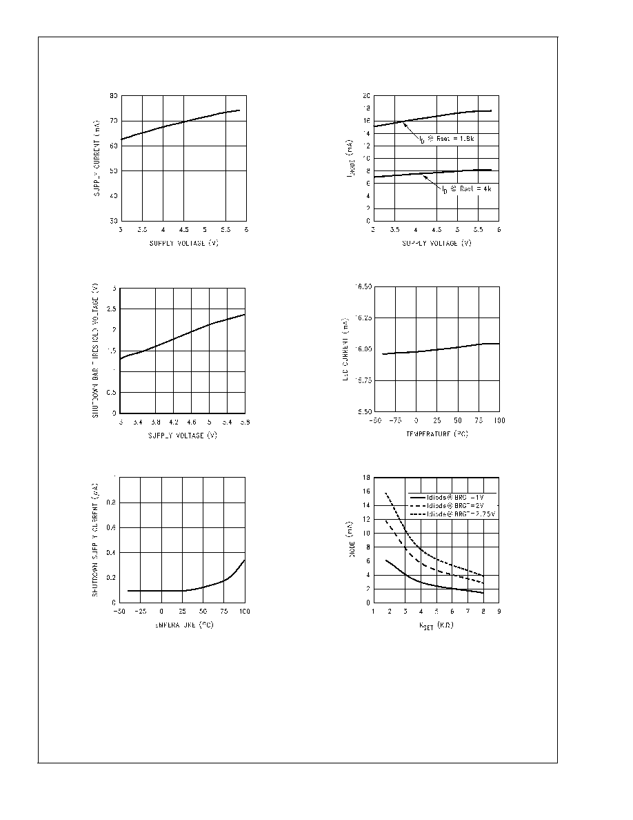
Typical Performance Characteristics
Unless otherwise specified, C
1
= C
IN
= C
HOLD
= 1uF, V
IN
=
3.6V, BRGT pin =2.75V
Input Supply Current vs. V
IN
( I
D1
=I
D2
=16mA)
I
DIODE
vs. V
IN
20024225
20024224
Shutdown Threshold vs. V
IN
I
DIODE
vs. Temperature
20024219
20024207
I
Q(SHUTSOWN)
vs. Temperature
I
DIODE
vs. R
SET
20024210
20024213
LM2792
www.national.com
5