LM384
5W Audio Power Amplifier
General Description
The LM384 is a power audio amplifier for consumer applica-
tion. In order to hold system cost to a minimum, gain is inter-
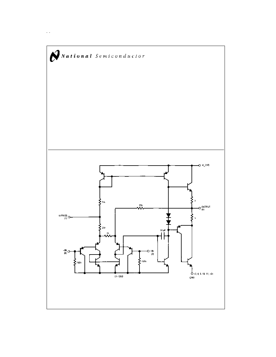
nally fixed at 34 dB. A unique input stage allows inputs to be
ground
referenced.
The
output
is
automatically
self-centering to one half the supply voltage.
The output is short-circuit proof with internal thermal limiting.
The package outline is standard dual-in-line. A copper lead
frame is used with the center three pins on either side com-
prising a heat sink. This makes the device easy to use in
standard p-c layout.
Uses include simple phonograph amplifiers, intercoms, line
drivers, teaching machine outputs, alarms, ultrasonic driv-
ers, TV sound systems, AM-FM radio, sound projector sys-
tems, etc. See AN-69 for circuit details.
Features
n
Wide supply voltage range
n
Low quiescent power drain
n
Voltage gain fixed at 50
n
High peak current capability
n
Input referenced to GND
n
High input impedance
n
Low distortion
n
Quiescent output voltage is at one half of the supply
voltage
n
Standard dual-in-line package
Schematic Diagram
DS007843-3
February 1995
LM384
5W
Audio
Power
Amplifier
� 1999 National Semiconductor Corporation
DS007843
www.national.com
Absolute Maximum Ratings
(Note 1)
If Military/Aerospace specified devices are required,
please contact the National Semiconductor Sales Office/
Distributors for availability and specifications.
Supply Voltage
28V
Peak Current
1.3A
Power Dissipation (See (Notes 4, 5))
1.67W
Input Voltage
�
0.5V
Storage Temperature
-65�C to +150�C
Operating Temperature
0�C to +70�C
Lead Temperature
(Soldering, 10 sec.)
260�C
Thermal Resistance
JC
30�C/W
JA
79�C/W
Note 1: Absolute Maximum Ratings indicate limits beyond which damage to
the device may occur. Operating Ratings indicate conditions for which the de-
vice is functional, but do not guarantee specific performance limits.
Electrical Characteristics
(Note 2)
Symbol
Parameter
Conditions
Min
Typ
Max
Units
Z
IN
Input Resistance
150
k
I
BIAS
Bias Current
Inputs Floating
100
nA
A
V
Gain
40
50
60
V/V
P
OUT
Output Power
THD = 10%, R
L
= 8
5
5.5
W
I
Q
Quiescent Supply Current
8.5
25
mA
V
OUT Q
Quiescent Output Voltage
11
V
BW
Bandwidth
P
OUT
= 2W, R
L
= 8
450
kHz
V
+
Supply Voltage
12
26
V
I
SC
Short Circuit Current (Note 6)
1.3
A
PSRR
RTO
Power Supply Rejection Ratio
31
dB
(Note 3) )
THD
Total Harmonic Distortion
P
OUT
= 4W, R
L
= 8
0.25
1.0
%
Note 2: V
+
= 22V and T
A
= 25�C operating with a Staver V7 heat sink for 30 seconds.
Note 3: Rejection ratio referred to the output with C
BYPASS
= 5 �F, freq = 120 Hz.
Note 4: The maximum junction temperature of the LM384 is 150�C.
Note 5: The package is to be derated at 15�C/W junction to heat sink pins.
Note 6: Output is fully protected against a shorted speaker condition at all voltages up to 22V.
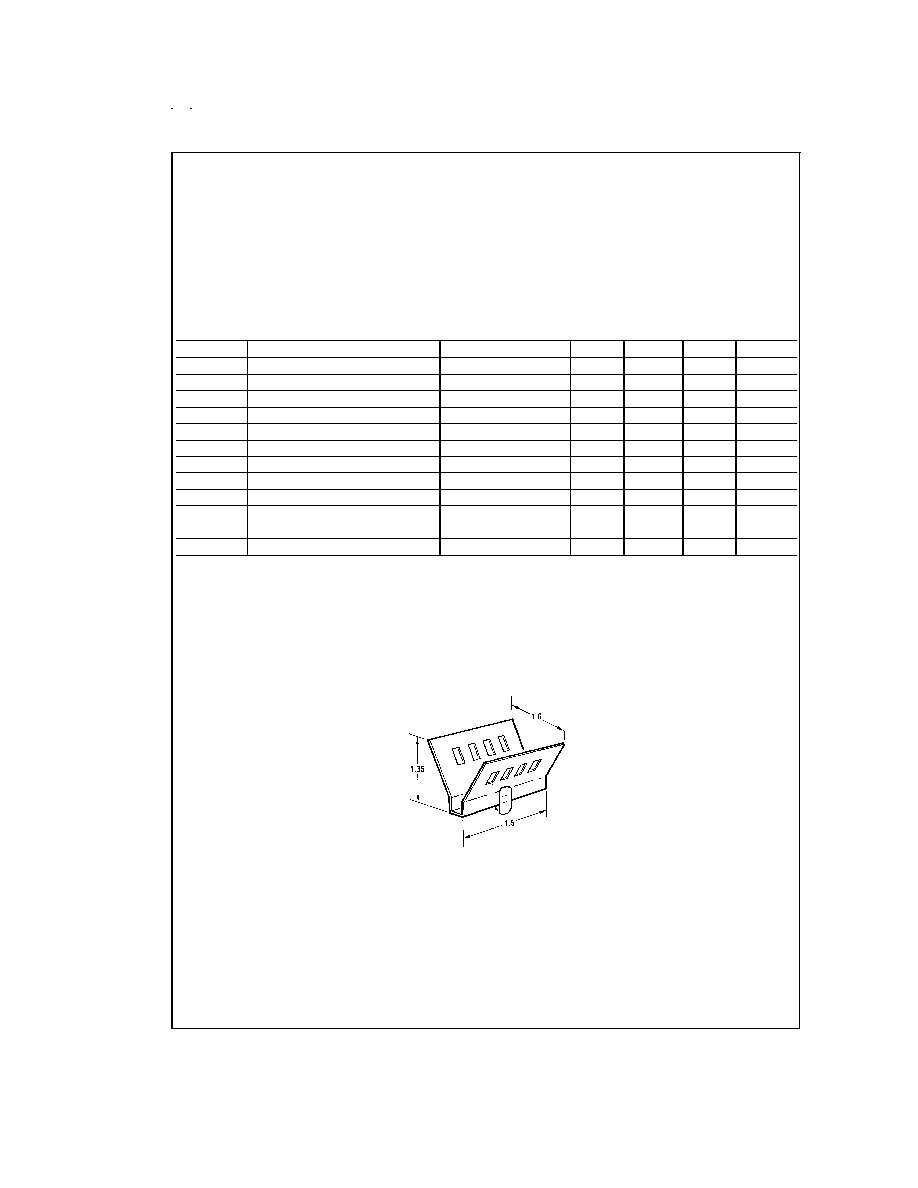
Heat Sink Dimensions
Staver "V7" Heat Sink
DS007843-4
Staver Company
41 Saxon Ave.
P.O. Drawer H
Bay Shore, N.Y.
Tel: (516) 666-8000
www.national.com
2
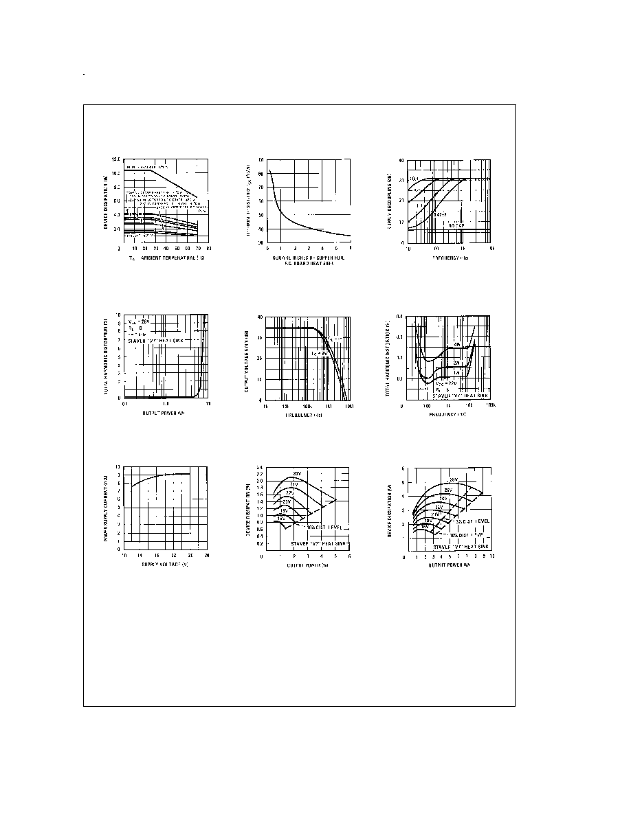
Typical Performance Characteristics
Device Dissipation vs
Ambient Temperature
DS007843-10
Thermal Resistance vs
Square Inches
DS007843-11
Supply Decoupling vs
Frequency
DS007843-12
Total Harmonic Distortion
vs Output Power
DS007843-13
Output Voltage Gain vs
Frequency
DS007843-14
Total Harmonic Distortion
vs Frequency
DS007843-15
Power Supply Current vs
Supply Voltage
DS007843-16
Device Dissipation vs
Output Power -- 16
Load
DS007843-17
Device Dissipation vs
Output Power -- 8
Load
DS007843-18
www.national.com
3
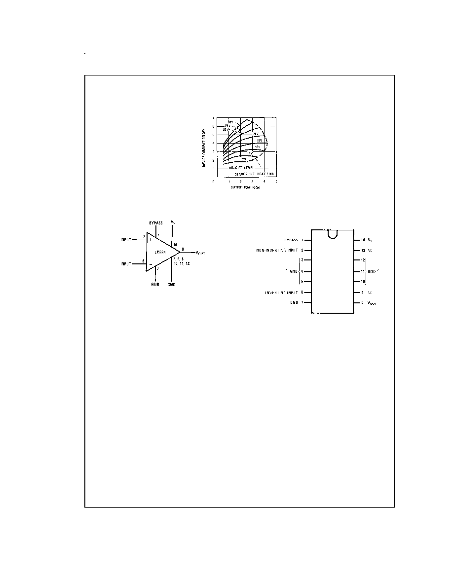
Typical Performance Characteristics
(Continued)
Block and Connection Diagrams
Device Dissipation vs
Output Power -- 4
Load
DS007843-19
DS007843-1
Dual-In-Line Package
DS007843-2
Note 7: Heatsink Pins
Top View
Order Number LM384N
See NS Package Number N14A
www.national.com
4
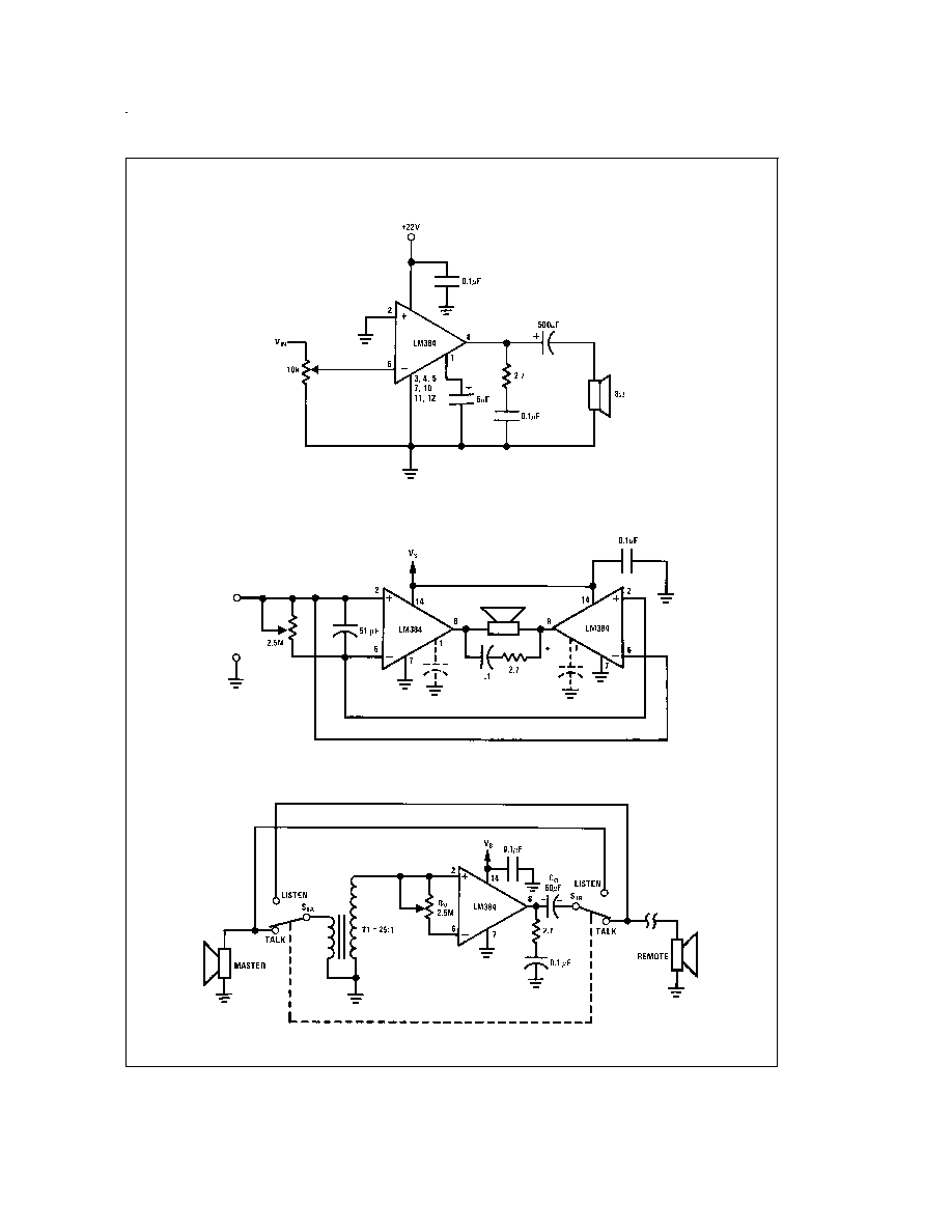
Typical Applications
Typical 5W Amplifier
DS007843-6
Bridge Amplifier
DS007843-7
Intercom
DS007843-8
*For stability with high current loads
www.national.com
5