 | –≠–ª–µ–∫—Ç—Ä–æ–Ω–Ω—ã–π –∫–æ–º–ø–æ–Ω–µ–Ω—Ç: LM3909 | –°–∫–∞—á–∞—Ç—å:  PDF PDF  ZIP ZIP |
TL H 7969
LM3909
LED
FlasherOscillator
February 1995
LM3909 LED Flasher Oscillator
General Description
The LM3909 is a monolithic oscillator specifically designed
to flash Light Emitting Diodes By using the timing capacitor
for voltage boost it delivers pulses of 2 or more volts to the
LED while operating on a supply of 1 5V or less The circuit
is inherently self-starting and requires addition of only a bat-
tery and capacitor to function as an LED flasher
Packaged in an 8-lead plastic mini-DIP the LM3909 will op-
erate over the extended consumer temperature range of
b
25 C to
a
70 C It has been optimized for low power drain
and operation from weak batteries so that continuous oper-
ation life exceeds that expected from battery rating
Application is made simple by inclusion of internal timing
resistors and an internal LED current limit resistor As
shown in the first two application circuits the timing resis-
tors supplied are optimized for nominal flashing rates and
minimum power drain at 1 5V and 3V
Timing capacitors will generally be of the electrolytic type
and a small 3V rated part will be suitable for any LED flasher
using a supply up to 6V However when picking flash rates
it should be remembered that some electrolytics have very
broad capacitance tolerances
for example
b
20% to
a
100%
Features
Y
Operation over one year from one C size flashlight cell
Y
Bright high current LED pulse
Y
Minimum external parts
Y
Low cost
Y
Low voltage operation from just over 1V to 5V
Y
Low current drain averages under 0 5 mA during
battery life
Y
Powerful as an oscillator directly drives an 8X speaker
Y
Wide temperature range
Applications
Y
Finding flashlights in the dark or locating boat mooring
floats
Y
Sales and advertising gimmicks
Y
Emergency locators for instance on fire extinguishers
Y
Toys and novelties
Y
Electronic applications such as trigger and sawtooth
generators
Y
Siren for toy fire engine (combined oscillator speaker
driver)
Y
Warning indicators powered by 1 4V to 200V
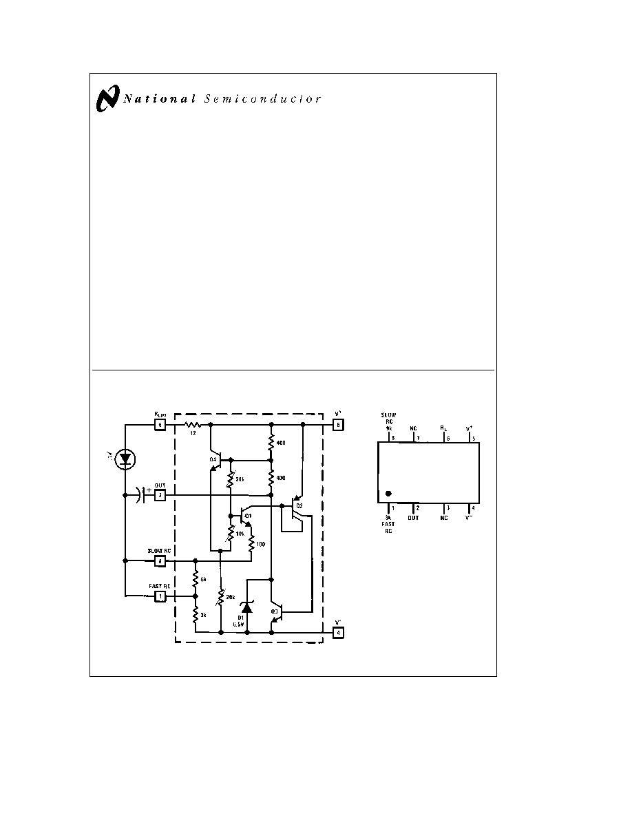
Schematic Diagram
Typical 1 5V Flasher
TL H 7969 ≠ 1
Connection Diagram
Dual-In-Line Package
TL H 7969 ≠ 2
Top View
Order Number LM3909N
See NS Package Number N08E
C1995 National Semiconductor Corporation
RRD-B30M115 Printed in U S A
Absolute Maximum Ratings
If Military Aerospace specified devices are required
please contact the National Semiconductor Sales
Office Distributors for availability and specifications
Power Dissipation
500 mW
V
a
Voltage
6 4V
Operating Temperature Range
b
25 C to
a
70 C
Lead Temperature (Soldering 10 sec )
260 C
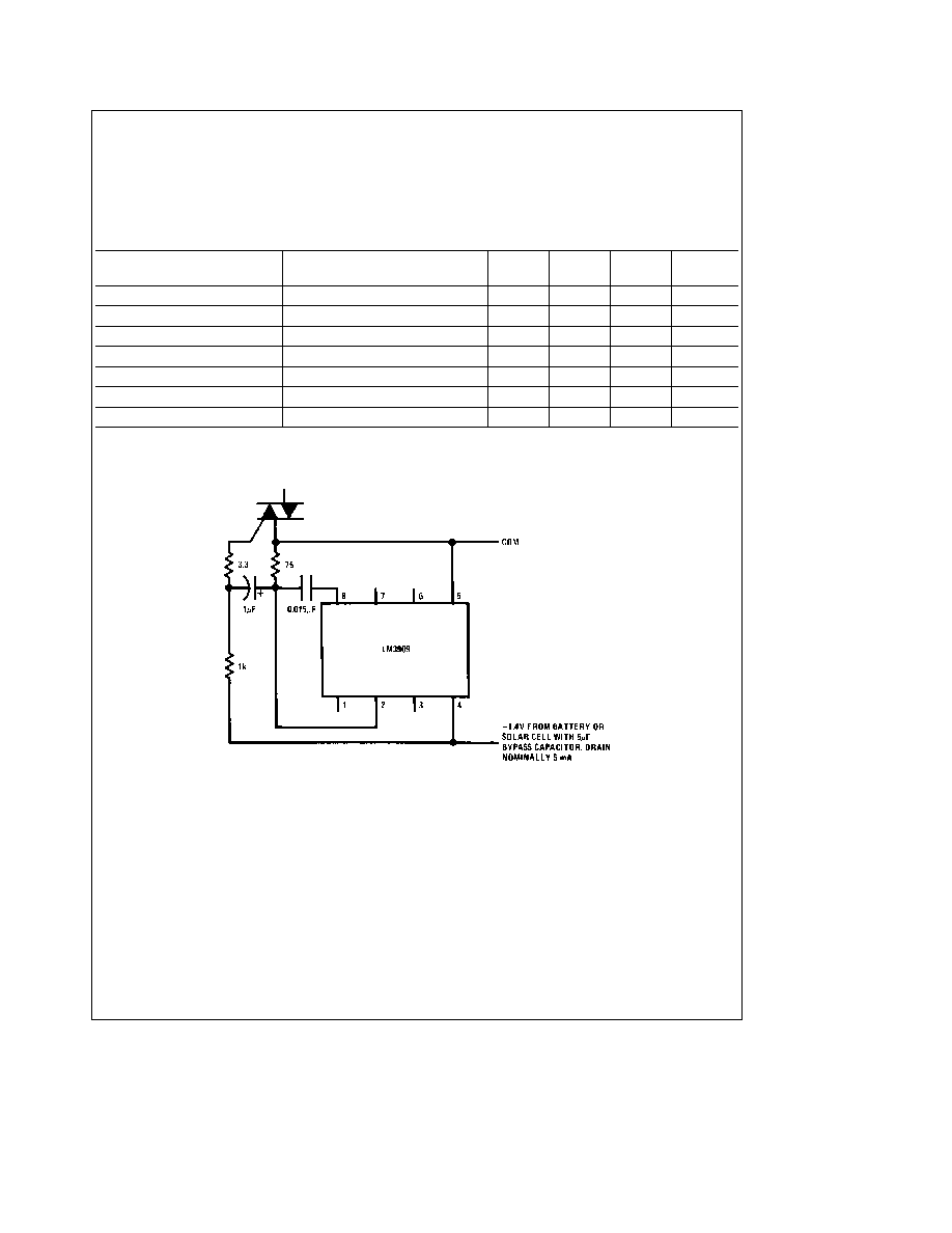
Electrical Characteristics
Parameter
Conditions
Min
Typ
Max
Units
(Applications Note 3)
Supply Voltage
(In Oscillation)
1 15
6 0
V
Operating Current
0 55
0 75
mA
Flash Frequency
300 mF 5% Capacitor
0 65
1 0
1 3
Hz
High Flash Frequency
0 30 mF 5% Capacitor
1 1
kHz
Compatible LED Forward Drop
1 mA Forward Current
1 35
2 1
V
Peak LED Current
350 mF Capacitor
45
mA
Pulse Width
350 mF Capacitors at
Amplitude
6 0
ms
Typical Applications
(See applications notes on following page)
Triac Trigger
Provides 40 mA 10 ms pulses at about 8 kHz
Triac gate may be pulse transformer isolated if
desired
TL H 7969 ≠ 3
2
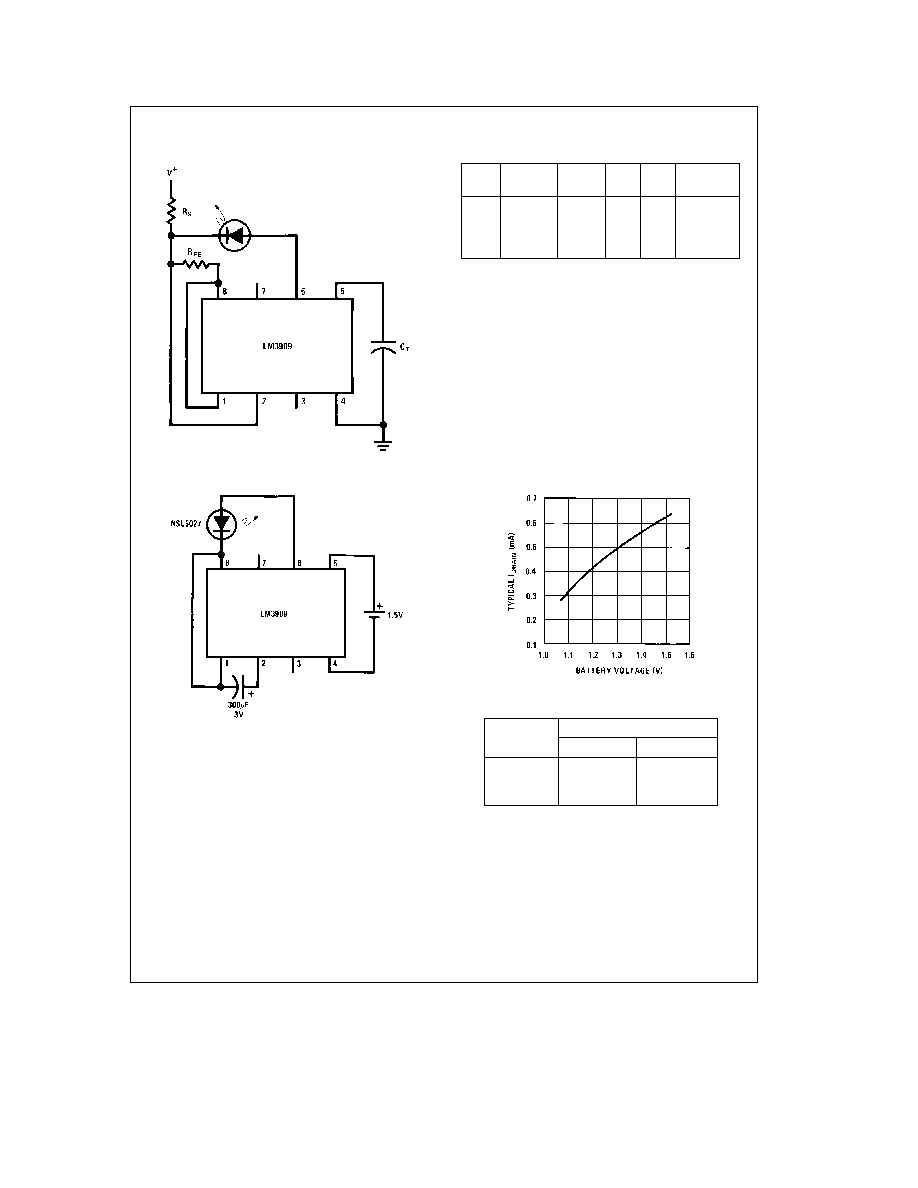
Typical Applications
(Continued)(See applications notes below)
Warning Flasher High Voltage Powered
TL H 7969 ≠ 4
Typical Operating Conditions
V
a
Nominal
C
T
R
S
R
FB
V
a
RANGE
Flash Hz
6V
2
400 mF
1k
1 5k
5V ≠ 25V
15V
2
180 mF
3 9k
1k
13V ≠ 50V
100V
1 7
180 mF
43k
1k
85V ≠ 200V
1W
1 5V Flasher
TL H 7969 ≠ 5
Note
Nominal flash rate 1 Hz
TL H 7969 ≠ 6
Estimated Battery Life
(Continuous 1 5V Flasher Operation)
Size Cell
Type
Standard
Alkaline
AA
3 months
6 months
C
7 months
15 months
D
1 3 years
2 6 years
Note
Estimates are made from our tests and manufacturers
data Conditions are fresh batteries and room temperature Clad
or ``leak-proof'' batteries are recommended for any application
of five months or more Nickel Cadmium cells are not recom-
mended
APPLICATIONS NOTES
Note 1
All capacitors shown are electrolytic unless marked otherwise
Note 2
Flash rates and frequencies assume a
g
5% capacitor tolerance Electrolytics may vary
b
20% to
a
100% of their stated value
Note 3
Unless noted measurements above are made with a 1 4V supply a 25 C ambient temperature and an LED with a forward drop of 1 5V to 1 7V at 1 mA
forward current
Note 4
Occasionally a flasher circuit will fail to oscillate due to an LED defect that may be missed because it only reduces light output 10% or so Such LEDs can
be identified by a large increase in conduction between 0 9V and 1 2V
3
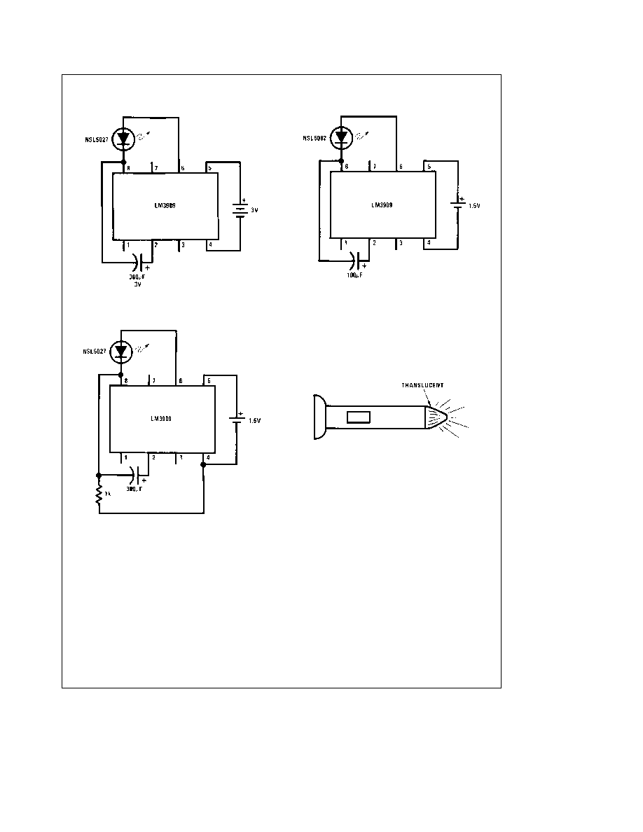
Typical Applications
(Continued) (See applications notes on previous page)
3V Flasher
TL H 7969 ≠ 7
Note
Nominal flash rate 1 Hz Average I
DRAIN
e
0 77 mA
Minimum Power at 1 5V
TL H 7969 ≠ 8
Note
Nominal flash rate 1 1 Hz Average I
DRAIN
e
0 32 mA
Fast Blinker
TL H 7969 ≠ 9
Note
Nominal flash rate 2 6 Hz Average I
DRAIN
e
1 2 mA
TL H 7969 ≠ 11
Note
Winking LED inside locates light in total darkness
4
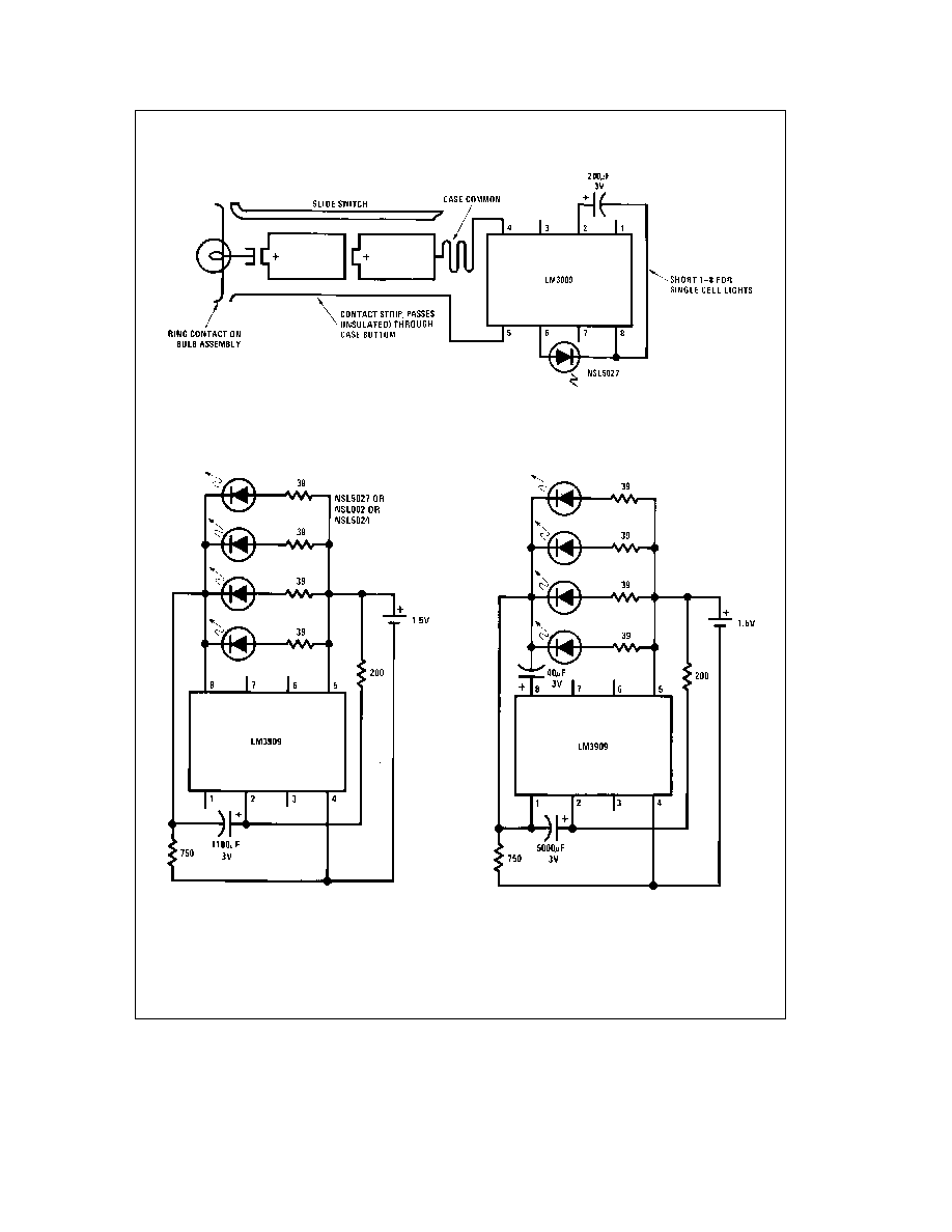
Typical Applications
(Continued) (See applications notes above)
Flashlight Finder
TL H 7969 ≠ 10
Note
LM3909 capacitor and LED are installed in a white translucent cap on the flashlight's back end Only one
contact strip (in addition to the case connection) is needed for flasher power Drawing current through the bulb
simplifies wiring and causes negligible loss since bulb resistance cold is typically less than 2X
4 Parallel LEDs
TL H 7969 ≠ 12
Note
Nominal flash rate 1 3 Hz Average I
DRAIN
e
2 mA
High Efficiency Parallel Circuit
TL H 7969 ≠ 13
Note
Nominal flash rate 1 5 Hz Average I
DRAIN
e
1 5 mA
5