TL H 5701
LM3911
Temperature
Controller
June 1994
LM3911 Temperature Controller
General Description
The LM3911 is a highly accurate temperature measurement
and or control system for use over a
b
25 C to
a
85 C tem-
perature range Fabricated on a single monolithic chip it
includes a temperature sensor a stable voltage reference
and an operational amplifier
The output voltage of the LM3911 is directly proportional to
temperature in degrees Kelvin at 10 mV K Using the inter-
nal op amp with external resistors any temperature scale
factor is easily obtained By connecting the op amp as a
comparator the output will switch as the temperature trans-
verses the set-point making the device useful as an on-off
temperature controller
An active shunt regulator is connected across the power
leads of the LM3911 to provide a stable 6 8V voltage refer-
ence for the sensing system This allows the use of any
power supply voltage with suitable external resistors
The input bias current is low and relatively constant with
temperature ensuring high accuracy when high source im-
pedance is used Further the output collector can be re-
turned to a voltage higher than 6 8V allowing the LM3911 to
drive lamps and relays up to a 35V supply
The LM3911 uses the difference in emitter-base voltage of
transistors operating at different current densities as the ba-
sic temperature sensitive element Since this output de-
pends only on transistor matching the same reliability and
stability as present op amps can be expected
The LM3911 is available in two package styles a metal can
TO-46 and an 8-lead epoxy mini-DIP In the epoxy package
all electrical connections are made on one side of the de-
vice allowing the other 4 leads to be used for attaching the
LM3911 to the temperature souce The LM3911 is rated for
operation over a
b
25 C to
a
85 C temperature range
Features
Y
Uncalibrated accuracy
g
10 C
Y
Internal op amp with frequency compensation
Y
Linear output of 10 mV K (10 mV C)
Y
Can be calibrated in degrees Kelvin Celsius or
Fahrenheit
Y
Output can drive loads up to 35V
Y
Internal stable voltage reference
Y
Low cost
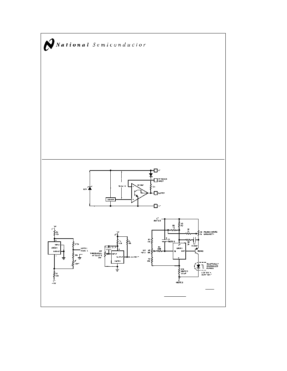
Block Diagram
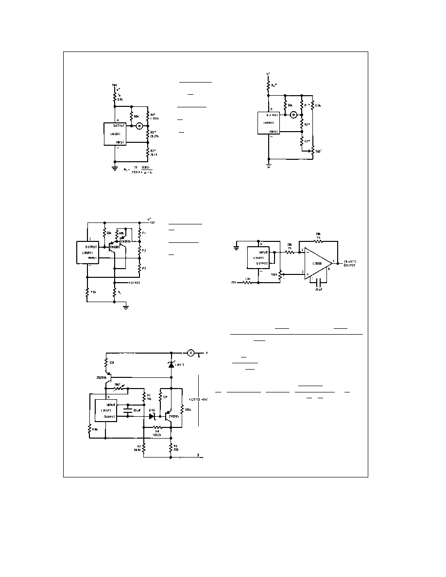
Typical Applications
Ground Referred
Centigrade Thermometer
Trims out initial zener tolerance
Set output to read C
Basic Temperature Controller
Output goes negative on
temperature increase
R
S
e
(V
a
b
6 8V) kX
Proportioning Temperature
Controller
Note 1
C1 determines proportioning frequency f
1
2R4 C1
Note 2
R10
e
l
V
a
l
a
l
V
b
l
b
7V
0 0015A
Note 3
Either V
b
or V
a
can be ground
TL H 5701 ≠ 1
C1995 National Semiconductor Corporation
RRD-B30M115 Printed in U S A
Absolute Maximum Ratings
If Military Aerospace specified devices are required
please contact the National Semiconductor Sales
Office Distributors for availability and specifications
Supply Current (Externally Set)
10 mA
Output Collector Voltage V
a a
36V
Feedback Input Voltage Range
0V to
a
7 0V
Output Short Circuit Duration
Indefinite
Operating Temperature Range
b
25 C to
a
85 C
Storage Temperature Range
b
65 C to
a
150 C
Lead Temperature (Soldering 10 seconds)
260 C
Electrical Characteristics
(Note 1)
Parameter
Conditions
Min
Typ
Max
Units
SENSOR
Output Voltage
T
A
e b
25 C (Note 2)
2 36
2 48
2 60
V
Output Voltage
T
A
e a
25 C (Note 2)
2 88
2 98
3 08
V
Output Voltage
T
A
e a
85 C (Note 2)
3 46
3 58
3 70
V
Linearity
D
T
e
100 C
0 5
2
%
Long-Term Stability
0 3
%
Repeatability
0 3
%
VOLTAGE REFERENCE
Reverse Breakdown Voltage
1 mA
s
I
z
s
5 mA
6 55
6 85
7 25
V
Reverse Breakdown Voltage
1 mA
s
I
z
s
5 mA
10
35
mV
Change With Current
Temperature Stability
20
85
mV
Dynamic Impedance
I
z
e
1 mA
3 0
X
RMS Noise Voltage
10 Hz
s
f
s
10 kHz
30
m
V
Long Term Stability
T
A
e a
85 C
6 0
mV
OP AMP
Input Bias Current
T
A
e a
25 C
35
150
nA
Input Bias Current
45
250
nA
Voltage Gain
R
L
e
36k V
a a
e
36V
2500
15000
V V
Output Leakage Current
T
A
e
25 C (Note 3)
0 2
2
m
A
Output Leakage Current
(Note 3)
1 0
8
m
A
Output Source Current
V
OUT
s
3 70
10
m
A
Output Sink Current
1V
s
V
OUT
s
36V
2 0
mA
Note 1
These specifications apply for
b
25 C
s
T
A
s a
85 C and 0 9 mA
s
I
SUPPLY
s
1 1 mA unless otherwise specified C
L
s
50 pF
Note 2
The output voltage applies to the basic thermometer configuration with the output and input terminals shorted and a load resistance of
t
1 0 MX This is
the feedback sense voltage and includes errors in both the sensor and op amp This voltage is specified for the sensor in a rapidly stirred oil bath The output is
referred to V
a
Note 3
The output leakage current is specified with
t
100 mV overdrive Since this voltage changes with temperature the voltage drive for turn-off changes and is
defined as V
OUT
(with output and input shorted)
b
100 mV This specification applies for V
OUT
e
36V
Application Hints
Although the LM3911 is designed to be totally trouble-free
certain precautions should be taken to insure the best pos-
sible performance
As with any temperature sensor internal power dissipation
will raise the sensor's temperature above ambient Nominal
suggested operating current for the shunt regulator is 1 0
mA and causes 7 0 mW of power dissipation In free still air
this raises the package temperature by about 1 2 K Al-
though the regulator will operate at higher reverse currents
and the output will drive loads up to 5 0 mA these higher
currents will raise the sensor temperature to about 19 K
above ambient-degrading accuracy Therefore the sensor
should be operated at the lowest possible power level
With moving air liquid or surface temperature sensing self-
heating is not as great a problem since the measured
media will conduct the heat from the sensor Also there are
many small heat sinks designed for transistors which will
improve heat transfer to the sensor from the surrounding
medium A small finned clip-on heat sink is quite effective in
free-air It should be mentioned that the LM3911 die is on
the base of the package and therefore coupling to the base
is preferable
The internal reference regulator provides a temperature sta-
ble voltage for offsetting the output or setting a comparison
point in temperature controllers However since this refer-
ence is at the same temperature as the sensor temperature
changes will also cause reference drift For application
where maximum accuracy is needed an external reference
should be used Of course for fixed temperature controllers
the internal reference is adequate
2
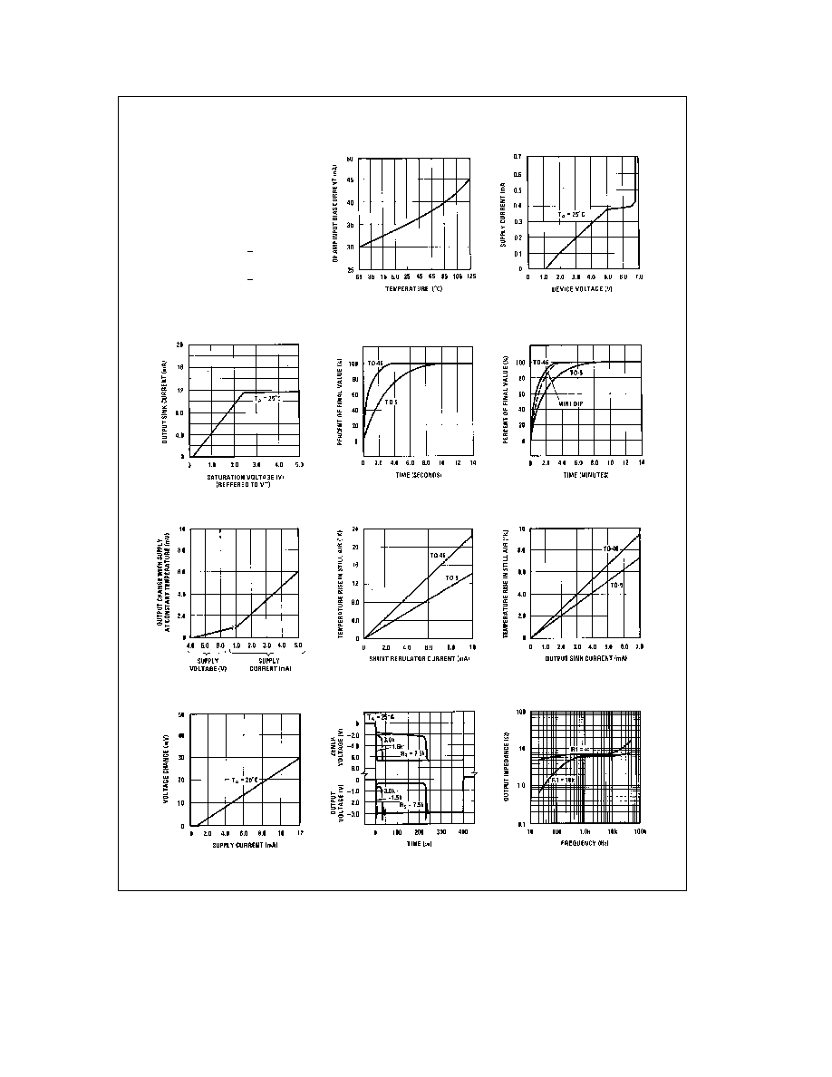
Typical Performance Characteristics
Temperature
Conversion
T
CENTIGRADE
e
T
C
T
FAHRENHEIT
e
T
F
T
KELVIN
e
T
K
T
K
e
T
C
a
273 16
T
C
e
(40
a
T
F
)
5
9
b
40
T
F
e
(40
a
T
C
)
9
5
b
40
Op Amp Input Current
Power Supply Current
Output Saturation
Voltage
Thermal Time Constant
in Stirred Oil Bath
Thermal Time Constant in
Still Air
Supply Sensitivity
Device Temperature Rise
Device Temperature Rise
Reference Regulation
Turn ``ON'' Response
Amplifier Output Impedance
TL H 5701 ≠ 2
3
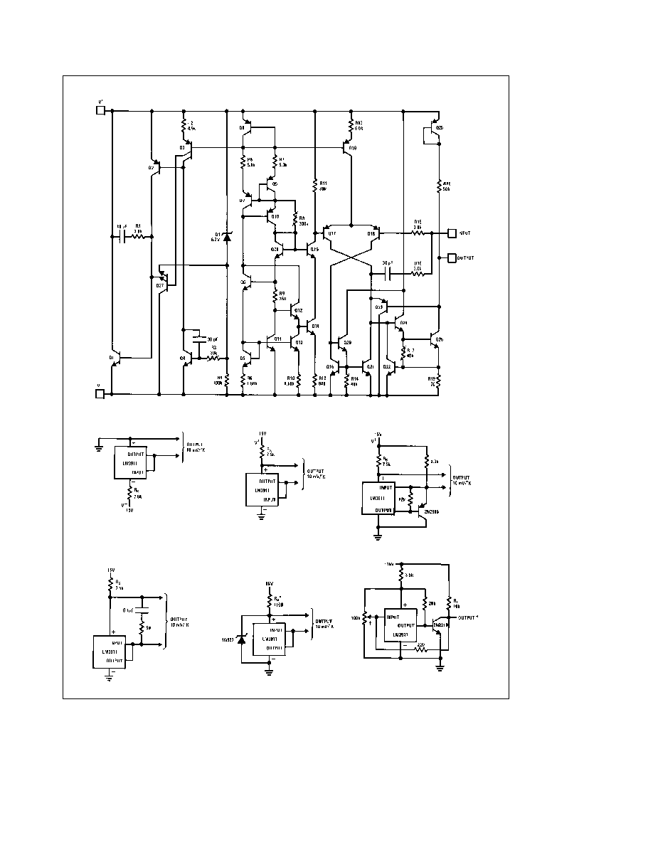
Schematic Diagram
Typical Applications
(Continued)
Basic Thermometer for Negative Supply
Note
Load current to GND
is supplied through R
S
R
S
e
(V
b
b
6 8V)
c
10
3
X
Basic Thermometer
for Positive Supply
R
S
e
(V
b
b
6 8V)
c
10
3
X
Increasing Output Drive
R
S
e
(V
a
b
6 8V)
c
10
3
X
External Frequency Compensation
for Greater Stability when Driving
Capacitive Loads
Operating With External Zener for
Lower Power Dissipation
Depends on Zener current
Temperature Controller With Hysteresis
Output goes positive on temperature increase
Set temperature
TL H 5701 ≠ 3
4
Typical Applications
(Continued)
Thermometer With Meter Output
R1
e
(V
Z
) 0 01DT
I
M
(V
Z
b
0 01 T
O
)
Select I
Q
s
2V
R1
R2
e
0 01 T
O
b
I
Q
R1
I
Q
R3
e
V
Z
I
Q
b
R1
b
R2
I
Q
s
2V
R1
J
V
z
e
Shunt regulator voltage (use 6 85)
D
T
e
Meter temperature span ( K)
I
M
e
Meter full scale current (A)
T
O
e
Meter zero temperature ( K)
I
Q
e
Current through R1 R2 R3 at zero
meter current (10 mA to 1 0 mA) (A)
Values shown for
T
O
e
300 K DT
e
100 K
I
M
e
1 0 mA I
Q
e
100 mA
The 0 01 in the above and following equations is in units of V K or V C
and is a result of the basic 0 01V K sensitivity of the transducer
Ground Referred Thermometer
R1
e
(V
Z
)(10mV)(DT)
V
O
R
L
(V
Z
b
0 01 T
O
)
R2
e
0 01 T
O
b
I
Q
R1
I
Q
R3
e
V
Z
I
Q
b
R1
b
R2
V
z
e
Shunt regulator voltage
D
T
e
Temperature span ( K)
T
O
e
Temperature for zero output ( K)
V
O
e
Full scale output voltage
s
10V
I
Q
e
Current through R1 R2 R3
at zero output voltage
(typically 100 mA to 1 0 mA)
Meter Thermometer With Trimmed Output
Selected as for meter thermometer except T
O
should
be 5 K more than desired and I
Q
e
100 mA
Calibrates T
O
Ground Referred Centigrade Thermometer
Set zero
Two Terminal Temperature to Current Transducer
R2 (X)
e
V
Z
b
0 01 T
L
J
I
H
b
0 01 T
H
R1
J
a
V
Z
b
0 01 T
H
J
0 01 T
L
R1
b
I
L
J
0 01
R1 R3
T
H
(V
Z
b
0 01 T
L
)
b
T
L
(V
Z
b
0 01 T
H
)
(
R3(X)
t
V
Z
T
H
T
L
b
1
J
I
H
b
I
L
T
H
T
L
1
R4
e
1
(V
Z
b
0 01 T
L
)(R2)
%
(R2)(0 01 T
L
)
R1
a
V
Z
b
0 01 T
L
R2
b
I
L
J
1
R2
a
1
R3
≠
b
1
R2
T
L
e
Temperature for I
L
( K)
T
H
e
Temperature for I
H
( K)
V
Z
e
Zener voltage (V)
I
L
e
Low temperature output current (A)
I
H
e
High temperature output current (A)
Values shown for I
OUT
e
1 mA to 10 mA for 10 F to 100 F
Set temperature
TL H 5701 ≠ 4
The 0 01 in the above and following equations is in units of V K or V C and is a result of the basic 0 01V K sensitivity of the transducer
5